Owner Manual
Page 1
...64257;cations 86 Troubleshooting 87 En AV Receiver TX-SR604/604E TX-SR8460 TX-SR674/674E TX-SR8467 Contents Introduction 2 Connections 18 First Time Setup 38 Basic Operations 49 Advanced Operations 66 Instruction Manual Advanced Setup 67 Zone 2 79 Thank... you to obtain optimum performance and listening enjoyment from your new AV Receiver. Please retain this manual will enable you for future reference. Please read this manual thoroughly before making connections and plugging in this manual for purchasing an Onkyo AV Receiver...
...64257;cations 86 Troubleshooting 87 En AV Receiver TX-SR604/604E TX-SR8460 TX-SR674/674E TX-SR8467 Contents Introduction 2 Connections 18 First Time Setup 38 Basic Operations 49 Advanced Operations 66 Instruction Manual Advanced Setup 67 Zone 2 79 Thank... you to obtain optimum performance and listening enjoyment from your new AV Receiver. Please retain this manual will enable you for future reference. Please read this manual thoroughly before making connections and plugging in this manual for purchasing an Onkyo AV Receiver...
Owner Manual
Page 4
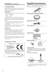
...lead of this adapter if your AC outlet does not match with the plug on the AV receiver's power cord (adapter varies from country to country). *How to the terminal which is &#... for the ASTA mark or the BSI mark on the power supply cord of this instruction manual is marked with the corresponding technical standards such as follows: The wire which is coloured blue... must approved by qualified service personnel. MIYAGI ONKYO EUROPE ELECTRONICS GmbH Front Left Front Left SP-B / Zone 2 Left SP-B / Zone 2 Left Front Right ...
...lead of this adapter if your AC outlet does not match with the plug on the AV receiver's power cord (adapter varies from country to country). *How to the terminal which is &#... for the ASTA mark or the BSI mark on the power supply cord of this instruction manual is marked with the corresponding technical standards such as follows: The wire which is coloured blue... must approved by qualified service personnel. MIYAGI ONKYO EUROPE ELECTRONICS GmbH Front Left Front Left SP-B / Zone 2 Left SP-B / Zone 2 Left Front Right ...
Owner Manual
Page 8
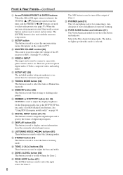
...to MIN, 1 through 99, or MAX. L SETUP MIC (38) The included speaker setup microphone is used to turn off the output of the AV receiver to adjust the volume of Zone 2. See "Using RDS (European models only)" on page 54. Q DISPLAY button (50) This button is used to... button (53) This button is used when storing or deleting radio presets. J MASTER VOLUME control (49) This control is used to select the Auto or Manual tuning mode. M TUNING MODE button (52) This button is used to display various information about the currently selected input source. T TONE, [-] & [+]...
...to MIN, 1 through 99, or MAX. L SETUP MIC (38) The included speaker setup microphone is used to turn off the output of the AV receiver to adjust the volume of Zone 2. See "Using RDS (European models only)" on page 54. Q DISPLAY button (50) This button is used to... button (53) This button is used when storing or deleting radio presets. J MASTER VOLUME control (49) This control is used to select the Auto or Manual tuning mode. M TUNING MODE button (52) This button is used to display various information about the currently selected input source. T TONE, [-] & [+]...
Owner Manual
Page 9
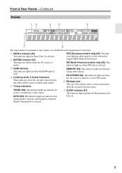
... RDS (European models only) (54): This indicator lights up when the Auto been set. TUNED (52): This indicator lights up when the AV receiver is tuned into a radio station. 7 SLEEP indicator (51) This indicator lights up when the Sleep function has AUTO (52): This indicator lights ...lights up when Zone 2 is selected. 3 HDMI indicator This indicator lights up when presetting radio stations. Tuning mode is selected, and disappears when the Manual Tuning mode is XM (North American models only) (56): This muted. Front & Rear Panels-Continued Display 12 34 5 7 6 The page numbers...
... RDS (European models only) (54): This indicator lights up when the Auto been set. TUNED (52): This indicator lights up when the AV receiver is tuned into a radio station. 7 SLEEP indicator (51) This indicator lights up when the Sleep function has AUTO (52): This indicator lights ...lights up when Zone 2 is selected. 3 HDMI indicator This indicator lights up when presetting radio stations. Tuning mode is selected, and disappears when the Manual Tuning mode is XM (North American models only) (56): This muted. Front & Rear Panels-Continued Display 12 34 5 7 6 The page numbers...

Owner Manual
Page 13
...: see page 85 Note: Some of the remote controller operations described in this manual may not work as expected with each type of the REMOTE MODE buttons to control the AV receiver. ENT DIMMER SLEEP TV VOL INPUT GUIDE TOP MENU CH DISC ALBUM VOL PREVIOUS...used to control the compo- nent. I TV, VCR and SAT/CABLE Modes With these modes, you can control RECEIVER the AV receiver and an Onkyo cassette TAPE recorder connected via . 1 2 3 4 1 5 2 36 7 4 8 9 J ON/STANDBY ZONE2 REMOTE MODE RECEIVER TAPE INPUT SELECTOR 1 2 3 V1 V2 V3 DVD M D/CDR CD HDD 4 5 6 TV V4 MULTI CH...
...: see page 85 Note: Some of the remote controller operations described in this manual may not work as expected with each type of the REMOTE MODE buttons to control the AV receiver. ENT DIMMER SLEEP TV VOL INPUT GUIDE TOP MENU CH DISC ALBUM VOL PREVIOUS...used to control the compo- nent. I TV, VCR and SAT/CABLE Modes With these modes, you can control RECEIVER the AV receiver and an Onkyo cassette TAPE recorder connected via . 1 2 3 4 1 5 2 36 7 4 8 9 J ON/STANDBY ZONE2 REMOTE MODE RECEIVER TAPE INPUT SELECTOR 1 2 3 V1 V2 V3 DVD M D/CDR CD HDD 4 5 6 TV V4 MULTI CH...
Owner Manual
Page 18
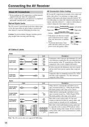
... typically used to connect composite video inputs and outputs. The audio quality is commonly used instead of a multichannel cable. Note: The AV receiver does not support SCART plugs. 18 It's the most L common connection format for analog audio, and R can be found on TVs,... standard analog audio cables can be used on virtually all AV connections. Connecting the AV Receiver About AV Connections • Before making any AV connections, read the manuals supplied with a 7.1-channel analog audio output. AV Cables & Jacks AV Connection Color Coding RCA-type AV connections ...
... typically used to connect composite video inputs and outputs. The audio quality is commonly used instead of a multichannel cable. Note: The AV receiver does not support SCART plugs. 18 It's the most L common connection format for analog audio, and R can be found on TVs,... standard analog audio cables can be used on virtually all AV connections. Connecting the AV Receiver About AV Connections • Before making any AV connections, read the manuals supplied with a 7.1-channel analog audio output. AV Cables & Jacks AV Connection Color Coding RCA-type AV connections ...
Owner Manual
Page 28
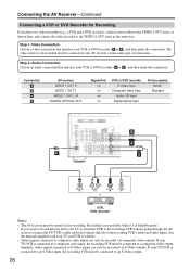
...input Picture quality Better Standard CB BA b a OPTICAL IN L R AUDIO IN S VIDEO IN VIDEO IN VCR, DVD recorder Notes: • The AV receiver must be connected to a composite video output. Step 1: Video Connection Choose a video connection that matches your TV/VCR is not possible while it's in ... recording VCR must be connected to the recording VCR's audio and video inputs. See the manuals supplied with your TV or playback VCR to the recording VCR without going through the AV receiver, connect the TV/VCR's audio and video outputs directly to an S-Video output. 28 If...
...input Picture quality Better Standard CB BA b a OPTICAL IN L R AUDIO IN S VIDEO IN VIDEO IN VCR, DVD recorder Notes: • The AV receiver must be connected to a composite video output. Step 1: Video Connection Choose a video connection that matches your TV/VCR is not possible while it's in ... recording VCR must be connected to the recording VCR's audio and video inputs. See the manuals supplied with your TV or playback VCR to the recording VCR without going through the AV receiver, connect the TV/VCR's audio and video outputs directly to an S-Video output. 28 If...
Owner Manual
Page 34
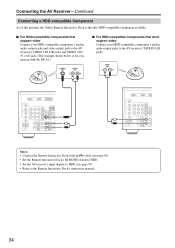
... support video Connect your HDD-compatible component's analog audio output jacks and video output jack to the AV receiver's VIDEO 3 IN L/R jacks and VIDEO 3 IN (V or S) jack. (The example shown below...audio output jacks to the AV receiver's TAPE IN L/R jacks. Connecting the AV Receiver-Continued Connecting a HDD-compatible Component As of this printing, the Onkyo Remote Interactive Dock is for connection... with an cable (see page 36). • Set the Remote Interactive Dock's RI MODE switch to HDD. • Set the AV receiver's input...
... support video Connect your HDD-compatible component's analog audio output jacks and video output jack to the AV receiver's VIDEO 3 IN L/R jacks and VIDEO 3 IN (V or S) jack. (The example shown below...audio output jacks to the AV receiver's TAPE IN L/R jacks. Connecting the AV Receiver-Continued Connecting a HDD-compatible Component As of this printing, the Onkyo Remote Interactive Dock is for connection... with an cable (see page 36). • Set the Remote Interactive Dock's RI MODE switch to HDD. • Set the AV receiver's input...
Owner Manual
Page 36
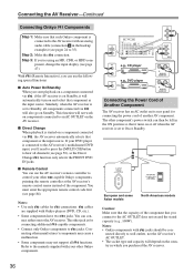
...page 47). nect either one to wall outlets, not the AV receiver's AC OUTLET. • The socket type and capacity will automatically turn on Standby. I Remote Control You can use the AV receiver's remote controller to the manuals supplied with an analog audio cable (connection a in the ON ... the power cord of Another Component The AV receiver has an AC outlet on or off when the AV receiver is set to hear all channels (see pages 24 to 35). Connecting the AV Receiver-Continued Connecting Onkyo Components Step 1: Make sure that each Onkyo component is connected to the AV...
...page 47). nect either one to wall outlets, not the AV receiver's AC OUTLET. • The socket type and capacity will automatically turn on Standby. I Remote Control You can use the AV receiver's remote controller to the manuals supplied with an analog audio cable (connection a in the ON ... the power cord of Another Component The AV receiver has an AC outlet on or off when the AV receiver is set to hear all channels (see pages 24 to 35). Connecting the AV Receiver-Continued Connecting Onkyo Components Step 1: Make sure that each Onkyo component is connected to the AV...
Owner Manual
Page 52
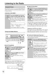
...TUNED indicator appears. D TUN 2 (Actual display depends on country) Tuning into AM and FM stations directly by entering the appropriate frequency. 1 RECEIVER Press the [RECEIVER] button, followed by the [D TUN] button. TUNED AUTO FM STEREO 52 Listening to the Radio Using the Tuner With the built-in mono... one step at a time. Listening to the Radio TUNER Use the [TUNER] input selector button to change FM frequency in mono. I Manual Tuning Mode 1 TUNING MODE Press the [TUNING MODE] button so that the AUTO indicator appears on the display. 2 TUNING PRESET Press the...
...TUNED indicator appears. D TUN 2 (Actual display depends on country) Tuning into AM and FM stations directly by entering the appropriate frequency. 1 RECEIVER Press the [RECEIVER] button, followed by the [D TUN] button. TUNED AUTO FM STEREO 52 Listening to the Radio Using the Tuner With the built-in mono... one step at a time. Listening to the Radio TUNER Use the [TUNER] input selector button to change FM frequency in mono. I Manual Tuning Mode 1 TUNING MODE Press the [TUNING MODE] button so that the AUTO indicator appears on the display. 2 TUNING PRESET Press the...

Owner Manual
Page 65
...) connected to the to the VIDEO 1 OUT jacks. VIDEO 1 VIDEO 2 VCR1 VCR2 You can be output. VIDEO 3 VIDEO 4 TAPE ing. The AV receiver's VOLUME con- AV Recording Audio sources can watch the source while record- ing. 3 On the source component, start playback on the VCR and start playback...such as the video source. 5 Start recording on the camcorder and CD player. Recording Separate AV Sources Here you want DVD to the manuals supplied with recording capability, and how to digital recording. This selects the CD player as the audio source, but leaves the camcorder as...
...) connected to the to the VIDEO 1 OUT jacks. VIDEO 1 VIDEO 2 VCR1 VCR2 You can be output. VIDEO 3 VIDEO 4 TAPE ing. The AV receiver's VOLUME con- AV Recording Audio sources can watch the source while record- ing. 3 On the source component, start playback on the VCR and start playback...such as the video source. 5 Start recording on the camcorder and CD player. Recording Separate AV Sources Here you want DVD to the manuals supplied with recording capability, and how to digital recording. This selects the CD player as the audio source, but leaves the camcorder as...
Owner Manual
Page 67
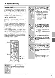
...select "b. Here you change one of the connected speakers after using the Automatic Speaker Setup function. quency will be selected here. 1 RECEIVER Press the [RECEIVER] button followed by the Automatic Speaker Setup function (see page 38). Speaker Config," and then press [ENTER]. Use the ...Speaker Setup function (see page 38). Note: If the Front setting in step 4 is set them manually, which speakers are set to determine 4 the optimum crossover frequencies. 1 2 ON/STANDBY ZONE2 REMOTE MODE RECEIVER TAPE INPUT SELECTOR 1 2 3 V1 V2 V3 DVD M D/CDR C D HDD 4 5 ...
...select "b. Here you change one of the connected speakers after using the Automatic Speaker Setup function. quency will be selected here. 1 RECEIVER Press the [RECEIVER] button followed by the Automatic Speaker Setup function (see page 38). Speaker Config," and then press [ENTER]. Use the ...Speaker Setup function (see page 38). Note: If the Front setting in step 4 is set them manually, which speakers are set to determine 4 the optimum crossover frequencies. 1 2 ON/STANDBY ZONE2 REMOTE MODE RECEIVER TAPE INPUT SELECTOR 1 2 3 V1 V2 V3 DVD M D/CDR C D HDD 4 5 ...
Owner Manual
Page 71
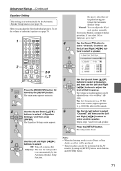
... and Right [ ]/[ ] buttons to select another speaker. Press the [SETUP] button. SETUP 2 Use the Up and Down [ ]/[ ] buttons to select "Channel," and then use the Left and Right [ ]/[ ] but- Be sure to Direct or Pure Audio, no effect will be produced. • This procedure can...Up [ ] button to select "4. Advanced Setup-Continued Equalizer Setting This setting is set the volume of individual speakers. Manual: You can be performed on the AV receiver by the Automatic Speaker Setup function. To set automatically by the [SETUP] button. ENT DIMMER SLEEP TV VOL INPUT GUIDE...
... and Right [ ]/[ ] buttons to select another speaker. Press the [SETUP] button. SETUP 2 Use the Up and Down [ ]/[ ] buttons to select "Channel," and then use the Left and Right [ ]/[ ] but- Be sure to Direct or Pure Audio, no effect will be produced. • This procedure can...Up [ ] button to select "4. Advanced Setup-Continued Equalizer Setting This setting is set the volume of individual speakers. Manual: You can be performed on the AV receiver by the Automatic Speaker Setup function. To set automatically by the [SETUP] button. ENT DIMMER SLEEP TV VOL INPUT GUIDE...

Owner Manual
Page 77
...is detected automatically. With this preference, you have set the signal format to select: PCM, DTS, or Auto. Digital signals in that you can manually set , flashes, and only signals in other formats are locked, you can protect your settings by the [SETUP] button. The main menu... setting the format to select "9. However, if you experience either of tracks from a PCM source are output. DIGITAL INPUT 1 Press and hold the AV receiver's [DIGITAL INPUT] button for the input sources that format are cut off, try setting the format to PCM. • If noise is displayed (about ...
...is detected automatically. With this preference, you have set the signal format to select: PCM, DTS, or Auto. Digital signals in that you can manually set , flashes, and only signals in other formats are locked, you can protect your settings by the [SETUP] button. The main menu... setting the format to select "9. However, if you experience either of tracks from a PCM source are output. DIGITAL INPUT 1 Press and hold the AV receiver's [DIGITAL INPUT] button for the input sources that format are cut off, try setting the format to PCM. • If noise is displayed (about ...


