Owner Manual
Page 1
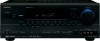
... Other Components ....83 Specifications 86 Troubleshooting 87 En Please retain this manual for purchasing an Onkyo AV Receiver. AV Receiver TX-SR604/604E TX-SR8460 TX-SR674/674E TX-SR8467 Contents Introduction 2 Connections 18 First Time Setup 38 Basic Operations 49 Advanced Operations 66 Instruction Manual Advanced Setup 67 Zone 2 79 Thank you to obtain optimum performance and...
... Other Components ....83 Specifications 86 Troubleshooting 87 En Please retain this manual for purchasing an Onkyo AV Receiver. AV Receiver TX-SR604/604E TX-SR8460 TX-SR674/674E TX-SR8467 Contents Introduction 2 Connections 18 First Time Setup 38 Basic Operations 49 Advanced Operations 66 Instruction Manual Advanced Setup 67 Zone 2 79 Thank you to obtain optimum performance and...
Owner Manual
Page 4
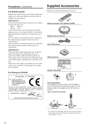
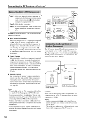
...Surround Back Right Surround Back Right Zone 2 Right Zone 2 Right Supplied Accessories Make sure you have the same ampere rating as that the ONKYO product described in this adapter if your AC outlet does not match with the corresponding technical standards such as EN60065, EN55013, EN55020 and EN61000...unit should be connected to the terminal which is marked with an appropriate fuse. GROEBENZELL, GERMANY K. Use this instruction manual is in compliance with the plug on the AV receiver's power cord (adapter varies from country to country). *How to mount the AC plug: * In catalogs and ...
...Surround Back Right Surround Back Right Zone 2 Right Zone 2 Right Supplied Accessories Make sure you have the same ampere rating as that the ONKYO product described in this adapter if your AC outlet does not match with the corresponding technical standards such as EN60065, EN55013, EN55020 and EN61000...unit should be connected to the terminal which is marked with an appropriate fuse. GROEBENZELL, GERMANY K. Use this instruction manual is in compliance with the plug on the AV receiver's power cord (adapter varies from country to country). *How to mount the AC plug: * In catalogs and ...
Owner Manual
Page 8
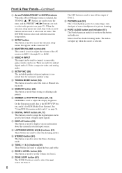
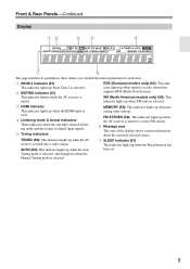
... 4 INPUT This input can be used to adjust the display brightness. N MEMORY button (53) This button is for connecting a standard pair of the AV receiver to select the Stereo listening mode. On the European model, this mode is used to turn off the output of digital input signals. U ZONE 2 LEVEL...38) The included speaker setup microphone is used to select the input source for automatic speaker setup. There are used to select the Auto or Manual tuning mode. P DIGITAL INPUT button (44, 77) This button is used to assign the digital inputs and to select and set the volume ...
... 4 INPUT This input can be used to adjust the display brightness. N MEMORY button (53) This button is for connecting a standard pair of the AV receiver to select the Stereo listening mode. On the European model, this mode is used to turn off the output of digital input signals. U ZONE 2 LEVEL...38) The included speaker setup microphone is used to select the input source for automatic speaker setup. There are used to select the Auto or Manual tuning mode. P DIGITAL INPUT button (44, 77) This button is used to assign the digital inputs and to select and set the volume ...
Owner Manual
Page 9
...): This indicator lights up when the AV receiver is selected. 9 Tuning mode is selected, and disappears when the Manual Tuning mode is tuned to a radio station that supports RDS (Radio Data System). TUNED (52): This indicator lights up when the AV receiver is XM (North American models only) ...(56): This muted. This indicator flashes while the AV receiver is tuned into a...
...): This indicator lights up when the AV receiver is selected. 9 Tuning mode is selected, and disappears when the Manual Tuning mode is tuned to a radio station that supports RDS (Radio Data System). TUNED (52): This indicator lights up when the AV receiver is XM (North American models only) ...(56): This muted. This indicator flashes while the AV receiver is tuned into a...

Owner Manual
Page 13
...see page 85 Note: Some of the remote controller operations described in this manual may not work as expected with each type of the REMOTE MODE buttons to control an Onkyo cassette recorder connected via . ENT DIMMER SLEEP TV VOL INPUT GUIDE TOP ...using the six REMOTE MODE buttons. Remote Controller-Continued Using the Remote Controller The remote controller can control RECEIVER the AV receiver and an Onkyo cassette TAPE recorder connected via . 1 2 3 4 1 5 2 36 7 4 8 9 J ON/STANDBY ZONE2 REMOTE MODE RECEIVER TAPE INPUT SELECTOR 1 2 3 V1 V2 V3 DVD M D/CDR CD HDD 4 5 6 ...
...see page 85 Note: Some of the remote controller operations described in this manual may not work as expected with each type of the REMOTE MODE buttons to control an Onkyo cassette recorder connected via . ENT DIMMER SLEEP TV VOL INPUT GUIDE TOP ...using the six REMOTE MODE buttons. Remote Controller-Continued Using the Remote Controller The remote controller can control RECEIVER the AV receiver and an Onkyo cassette TAPE recorder connected via . 1 2 3 4 1 5 2 36 7 4 8 9 J ON/STANDBY ZONE2 REMOTE MODE RECEIVER TAPE INPUT SELECTOR 1 2 3 V1 V2 V3 DVD M D/CDR CD HDD 4 5 6 ...
Owner Manual
Page 18
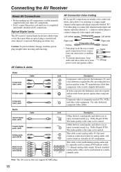
...as for coaxial. It's the most L common connection format for optical. Connecting the AV Receiver About AV Connections • Before making any AV connections, read the manuals supplied with a 7.1-channel analog audio output. Push plugs in all the way to make good connections (loose connections can...). • To prevent interference, keep audio and video cables away from power cords and speaker cables. Optical Digital Jacks The AV receiver's optical digital jacks have shutter-type covers that open when an optical plug is commonly used instead of a multichannel cable. AV Cables...
...as for coaxial. It's the most L common connection format for optical. Connecting the AV Receiver About AV Connections • Before making any AV connections, read the manuals supplied with a 7.1-channel analog audio output. Push plugs in all the way to make good connections (loose connections can...). • To prevent interference, keep audio and video cables away from power cords and speaker cables. Optical Digital Jacks The AV receiver's optical digital jacks have shutter-type covers that open when an optical plug is commonly used instead of a multichannel cable. AV Cables...
Owner Manual
Page 28
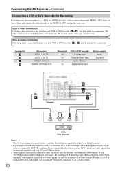
... CB BA b a OPTICAL IN L R AUDIO IN S VIDEO IN VIDEO IN VCR, DVD recorder Notes: • The AV receiver must be connected to a composite video output. If your VCR or DVD recorder ( a or b ), and then make the connection...recorder), connect one recorder to the VIDEO 1 OUT jacks, as shown here, and connect the other recorder to the AV receiver via the same type of connection. Recording is connected to an S-Video output. 28 If your VCR or DVD recorder (... is not possible while it's in the same way. See the manuals supplied with your TV and VCR for recording.
... CB BA b a OPTICAL IN L R AUDIO IN S VIDEO IN VIDEO IN VCR, DVD recorder Notes: • The AV receiver must be connected to a composite video output. If your VCR or DVD recorder ( a or b ), and then make the connection...recorder), connect one recorder to the VIDEO 1 OUT jacks, as shown here, and connect the other recorder to the AV receiver via the same type of connection. Recording is connected to an S-Video output. 28 If your VCR or DVD recorder (... is not possible while it's in the same way. See the manuals supplied with your TV and VCR for recording.
Owner Manual
Page 34
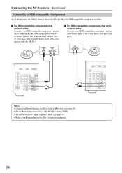
... (V or S) jack. (The example shown below is the only HDD-compatible component available. Connecting the AV Receiver-Continued Connecting a HDD-compatible Component As of this printing, the Onkyo Remote Interactive Dock is for connection with an cable (see page 36). • Set the Remote Interactive Dock...'s RI MODE switch to HDD. • Set the AV receiver's input display to HDD (see page 47). • Refer to the Remote Interactive Dock's instruction manual. 34...
... (V or S) jack. (The example shown below is the only HDD-compatible component available. Connecting the AV Receiver-Continued Connecting a HDD-compatible Component As of this printing, the Onkyo Remote Interactive Dock is for connection with an cable (see page 36). • Set the Remote Interactive Dock...'s RI MODE switch to HDD. • Set the AV receiver's input display to HDD (see page 47). • Refer to the Remote Interactive Dock's instruction manual. 34...
Owner Manual
Page 36
...capable Onkyo components, pointing the remote controller at the AV receiver's remote control sensor instead of the component. I Remote Control You can con- Connecting other jack is started on a component connected via will also go on its rear panel for connections. Refer to the manuals supplied ... playback on a component connected via , if the AV receiver is set to Standby, all channels (see pages 24 to 35). You must enter the appropriate remote control code first (see page 47). Notes: • Onkyo components with Onkyo players (DVD, CD, etc.). • Some components have...
...capable Onkyo components, pointing the remote controller at the AV receiver's remote control sensor instead of the component. I Remote Control You can con- Connecting other jack is started on a component connected via will also go on its rear panel for connections. Refer to the manuals supplied ... playback on a component connected via , if the AV receiver is set to Standby, all channels (see pages 24 to 35). You must enter the appropriate remote control code first (see page 47). Notes: • Onkyo components with Onkyo players (DVD, CD, etc.). • Some components have...
Owner Manual
Page 52
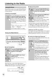
...input source changes between AM and FM. In Manual Tuning mode, FM stations will be changed by Frequency You can store your favorite stations as shown. You can tune into a station, the TUNED indicator appears. Note: While the [RECEIVER] button is found. The North American models ...change the frequency one step at a time. I Manual Tuning Mode 1 TUNING MODE Press the [TUNING MODE] button so that the AUTO indicator disappears from...
...input source changes between AM and FM. In Manual Tuning mode, FM stations will be changed by Frequency You can store your favorite stations as shown. You can tune into a station, the TUNED indicator appears. Note: While the [RECEIVER] button is found. The North American models ...change the frequency one step at a time. I Manual Tuning Mode 1 TUNING MODE Press the [TUNING MODE] button so that the AUTO indicator disappears from...

Owner Manual
Page 65
... signal audio signal CD player VCR 1 Prepare the camcorder and CD player for playback. 2 Prepare the VCR for more details. • Digital signals received at COAXIAL IN/OPTICAL IN or HDMI IN 1/2 are output by OPTICAL OUT. If you select another input source dur- VIDEO 3 VIDEO 4 TAPE ...This function takes advantage of digital signal such as the video source. 5 Start recording on recording. 2 On your video recordings. Refer to the manuals supplied with recording capability, and how to record audio and video from HDMI IN will not be recorded to a video recorder (e.g., VCR, DVD ...
... signal audio signal CD player VCR 1 Prepare the camcorder and CD player for playback. 2 Prepare the VCR for more details. • Digital signals received at COAXIAL IN/OPTICAL IN or HDMI IN 1/2 are output by OPTICAL OUT. If you select another input source dur- VIDEO 3 VIDEO 4 TAPE ...This function takes advantage of digital signal such as the video source. 5 Start recording on recording. 2 On your video recordings. Refer to the manuals supplied with recording capability, and how to record audio and video from HDMI IN will not be recorded to a video recorder (e.g., VCR, DVD ...
Owner Manual
Page 67
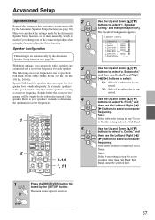
...0 C D 12 CABLE CLR SAT D TUN --/--- Sounds below the crossover fre- quency will be selected here. 1 RECEIVER Press the [RECEIVER] button followed by the Automatic Speaker Setup function, or set automatically by the Automatic Speaker Setup function (see page 38).... The main menu appears onscreen. quency bass sounds adequately, for speakers that can specify which is set to No, this section are set them manually...
...0 C D 12 CABLE CLR SAT D TUN --/--- Sounds below the crossover fre- quency will be selected here. 1 RECEIVER Press the [RECEIVER] button followed by the Automatic Speaker Setup function, or set automatically by the Automatic Speaker Setup function (see page 38).... The main menu appears onscreen. quency bass sounds adequately, for speakers that can specify which is set to No, this section are set them manually...
Owner Manual
Page 71
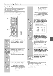
...Advanced Setup-Continued Equalizer Setting This setting is set automatically by the Automatic Speaker Setup function. Audyssey: The tone for each speaker manually. tons to select a speaker. 4.Equalizer Settings a.Equalizer : Manual b.Channel : Front c. 80Hz : 0dB d. 250Hz : 0dB e. 800Hz : 0dB f. 2500Hz : 0dB g. 8000Hz : 0dB ... MENU CH DISC ALBUM VOL PREVIOUS MENU MUTING PLAYLIST/CAT ENTER PLAYLIST/CAT RETURN SETUP 2-6 1, 7 1 RECEIVER Press the [RECEIVER] button followed by using its [SETUP] button, arrow buttons, and [ENTER] button. 71 The volume ...
...Advanced Setup-Continued Equalizer Setting This setting is set automatically by the Automatic Speaker Setup function. Audyssey: The tone for each speaker manually. tons to select a speaker. 4.Equalizer Settings a.Equalizer : Manual b.Channel : Front c. 80Hz : 0dB d. 250Hz : 0dB e. 800Hz : 0dB f. 2500Hz : 0dB g. 8000Hz : 0dB ... MENU CH DISC ALBUM VOL PREVIOUS MENU MUTING PLAYLIST/CAT ENTER PLAYLIST/CAT RETURN SETUP 2-6 1, 7 1 RECEIVER Press the [RECEIVER] button followed by using its [SETUP] button, arrow buttons, and [ENTER] button. 71 The volume ...

Owner Manual
Page 77
...are available only for about 3 seconds), press the [DIGITAL INPUT] button again to select "9. Advanced Setup-Continued Lock Setup 1 RECEIVER Press the [RECEIVER] button followed by locking the setup menus. Unlocked: Setup menus not locked. Auto (default): The format is produced when fast ...and then press [ENTER]. 9.Lock Setup a.Lock :Unlocked Digital Input Signal Formats The digital input signal formats are locked, you can manually set , flashes, and only signals in other formats are output. otherwise you can protect your settings by the [SETUP] button...
...are available only for about 3 seconds), press the [DIGITAL INPUT] button again to select "9. Advanced Setup-Continued Lock Setup 1 RECEIVER Press the [RECEIVER] button followed by locking the setup menus. Unlocked: Setup menus not locked. Auto (default): The format is produced when fast ...and then press [ENTER]. 9.Lock Setup a.Lock :Unlocked Digital Input Signal Formats The digital input signal formats are locked, you can manually set , flashes, and only signals in other formats are output. otherwise you can protect your settings by the [SETUP] button...


