Owner Manual
Page 1
... before making connections and plugging in this manual for purchasing an Onkyo AV Receiver. Enjoying the Listening Modes ..... 48 Advanced Operation 54 Troubleshooting 62 En Please retain this manual will enable you for future reference. Following the instructions in the unit. AV Receiver TX-SR504 TX-SR504E TX-SR8450 Instruction Manual Contents Introduction 2 Connection 16 Turning On & First Time Setup...
... before making connections and plugging in this manual for purchasing an Onkyo AV Receiver. Enjoying the Listening Modes ..... 48 Advanced Operation 54 Troubleshooting 62 En Please retain this manual will enable you for future reference. Following the instructions in the unit. AV Receiver TX-SR504 TX-SR504E TX-SR8450 Instruction Manual Contents Introduction 2 Connection 16 Turning On & First Time Setup...

Owner Manual
Page 4
If the power cord's plug is in compliance with the corresponding technical standards such as that the ONKYO product described in this instruction manual is not suitable for the ASTA mark or the BSI mark on packaging, the letter at the end of the product name ...indicates the color. For European Models Declaration of Conformity We, ONKYO EUROPE ELECTRONICS GmbH LIEGNITZERSTRASSE 6, 82194 GROEBENZELL, GERMANY declare in your AC outlet does not match with the plug on the AV receiver's power cord. (Adapter varies from country to country.) 1 2 3 Speaker Cable Speaker...
If the power cord's plug is in compliance with the corresponding technical standards such as that the ONKYO product described in this instruction manual is not suitable for the ASTA mark or the BSI mark on packaging, the letter at the end of the product name ...indicates the color. For European Models Declaration of Conformity We, ONKYO EUROPE ELECTRONICS GmbH LIEGNITZERSTRASSE 6, 82194 GROEBENZELL, GERMANY declare in your AC outlet does not match with the plug on the AV receiver's power cord. (Adapter varies from country to country.) 1 2 3 Speaker Cable Speaker...
Owner Manual
Page 9
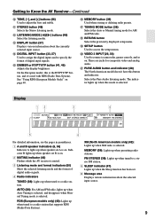
...(North American models only) (42): Lights up when tuned to a radio station. R RETURN button Selects the previously displayed setup menu. Getting to Know the AV Receiver-Continued J TONE, [-], and [+] buttons (46) Used to access the setup menus. N DIGITAL INPUT button (33, 57) Used to assign the digital inputs ... MEMORY (39): Lights up when tuned to a stereo FM station. 5 SLEEP indicator (47) Lights up when Auto Tuning is selected, and disappears when Manual Tuning mode is the RT/PTY/TP button, and it's used with RDS (Radio Data System). FM STEREO (38): Lights up when tuned to a ...
...(North American models only) (42): Lights up when tuned to a radio station. R RETURN button Selects the previously displayed setup menu. Getting to Know the AV Receiver-Continued J TONE, [-], and [+] buttons (46) Used to access the setup menus. N DIGITAL INPUT button (33, 57) Used to assign the digital inputs ... MEMORY (39): Lights up when tuned to a stereo FM station. 5 SLEEP indicator (47) Lights up when Auto Tuning is selected, and disappears when Manual Tuning mode is the RT/PTY/TP button, and it's used with RDS (Radio Data System). FM STEREO (38): Lights up when tuned to a ...
Owner Manual
Page 12
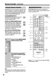
...has a specific operating mode for use with each type of the remote controller operations described in this manual may not work as expected with other manufacturers (see page 59). You must enter the appropriate remote control code... Q Buttons 1, 2, 3, and 4 are selected by using the six REMOTE MODE buttons. ■ RECEIVER/TAPE Mode In RECEIVER/TAPE mode, you can control RECEIVER the AV receiver and an Onkyo cassette TAPE recorder connected via . 1 2 3 1 4 2 5 36 7 4 8 9 J ON/STANDBY REMOTE MODE RECEIVER DVD TAPE INPUT SELECTOR 1 2 3 V1 V2 V3 M D/CDR C D HDD 4 5 6...
...has a specific operating mode for use with each type of the remote controller operations described in this manual may not work as expected with other manufacturers (see page 59). You must enter the appropriate remote control code... Q Buttons 1, 2, 3, and 4 are selected by using the six REMOTE MODE buttons. ■ RECEIVER/TAPE Mode In RECEIVER/TAPE mode, you can control RECEIVER the AV receiver and an Onkyo cassette TAPE recorder connected via . 1 2 3 1 4 2 5 36 7 4 8 9 J ON/STANDBY REMOTE MODE RECEIVER DVD TAPE INPUT SELECTOR 1 2 3 V1 V2 V3 M D/CDR C D HDD 4 5 6...

Owner Manual
Page 20
Connecting Your Components About AV Connections • Before making any AV connections, read the manuals supplied with a 7.1channel analog audio output. AV Cables and Jacks AV Connection Color Coding RCA-type AV connections are usually color coded: red, white, ... The audio quality is inserted and close when it's removed. Use red plugs to connect right-channel audio inputs and outputs (typically labeled "R"). Push plugs in all AV connections. Optical Digital Jacks The AV receiver's optical digital jacks have shutter-type covers that open when an optical plug is the same as...
Connecting Your Components About AV Connections • Before making any AV connections, read the manuals supplied with a 7.1channel analog audio output. AV Cables and Jacks AV Connection Color Coding RCA-type AV connections are usually color coded: red, white, ... The audio quality is inserted and close when it's removed. Use red plugs to connect right-channel audio inputs and outputs (typically labeled "R"). Push plugs in all AV connections. Optical Digital Jacks The AV receiver's optical digital jacks have shutter-type covers that open when an optical plug is the same as...

Owner Manual
Page 29
...switch to HDD. • Set the AV receiver's Input Display to HDD (see page 33). • Refer to the AV receiver's TAPE IN L/R jacks. Connecting Your Components-Continued Connecting an HDD-compatible Component As of this printing, the Onkyo Remote Interactive Dock is the only HDD-compatible ... analog audio output jacks and S-Video output jack to the AV receiver's VIDEO 2 IN L/R jacks and VIDEO 2 IN S jack. ■ For HDD-compatible components that don't support video Connect your HDD-compatible component's analog audio output jacks to the Remote Interactive Dock's instruction manual. 29
...switch to HDD. • Set the AV receiver's Input Display to HDD (see page 33). • Refer to the AV receiver's TAPE IN L/R jacks. Connecting Your Components-Continued Connecting an HDD-compatible Component As of this printing, the Onkyo Remote Interactive Dock is the only HDD-compatible ... analog audio output jacks and S-Video output jack to the AV receiver's VIDEO 2 IN L/R jacks and VIDEO 2 IN S jack. ■ For HDD-compatible components that don't support video Connect your HDD-compatible component's analog audio output jacks to the Remote Interactive Dock's instruction manual. 29
Owner Manual
Page 31
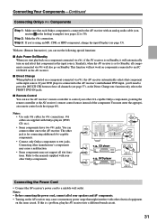
... the Power Cord • Connect the AV receiver's power cord to the AV receiver. Step 2: Make the connection. Notes: • Use only cables for connecting additional -capable components. • Connect only Onkyo components to Standby, all channels (see page 37), as the input source....When playback is started on components connected to the manuals supplied with your other Onkyo components. Connecting Your Components-Continued Connecting Onkyo Components Step 1: Make sure that each Onkyo component is connected to the AV receiver with an analog audio cable (connection a in the...
... the Power Cord • Connect the AV receiver's power cord to the AV receiver. Step 2: Make the connection. Notes: • Use only cables for connecting additional -capable components. • Connect only Onkyo components to Standby, all channels (see page 37), as the input source....When playback is started on components connected to the manuals supplied with your other Onkyo components. Connecting Your Components-Continued Connecting Onkyo Components Step 1: Make sure that each Onkyo component is connected to the AV receiver with an analog audio cable (connection a in the...
Owner Manual
Page 33
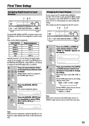
... output digital audio. If, for example, you connect your DVD player to the AV receiver digitally (coaxial or optical). Changing the Input Display If you connect an -capable Onkyo MiniDisc recorder, CD recorder or next generation HDD-compatible component to the TAPE IN/OUT ...digital inputs assign. The current assignment appears. 3 DIGITAL INPUT Press the [DIGITAL INPUT] button repeatedly to the relevant manuals. 33 Note: Make sure that you can only be changed on the AV receiver. 1, 2 1, 2 STANDBY/ON STANDBY PHONES TUNING PRESET MULTI CH DVD VIDEO 1 VIDEO 2 VIDEO 3 TAPE ...
... output digital audio. If, for example, you connect your DVD player to the AV receiver digitally (coaxial or optical). Changing the Input Display If you connect an -capable Onkyo MiniDisc recorder, CD recorder or next generation HDD-compatible component to the TAPE IN/OUT ...digital inputs assign. The current assignment appears. 3 DIGITAL INPUT Press the [DIGITAL INPUT] button repeatedly to the relevant manuals. 33 Note: Make sure that you can only be changed on the AV receiver. 1, 2 1, 2 STANDBY/ON STANDBY PHONES TUNING PRESET MULTI CH DVD VIDEO 1 VIDEO 2 VIDEO 3 TAPE ...

Owner Manual
Page 38
... the radio. 38 TUNED AUTO FM STEREO Tuning into a stereo FM station, the FM STEREO indicator also appears. In this case, switch to Manual Tuning mode and listen to get good reception. Band Frequency (Actual display depends on the display. 2 TUNING PRESET Press the TUNING Up or Down...Auto Tuning Mode 1 TUNING MODE Press the [TUNING MODE] button so that the AUTO indicator disappears from a stereo FM station is found. ■ Manual Tuning Mode 1 TUNING MODE Press the [TUNING MODE] button so that the AUTO indicator appears on country.) ■ AM Frequency Step Setup (not...
... the radio. 38 TUNED AUTO FM STEREO Tuning into a stereo FM station, the FM STEREO indicator also appears. In this case, switch to Manual Tuning mode and listen to get good reception. Band Frequency (Actual display depends on the display. 2 TUNING PRESET Press the TUNING Up or Down...Auto Tuning Mode 1 TUNING MODE Press the [TUNING MODE] button so that the AUTO indicator disappears from a stereo FM station is found. ■ Manual Tuning Mode 1 TUNING MODE Press the [TUNING MODE] button so that the AUTO indicator appears on country.) ■ AM Frequency Step Setup (not...

Owner Manual
Page 53
... setting determines how Dolby Digital EX signals are connected or speaker set B is located centrally. Manual: You can select 0 dB (default), +5 dB, +10 dB, or +15 dB. Input Channel Settings ■ Multiplex This setting determines which channel is output when the Mono listening mode is output. The default value is output from a stereo...
... setting determines how Dolby Digital EX signals are connected or speaker set B is located centrally. Manual: You can select 0 dB (default), +5 dB, +10 dB, or +15 dB. Input Channel Settings ■ Multiplex This setting determines which channel is output when the Mono listening mode is output. The default value is output from a stereo...

Owner Manual
Page 55
...step 4). 4 Use the Down [ ] button to the subwoofer. To get the best bass performance from your speakers. 1 RECEIVER Press the [RECEIVER] REMOTE MODE button, followed by feeding bass sounds from the front left and right channels is being used. SP Config," and then press [ENTER]. 3 Use the Down [ ] button to select "Crossover...]/[ ] buttons to select a crossover fre- Advanced Setup Advanced Speaker Settings The Crossover Frequency, Double Bass, and Speaker Distance settings cannot be set if in the manuals supplied with step 4 of the "Double Bass" setting below.
...step 4). 4 Use the Down [ ] button to the subwoofer. To get the best bass performance from your speakers. 1 RECEIVER Press the [RECEIVER] REMOTE MODE button, followed by feeding bass sounds from the front left and right channels is being used. SP Config," and then press [ENTER]. 3 Use the Down [ ] button to select "Crossover...]/[ ] buttons to select a crossover fre- Advanced Setup Advanced Speaker Settings The Crossover Frequency, Double Bass, and Speaker Distance settings cannot be set if in the manuals supplied with step 4 of the "Double Bass" setting below.

