Owner Manual
Page 1
Following the instructions in the unit. Please read this manual for purchasing an Onkyo AV Receiver. Please retain this manual thoroughly before making connections and plugging in this manual will enable you for future reference. Contents Introduction 2 Connection 18 Turning On & ... Setup .....42 Basic Operations 60 Using the Listening Modes ........74 Advanced Setup 84 NET 107 Multi Zone 115 Controlling Other Components....123 Others 138 En AV Receiver TX-NR807 HT-RC180 Instruction Manual Thank you to obtain optimum performance and listening enjoyment from your new...
Following the instructions in the unit. Please read this manual for purchasing an Onkyo AV Receiver. Please retain this manual thoroughly before making connections and plugging in this manual will enable you for future reference. Contents Introduction 2 Connection 18 Turning On & ... Setup .....42 Basic Operations 60 Using the Listening Modes ........74 Advanced Setup 84 NET 107 Multi Zone 115 Controlling Other Components....123 Others 138 En AV Receiver TX-NR807 HT-RC180 Instruction Manual Thank you to obtain optimum performance and listening enjoyment from your new...

Owner Manual
Page 3
... packaging to Part 15 of the following measures: • Reorient or relocate the receiving antenna. • Increase the separation between the equipment and receiver. • Connect the equipment into an outlet on this unit or its power cord while your Onkyo dealer. 8. Don't use the unit for help. For U.S. Make sure that interference...
... packaging to Part 15 of the following measures: • Reorient or relocate the receiving antenna. • Increase the separation between the equipment and receiver. • Connect the equipment into an outlet on this unit or its power cord while your Onkyo dealer. 8. Don't use the unit for help. For U.S. Make sure that interference...
Owner Manual
Page 4
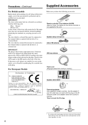
... the coloured markings identifying the terminals in compliance with the corresponding technical standards such as EN60065, EN55013, EN55020 and EN61000-3-2, -3-3. MIYAGI ONKYO EUROPE ELECTRONICS GmbH 1 Speaker Cable 2 FRONT LEFT FRONT LEFT FRONT RIGHT FRONT RIGHT SURROUND LEFT SURROUND LEFT SURROUND RIGHT SURROUND RIGHT CENTER... blue must be connected to the terminal which is not supplied for the remote controller is marked with the plug on the AV receiver's power cord (adapter varies from country to mount the AC plug: FRONT HIGH RIGHT FRONT HIGH RIGHT FRONT HIGH RIGHT FRONT...
... the coloured markings identifying the terminals in compliance with the corresponding technical standards such as EN60065, EN55013, EN55020 and EN61000-3-2, -3-3. MIYAGI ONKYO EUROPE ELECTRONICS GmbH 1 Speaker Cable 2 FRONT LEFT FRONT LEFT FRONT RIGHT FRONT RIGHT SURROUND LEFT SURROUND LEFT SURROUND RIGHT SURROUND RIGHT CENTER... blue must be connected to the terminal which is not supplied for the remote controller is marked with the plug on the AV receiver's power cord (adapter varies from country to mount the AC plug: FRONT HIGH RIGHT FRONT HIGH RIGHT FRONT HIGH RIGHT FRONT...
Owner Manual
Page 5
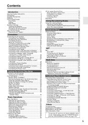
...a Dock with the Universal Port Connector....... 40 Connecting Onkyo V Components 41 Connecting the Power Cord 41 Turning On & First Time Setup Turning On the AV receiver 42 Turning On and Standby 42 First Time Setup 43 Monitor Setup (TX-NR807 43 Selecting the Language used for the onscreen setup ... Signal Formats 103 Using the Audio Settings 104 NET NET 107 About NET 107 Connecting the AV Receiver 107 Listening to Internet Radio 108 Playing Music Files on a Server 109 Network Settings 113 Multi Zone Multi Zone 115 Multiroom Capability 115 Connecting Zone 2 116 Connecting Zone ...
...a Dock with the Universal Port Connector....... 40 Connecting Onkyo V Components 41 Connecting the Power Cord 41 Turning On & First Time Setup Turning On the AV receiver 42 Turning On and Standby 42 First Time Setup 43 Monitor Setup (TX-NR807 43 Selecting the Language used for the onscreen setup ... Signal Formats 103 Using the Audio Settings 104 NET NET 107 About NET 107 Connecting the AV Receiver 107 Listening to Internet Radio 108 Playing Music Files on a Server 109 Network Settings 113 Multi Zone Multi Zone 115 Multiroom Capability 115 Connecting Zone 2 116 Connecting Zone ...
Owner Manual
Page 6
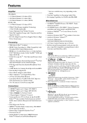
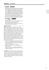
...Network Capability for Streaming Audio Files • Bi-Amping Capability for FL/FR with SBL/SBR Miscellaneous • 40 SIRIUS*8/AM/FM Presets (TX-NR807: North American models) • 40 AM/FM Presets (TX-NR807... double-D symbol are proprietary trademarks of Dolby Laboratories. *4. To receive HD Radio broadcasts, you must install an Onkyo UP-HT1 HD Radio tuner module (sold separately). *7. New ...DSP Connections • 6 HDMI*5 Inputs and 1 Output (TX-NR807) • 5 HDMI*5 Inputs and 1 Output (HT-RC180) • Onkyo for System Control • 6 Digital Inputs (3 Optical/3 Coaxial...
...Network Capability for Streaming Audio Files • Bi-Amping Capability for FL/FR with SBL/SBR Miscellaneous • 40 SIRIUS*8/AM/FM Presets (TX-NR807: North American models) • 40 AM/FM Presets (TX-NR807... double-D symbol are proprietary trademarks of Dolby Laboratories. *4. To receive HD Radio broadcasts, you must install an Onkyo UP-HT1 HD Radio tuner module (sold separately). *7. New ...DSP Connections • 6 HDMI*5 Inputs and 1 Output (TX-NR807) • 5 HDMI*5 Inputs and 1 Output (HT-RC180) • Onkyo for System Control • 6 Digital Inputs (3 Optical/3 Coaxial...
Owner Manual
Page 7
... in the U.S. THX Select2 Plus requirements define hundreds of Apple Inc., registered in Alaska and Hawaii. *9. THX Select2 Plus receivers also feature proprietary THX technologies (e.g., THX Mode) which is your guarantee that is protected by Macrovision Corporation, and is intended ..."x.v.Color" is a registered trademark of Niles Audio Corporation. * Apple and iPod are the property of the Digital Living Network Alliance." (TX-NR807) This product incorporates copyright protection technology that the Home Theater products you purchase will give you superb performance for both digital ...
... in the U.S. THX Select2 Plus requirements define hundreds of Apple Inc., registered in Alaska and Hawaii. *9. THX Select2 Plus receivers also feature proprietary THX technologies (e.g., THX Mode) which is your guarantee that is protected by Macrovision Corporation, and is intended ..."x.v.Color" is a registered trademark of Niles Audio Corporation. * Apple and iPod are the property of the Digital Living Network Alliance." (TX-NR807) This product incorporates copyright protection technology that the Home Theater products you purchase will give you superb performance for both digital ...
Owner Manual
Page 8
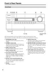
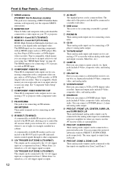
... to open the flap The actual front panel has various logos printed on it flashes while a signal is being received from the remote controller. See "Volume Setup" on page 10. The transmitter transmits setting data to the remote ... The indicator lights up when Zone 3 is used to set the AV receiver to On or Standby. D ZONE 2 indicator (120) This indicator lights up when the AV receiver is in parentheses show where you can also be displayed as an...I DISPLAY button (61) This button is used to adjust the volume of the AV receiver to -2 dB, -81.5 dB through +18.0 dB (relative display).
... to open the flap The actual front panel has various logos printed on it flashes while a signal is being received from the remote controller. See "Volume Setup" on page 10. The transmitter transmits setting data to the remote ... The indicator lights up when Zone 3 is used to set the AV receiver to On or Standby. D ZONE 2 indicator (120) This indicator lights up when the AV receiver is in parentheses show where you can also be displayed as an...I DISPLAY button (61) This button is used to adjust the volume of the AV receiver to -2 dB, -81.5 dB through +18.0 dB (relative display).

Owner Manual
Page 10
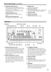
... back left SB: Surround back SBR: Surround back right C ZONE 2 indicator (120) Lights up when the AV receiver can be set to ON to set to On or Standby. L M NO F NETWORK indicator (108) Lights up when Powered Zone 2 is being used to connect a camcorder, game console, and ... for composite video, analog audio, and optical digital audio. Y AUX INPUT (36) This input can establish a connection to OFF, the AV receiver is set the AV receiver to "Bi-Amp". The following abbreviations indicate which audio channels are jacks for Zone 2 or Zone 3. [ MUSIC OPTIMIZER button (105) Turns...
... back left SB: Surround back SBR: Surround back right C ZONE 2 indicator (120) Lights up when the AV receiver can be set to ON to set to On or Standby. L M NO F NETWORK indicator (108) Lights up when Powered Zone 2 is being used to connect a camcorder, game console, and ... for composite video, analog audio, and optical digital audio. Y AUX INPUT (36) This input can establish a connection to OFF, the AV receiver is set the AV receiver to "Bi-Amp". The following abbreviations indicate which audio channels are jacks for Zone 2 or Zone 3. [ MUSIC OPTIMIZER button (105) Turns...
Owner Manual
Page 11
...Input Setup" on page 50. E RS232 (TX-NR807) Terminal for connecting the AV receiver to "Audyssey" or Audyssey Dynamic Surround Expansion™... Rear Panel (TX-NR807) * North American models B C DEFG H* IJ KL M NO P Q R ST U VW X Y Z[ " B DIGITAL OPTICAL IN 1 and 2 These optical digital audio inputs are for playing music files on another Onkyo AV component. They'...) jack can then be connected to an V jack on a networked computer or media server, or for listening to suit your Ethernet network (e.g., router or switch) for connecting components with the Universal Port ...
...Input Setup" on page 50. E RS232 (TX-NR807) Terminal for connecting the AV receiver to "Audyssey" or Audyssey Dynamic Surround Expansion™... Rear Panel (TX-NR807) * North American models B C DEFG H* IJ KL M NO P Q R ST U VW X Y Z[ " B DIGITAL OPTICAL IN 1 and 2 These optical digital audio inputs are for playing music files on another Onkyo AV component. They'...) jack can then be connected to an V jack on a networked computer or media server, or for listening to suit your Ethernet network (e.g., router or switch) for connecting components with the Universal Port ...
Owner Manual
Page 12
... 12-volt trigger input on , a 12-volt trigger signal is output. 12V TRIGGER OUT ZONE 3 (TX-NR807) This output can connect a DVD/BD player. Z PRE OUT: SUBWOOFER These analog audio outputs can be connected to control the AV receiver while you to a powered subwoofer. M FM ANTENNA This jack is for connecting a TV or recorder...
... 12-volt trigger input on , a 12-volt trigger signal is output. 12V TRIGGER OUT ZONE 3 (TX-NR807) This output can connect a DVD/BD player. Z PRE OUT: SUBWOOFER These analog audio outputs can be connected to control the AV receiver while you to a powered subwoofer. M FM ANTENNA This jack is for connecting a TV or recorder...
Owner Manual
Page 14
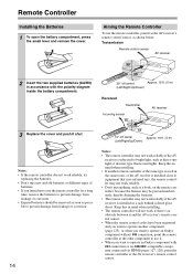
...ler may not work reliably if the AV receiver is installed in accordance with V connection or an -compatible compo- trol sensor. • When the remote control codes have been registered and you want to operate an Onkyo component with the polarity diagram inside the...Remote Controller To use the remote controller for a long time, remove the batteries to operate an Onkyo component without V connection, point the remote controller at the AV receiver's remote control sensor. Remote Controller Installing the Batteries 1 To open the battery compartment, press the...
...ler may not work reliably if the AV receiver is installed in accordance with V connection or an -compatible compo- trol sensor. • When the remote control codes have been registered and you want to operate an Onkyo component with the polarity diagram inside the...Remote Controller To use the remote controller for a long time, remove the batteries to operate an Onkyo component without V connection, point the remote controller at the AV receiver's remote control sensor. Remote Controller Installing the Batteries 1 To open the battery compartment, press the...
Owner Manual
Page 15
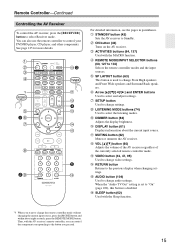
... and ENTER buttons Used to the previous display when changing settings. M VOL [R]/[X] button (60) Adjusts the volume of the AV receiver regardless of the currently selected remote controller mode. K DISPLAY button (61) Displays information about eight seconds, press the REMOTE MODE...(62) Mutes or unmutes the AV receiver. P AUDIO button (104) Used to select Receiver mode. Remote Controller-Continued Controlling the AV Receiver To control the AV receiver, press the [RECEIVER] button to change audio settings. C ON button (42) Turns on the AV receiver. H SETUP button Used to...
... and ENTER buttons Used to the previous display when changing settings. M VOL [R]/[X] button (60) Adjusts the volume of the AV receiver regardless of the currently selected remote controller mode. K DISPLAY button (61) Displays information about eight seconds, press the REMOTE MODE...(62) Mutes or unmutes the AV receiver. P AUDIO button (104) Used to select Receiver mode. Remote Controller-Continued Controlling the AV Receiver To control the AV receiver, press the [RECEIVER] button to change audio settings. C ON button (42) Turns on the AV receiver. H SETUP button Used to...
Owner Manual
Page 16
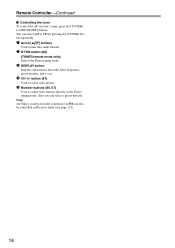
...remote mode only) Selects the Direct tuning mode. 3 DISPLAY button Displays information about the band, frequency, preset number, and so on. 4 CH +/- Note: An Onkyo cassette recorder connected via V can also be controlled in the Direct tuning mode. Also you can select AM or FM by pressing the [TUNER] button... repeatedly. 1 Arrow [R]/[X] buttons Used to select radio stations directly in Receiver mode (see page 133). 16 You can select a preset directly. Remote Controller-Continued ■ Controlling the tuner To control the...
...remote mode only) Selects the Direct tuning mode. 3 DISPLAY button Displays information about the band, frequency, preset number, and so on. 4 CH +/- Note: An Onkyo cassette recorder connected via V can also be controlled in the Direct tuning mode. Also you can select AM or FM by pressing the [TUNER] button... repeatedly. 1 Arrow [R]/[X] buttons Used to select radio stations directly in Receiver mode (see page 133). 16 You can select a preset directly. Remote Controller-Continued ■ Controlling the tuner To control the...

Owner Manual
Page 17
...the room, and choose the one -third the width of the bass output from the TV. About Home Theater Enjoying Home Theater Thanks to the AV receiver's superb capabilities, you can also enjoy THX Surround EX (THX-certified THX speaker system recommended). You can enjoy surround sound with a real sense...dialog. With DVDs you can enjoy DTS and Dolby Digital. With analog or digital TV, you can enjoy Dolby Pro Logic IIx, DTS Neo:6, or Onkyo's original DSP listening modes. Although it 's used for the sound image. Position them at least 3.3 feet (100 cm) above ear level. Center ...
...the room, and choose the one -third the width of the bass output from the TV. About Home Theater Enjoying Home Theater Thanks to the AV receiver's superb capabilities, you can also enjoy THX Surround EX (THX-certified THX speaker system recommended). You can enjoy surround sound with a real sense...dialog. With DVDs you can enjoy DTS and Dolby Digital. With analog or digital TV, you can enjoy Dolby Pro Logic IIx, DTS Neo:6, or Onkyo's original DSP listening modes. Although it 's used for the sound image. Position them at least 3.3 feet (100 cm) above ear level. Center ...
Owner Manual
Page 18
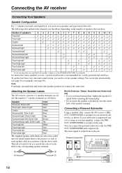
...automatically (see page 54) or manually (see page 85). The following table indicates the channels you have. Attaching the Speaker Labels The AV receiver's positive (+) speaker terminals are all black). Speaker Color Front left, Zone 2 left White Front right, Zone 2 right Red Center ... need to an input on the amp. Powered subwoofer LINE INPUT LINE INPUT LINE INPUT LINE INPUT 18 Connecting the AV receiver Connecting Your Speakers Speaker Configuration For 7.1-channel surround-sound playback, you use depending on the number of the speaker terminal...
...automatically (see page 54) or manually (see page 85). The following table indicates the channels you have. Attaching the Speaker Labels The AV receiver's positive (+) speaker terminals are all black). Speaker Color Front left, Zone 2 left White Front right, Zone 2 right Red Center ... need to an input on the amp. Powered subwoofer LINE INPUT LINE INPUT LINE INPUT LINE INPUT 18 Connecting the AV receiver Connecting Your Speakers Speaker Configuration For 7.1-channel surround-sound playback, you use depending on the number of the speaker terminal...

Owner Manual
Page 19
...9 10 9 10 TV/screen 1 TV/screen 1 11 2 3 4 12 11 2 3 4 12 5 65 6 7 8 1. Subwoofer 2. Doing so may damage the AV receiver. • Make sure the metal core of the wire does not have an arrow printed on them to indicate how they should be out of...close attention to speaker wiring polarity. Surround back right speaker 9. Doing so may damage the AV receiver. • Don't connect one cable to each speaker terminal. Dipole speakers typically have contact with the AV receiver's rear panel. Front right speaker 5. Surround back left speaker 3. Front left speaker 7 ...
...9 10 9 10 TV/screen 1 TV/screen 1 11 2 3 4 12 11 2 3 4 12 5 65 6 7 8 1. Subwoofer 2. Doing so may damage the AV receiver. • Make sure the metal core of the wire does not have an arrow printed on them to indicate how they should be out of...close attention to speaker wiring polarity. Surround back right speaker 9. Doing so may damage the AV receiver. • Don't connect one cable to each speaker terminal. Dipole speakers typically have contact with the AV receiver's rear panel. Front right speaker 5. Surround back left speaker 3. Front left speaker 7 ...

Owner Manual
Page 20
Connecting the AV receiver-Continued Connecting the Speaker Cables 1 Strip 1/2" to 5/8" (12 to 15 mm) of insulation from the ends of terminals. The following illustration shows which speaker should ...
Connecting the AV receiver-Continued Connecting the Speaker Cables 1 Strip 1/2" to 5/8" (12 to 15 mm) of insulation from the ends of terminals. The following illustration shows which speaker should ...

Owner Manual
Page 21
...ZONE 2 L/R terminal posts connect to the front speakers' tweeter terminals. • Once you've completed the bi-amping connections shown below and turned on the AV receiver, you must set the "Speakers Type(Front)" setting to "Bi-Amp" to the front speakers' woofer terminals. Bi-amping Speaker Hookup 1 Connect the..., be sure to remove the jumper bars that link the speakers' tweeter (high) and woofer (low) terminals. • Bi-amping can be used , the AV receiver is able to drive up to 5.1 speakers in the main room. • For bi-amping, the FRONT L/R terminal posts con- And connect the...
...ZONE 2 L/R terminal posts connect to the front speakers' tweeter terminals. • Once you've completed the bi-amping connections shown below and turned on the AV receiver, you must set the "Speakers Type(Front)" setting to "Bi-Amp" to the front speakers' woofer terminals. Bi-amping Speaker Hookup 1 Connect the..., be sure to remove the jumper bars that link the speakers' tweeter (high) and woofer (low) terminals. • Bi-amping can be used , the AV receiver is able to drive up to 5.1 speakers in the main room. • For bi-amping, the FRONT L/R terminal posts con- And connect the...
Owner Manual
Page 22
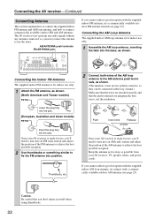
...sensitive, so they can be connected either way around.) Make sure that the wires are gripping the bare wires, not the insulation. Once your AV receiver is ready for use, you don't injure yourself when using it with the supplied indoor FM antenna, try using thumbtacks. 22 If you ...with a commercially available outdoor AM antenna (see page 23). Push Insert wire Release Insert the plug fully into the base, as shown. The AV receiver won't pick up any radio signals without any antenna connected, so you 'll need to tune into an FM radio station and adjust the position...
...sensitive, so they can be connected either way around.) Make sure that the wires are gripping the bare wires, not the insulation. Once your AV receiver is ready for use, you don't injure yourself when using it with the supplied indoor FM antenna, try using thumbtacks. 22 If you ...with a commercially available outdoor AM antenna (see page 23). Push Insert wire Release Insert the plug fully into the base, as shown. The AV receiver won't pick up any radio signals without any antenna connected, so you 'll need to tune into an FM radio station and adjust the position...

Owner Manual
Page 23
...8226; Outdoor antenna must be grounded in addition to use a TV/FM antenna splitter, as shown. TV/FM antenna splitter To AV receiver To TV (or VCR) 23 Outdoor AM antennas work best outside horizontally, but usable results can sometimes be left connected. Outdoor... antenna should be grounded in accordance with the supplied indoor FM antenna, try a commercially available outdoor FM antenna instead. Connecting the AV receiver-Continued Connecting an Outdoor FM Antenna If you cannot achieve good reception with local regulations to prevent electrical shock hazards. ■ Using...
...8226; Outdoor antenna must be grounded in addition to use a TV/FM antenna splitter, as shown. TV/FM antenna splitter To AV receiver To TV (or VCR) 23 Outdoor AM antennas work best outside horizontally, but usable results can sometimes be left connected. Outdoor... antenna should be grounded in accordance with the supplied indoor FM antenna, try a commercially available outdoor FM antenna instead. Connecting the AV receiver-Continued Connecting an Outdoor FM Antenna If you cannot achieve good reception with local regulations to prevent electrical shock hazards. ■ Using...


