
Owner Manual
Page 1
...Onkyo AV Receiver. Following the instructions in the unit. Contents Introduction 2 Connection 18 Turning On & First Time Setup .....48 Basic Operations 67 Using the Listening Modes ........81 Advanced Setup 92 NET/USB 120 Multi Zone 130 Controlling Other Components....139 Others 154 En AV Receiver TX-NR3007 TX...-NR5007 Instruction Manual Thank you to obtain optimum performance and listening enjoyment from your new AV Receiver. Please retain this manual will enable you for future ...
...Onkyo AV Receiver. Following the instructions in the unit. Contents Introduction 2 Connection 18 Turning On & First Time Setup .....48 Basic Operations 67 Using the Listening Modes ........81 Advanced Setup 92 NET/USB 120 Multi Zone 130 Controlling Other Components....139 Others 154 En AV Receiver TX-NR3007 TX...-NR5007 Instruction Manual Thank you to obtain optimum performance and listening enjoyment from your new AV Receiver. Please retain this manual will enable you for future ...
Owner Manual
Page 4
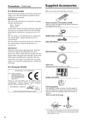
...BS1362 and have the following code: Blue: Neutral Brown: Live As the colours of the wires in compliance with the plug on the AV receiver's power cord (adapter varies from country to country.) Speaker cable labels * Power-plug adapter Only supplied in the plug. If the fuse... which is marked with an appropriate fuse. GROEBENZELL, GERMANY K. The wire which is marked with the letter N or coloured black. MIYAGI ONKYO EUROPE ELECTRONICS GmbH 1 Speaker Cable 2 FRONT LEFT FRONT LEFT FRONT RIGHT FRONT RIGHT SURROUND LEFT SURROUND LEFT SURROUND RIGHT SURROUND RIGHT CENTER CENTER...
...BS1362 and have the following code: Blue: Neutral Brown: Live As the colours of the wires in compliance with the plug on the AV receiver's power cord (adapter varies from country to country.) Speaker cable labels * Power-plug adapter Only supplied in the plug. If the fuse... which is marked with an appropriate fuse. GROEBENZELL, GERMANY K. The wire which is marked with the letter N or coloured black. MIYAGI ONKYO EUROPE ELECTRONICS GmbH 1 Speaker Cable 2 FRONT LEFT FRONT LEFT FRONT RIGHT FRONT RIGHT SURROUND LEFT SURROUND LEFT SURROUND RIGHT SURROUND RIGHT CENTER CENTER...
Owner Manual
Page 5
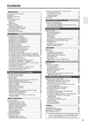
...139 Preprogrammed Remote Control Codes 139 Looking up for Remote Control Code 139 Entering Remote Control Codes 141 Remote Control Codes for Onkyo Components Connected via V 142 Resetting REMOTE MODE Buttons 142 Resetting the Remote Controller 142 Controlling a TV 143 Controlling a ... Recorder 149 Activities Setup 150 Learning Commands 152 Using Normal Macros 153 Others Troubleshooting 154 Specifications (TX-NR3007 160 Specifications (TX-NR5007 161 Video Resolution Chart 162 * To reset the AV receiver to its factory defaults, turn it on and, while holding down the [VCR/DVR] button...
...139 Preprogrammed Remote Control Codes 139 Looking up for Remote Control Code 139 Entering Remote Control Codes 141 Remote Control Codes for Onkyo Components Connected via V 142 Resetting REMOTE MODE Buttons 142 Resetting the Remote Controller 142 Controlling a TV 143 Controlling a ... Recorder 149 Activities Setup 150 Learning Commands 152 Using Normal Macros 153 Others Troubleshooting 154 Specifications (TX-NR3007 160 Specifications (TX-NR5007 161 Video Resolution Chart 162 * To reset the AV receiver to its factory defaults, turn it on and, while holding down the [VCR/DVR] button...
Owner Manual
Page 8
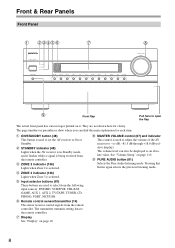
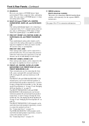
...indicator (136) Lights when Zone 2 is selected. G Remote control sensor/transmitter (14) The sensor receives control signals from the remote controller. B ON/STANDBY button (48) This button is used to set the AV receiver to select from the following input sources: DVD/BD, VCR/DVR, CBL/SAT, GAME, AUX 1,...flap The actual front panel has various logos printed on it flashes while a signal is being received from the remote controller. C STANDBY indicator (48) Lights when the AV receiver is in parentheses show where you can also be displayed as an absolute value. The transmitter ...
...indicator (136) Lights when Zone 2 is selected. G Remote control sensor/transmitter (14) The sensor receives control signals from the remote controller. B ON/STANDBY button (48) This button is used to set the AV receiver to select from the following input sources: DVD/BD, VCR/DVR, CBL/SAT, GAME, AUX 1,...flap The actual front panel has various logos printed on it flashes while a signal is being received from the remote controller. C STANDBY indicator (48) Lights when the AV receiver is in parentheses show where you can also be displayed as an absolute value. The transmitter ...

Owner Manual
Page 10
...There are outputted for composite video, analog audio, and optical digital audio. It must be played through the AV receiver. The following abbreviations indicate which speaker set the AV receiver to connect a camcorder, game console, and so on. LW: Front wide left LH: Front high ... input source. Lights when the "Equalizer Settings" is selected: A or B. B Speaker/channel indicators Indicate the speaker channels used to OFF, the AV receiver is enabled. Vol (101, 118): Lights when "Dolby Volume" is completely shutdown. B CDE F G HI JK L For detailed information, see...
...There are outputted for composite video, analog audio, and optical digital audio. It must be played through the AV receiver. The following abbreviations indicate which speaker set the AV receiver to connect a camcorder, game console, and so on. LW: Front wide left LH: Front high ... input source. Lights when the "Equalizer Settings" is selected: A or B. B Speaker/channel indicators Indicate the speaker channels used to OFF, the AV receiver is enabled. Vol (101, 118): Lights when "Dolby Volume" is completely shutdown. B CDE F G HI JK L For detailed information, see...

Owner Manual
Page 11
... Input Setup" on page 56. 11 AUTO (73): Lights when Auto Tuning mode is set . C IR IN/OUT A commercially available IR receiver can assign each one to an input selector to "Bi-Amp". I SLEEP indicator (69) Lights when the Sleep function has been set to...to a stereo FM station. TUNED (73): Lights when tuned to control the AV receiver while you to a radio station. P MUTING indicator (69) Flashes while the AV receiver is muted. D DIGITAL OPTICAL IN 1 and 2 (TX-NR3007) DIGITAL OPTICAL IN 1, 2, and 3 (TX-NR5007) These optical digital audio inputs are plugged into the PHONES jack.
... Input Setup" on page 56. 11 AUTO (73): Lights when Auto Tuning mode is set . C IR IN/OUT A commercially available IR receiver can assign each one to an input selector to "Bi-Amp". I SLEEP indicator (69) Lights when the Sleep function has been set to...to a stereo FM station. TUNED (73): Lights when tuned to control the AV receiver while you to a radio station. P MUTING indicator (69) Flashes while the AV receiver is muted. D DIGITAL OPTICAL IN 1 and 2 (TX-NR3007) DIGITAL OPTICAL IN 1, 2, and 3 (TX-NR5007) These optical digital audio inputs are plugged into the PHONES jack.

Owner Manual
Page 12
... (RCA) between the AV receiver and the other end of the power cord should be connected to a video input on a component in here and the music selected can be connected to an V jack on a TV in Zone 3. J HDMI IN 1-6, OUT MAIN, and OUT SUB (TX-NR3007) HDMI IN 1-7, OUT... and analog audio. They're assignable, which means you can be connected to a video input on another Onkyo AV component. H V REMOTE CONTROL This V (Remote Interactive) jack can be played through the AV receiver. The HDMI inputs are for connecting components with an HDMI output, such as a DVD player, DVD recorder...
... (RCA) between the AV receiver and the other end of the power cord should be connected to a video input on a component in here and the music selected can be connected to an V jack on a TV in Zone 3. J HDMI IN 1-6, OUT MAIN, and OUT SUB (TX-NR3007) HDMI IN 1-7, OUT... and analog audio. They're assignable, which means you can be connected to a video input on another Onkyo AV component. H V REMOTE CONTROL This V (Remote Interactive) jack can be played through the AV receiver. The HDMI inputs are for connecting components with an HDMI output, such as a DVD player, DVD recorder...
Owner Manual
Page 13
... line inputs on a multichannel power amplifier for when you can be used with front speakers B and surround back speakers respectively, or used to use the AV receiver solely as a DVD player, DVD-Audio or Super Audio CD-capable player, or an MPEG decoder. See "Connecting Zone 3" on page 24. See "Bi-amping...
... line inputs on a multichannel power amplifier for when you can be used with front speakers B and surround back speakers respectively, or used to use the AV receiver solely as a DVD player, DVD-Audio or Super Audio CD-capable player, or an MPEG decoder. See "Connecting Zone 3" on page 24. See "Bi-amping...

Owner Manual
Page 14
... types of the same type is used in the same room, or the AV receiver is installed in mind when installing. • If another component (page 141), or when you want to operate an Onkyo component with the polarity diagram inside the battery compartment. 3 Replace the cover ...and push it shut. 30° off center Approx. 16 ft. (5 m) (Left/Right/Up/Down) Received Transmitter Incoming sensor 15 AV receiver 15 15° off center Approx. 16 ft....
... types of the same type is used in the same room, or the AV receiver is installed in mind when installing. • If another component (page 141), or when you want to operate an Onkyo component with the polarity diagram inside the battery compartment. 3 Replace the cover ...and push it shut. 30° off center Approx. 16 ft. (5 m) (Left/Right/Up/Down) Received Transmitter Incoming sensor 15 AV receiver 15 15° off center Approx. 16 ft....
Owner Manual
Page 15
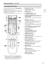
...to select and adjust settings. Q SLEEP button (69) Used with the MACRO function. Remote Controller-Continued Controlling the AV Receiver To control the AV receiver, press the [RECEIVER] button to 149) Selects the remote controller modes and the input sources. See page 141 for more details. ... Used with the Sleep function. 15 You can select the combination of the currently selected remote controller mode. Then, with the AV receiver's remote controller, you can control the component corresponding to select the listening modes. H SETUP button Used to change settings. B STANDBY...
...to select and adjust settings. Q SLEEP button (69) Used with the MACRO function. Remote Controller-Continued Controlling the AV Receiver To control the AV receiver, press the [RECEIVER] button to 149) Selects the remote controller modes and the input sources. See page 141 for more details. ... Used with the Sleep function. 15 You can select the combination of the currently selected remote controller mode. Then, with the AV receiver's remote controller, you can control the component corresponding to select the listening modes. H SETUP button Used to change settings. B STANDBY...

Owner Manual
Page 16
Also you can also be controlled in the Direct tuning mode. Note: An Onkyo cassette recorder connected via V can select a preset directly. button (74) Used to select radio presets. 5 Number buttons (73, 74) Used to tune into radio stations. ...Displays information about the band, frequency, preset number, and so on. 4 CH +/- Remote Controller-Continued ■ Controlling the tuner To control the AV receiver's tuner, press the [TUNER] (or [RECEIVER]) button. You can select AM or FM by pressing the [TUNER] button repeatedly. 1 Arrow [R]/[X] buttons Used to select radio stations directly in...
Also you can also be controlled in the Direct tuning mode. Note: An Onkyo cassette recorder connected via V can select a preset directly. button (74) Used to select radio presets. 5 Number buttons (73, 74) Used to tune into radio stations. ...Displays information about the band, frequency, preset number, and so on. 4 CH +/- Remote Controller-Continued ■ Controlling the tuner To control the AV receiver's tuner, press the [TUNER] (or [RECEIVER]) button. You can select AM or FM by pressing the [TUNER] button repeatedly. 1 Arrow [R]/[X] buttons Used to select radio stations directly in...

Owner Manual
Page 17
... sound and improve sound localization behind , about 2 to 3 feet (60 to 100 cm) above ear level. About Home Theater Enjoying Home Theater Thanks to the AV receiver's superb capabilities, you can enjoy surround sound with a real sense of movement in your TV facing forward at about ear level, or at the same.... With DVDs you can also enjoy THX Surround EX (THX-certified THX speaker system recommended). You can enjoy Dolby Pro Logic IIx, DTS Neo:6, or Onkyo's original DSP listening modes.
... sound and improve sound localization behind , about 2 to 3 feet (60 to 100 cm) above ear level. About Home Theater Enjoying Home Theater Thanks to the AV receiver's superb capabilities, you can enjoy surround sound with a real sense of movement in your TV facing forward at about ear level, or at the same.... With DVDs you can also enjoy THX Surround EX (THX-certified THX speaker system recommended). You can enjoy Dolby Pro Logic IIx, DTS Neo:6, or Onkyo's original DSP listening modes.

Owner Manual
Page 18
.... When bridging or bi-amping is used for serious music listening with a pair of highpower stereo speakers, the subwoofer is used , the AV receiver can drive up to 26 for use Speakers B for enjoying DVD movies, while Speakers B is used with a pair of top-quality stereo...Type(FrontB) Powered Zone2 Powered Zone3 8ohms Normal BTL Not Act Not Act 2-2. Connecting the AV receiver Connecting Your Speakers About Speakers A and Speakers B Speakers A and Speakers B allows you can configure the AV receiver to 5.2 speakers in the main room. The speakers are bridged, front Speakers B can...
.... When bridging or bi-amping is used for serious music listening with a pair of highpower stereo speakers, the subwoofer is used , the AV receiver can drive up to 26 for use Speakers B for enjoying DVD movies, while Speakers B is used with a pair of top-quality stereo...Type(FrontB) Powered Zone2 Powered Zone3 8ohms Normal BTL Not Act Not Act 2-2. Connecting the AV receiver Connecting Your Speakers About Speakers A and Speakers B Speakers A and Speakers B allows you can configure the AV receiver to 5.2 speakers in the main room. The speakers are bridged, front Speakers B can...
Owner Manual
Page 19
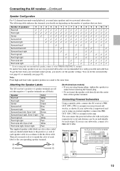
... center hole of speakers that you have. To get the best from your subwoofer is to match the color of each output. Connecting the AV receiver-Continued Speaker Configuration For 9.2-channel surround-sound playback, you need to set individually for a really powerful and solid bass. You can connect the... (+) side of each jacks respectively. Level and distance can be set the speaker settings. Connecting Powered Subwoofers Using a suitable cable, connect the AV receiver's PRE OUT: SW1, SW2 to an input on your powered subwoofer, as shown. Attaching the Speaker Labels The...
... center hole of speakers that you have. To get the best from your subwoofer is to match the color of each output. Connecting the AV receiver-Continued Speaker Configuration For 9.2-channel surround-sound playback, you need to set individually for a really powerful and solid bass. You can connect the... (+) side of each jacks respectively. Level and distance can be set the speaker settings. Connecting Powered Subwoofers Using a suitable cable, connect the AV receiver's PRE OUT: SW1, SW2 to an input on your powered subwoofer, as shown. Attaching the Speaker Labels The...
Owner Manual
Page 20
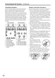
...impedance to "4ohms" (see page 57). Surround left and right speakers. Dipole speakers output the same sound in protection circuit may damage the AV receiver. • Don't connect more than 6 ohms, be activated. • Disconnect the power cord from the wall outlet before connecting your speakers...If you use dipole speakers for a long period of time, the built-in two directions. In other , as shown. Connecting the AV receiver-Continued Using Dipole Speakers You can connect speakers with an impedance of between 4 and 16 ohms. If the impedance of any connections. ...
...impedance to "4ohms" (see page 57). Surround left and right speakers. Dipole speakers output the same sound in protection circuit may damage the AV receiver. • Don't connect more than 6 ohms, be activated. • Disconnect the power cord from the wall outlet before connecting your speakers...If you use dipole speakers for a long period of time, the built-in two directions. In other , as shown. Connecting the AV receiver-Continued Using Dipole Speakers You can connect speakers with an impedance of between 4 and 16 ohms. If the impedance of any connections. ...

Owner Manual
Page 21
... the terminal tight. ■ 9.2-channel Playback with Speakers A The following illustration shows which speaker should be connected to the SURR BACK/ZONE 3 L terminal. Connecting the AV receiver-Continued Connecting the Speaker Cables 1 Strip 1/2" to 5/8" (12 to 15 mm) of insulation from the ends of terminals.
... the terminal tight. ■ 9.2-channel Playback with Speakers A The following illustration shows which speaker should be connected to the SURR BACK/ZONE 3 L terminal. Connecting the AV receiver-Continued Connecting the Speaker Cables 1 Strip 1/2" to 5/8" (12 to 15 mm) of insulation from the ends of terminals.
Owner Manual
Page 22
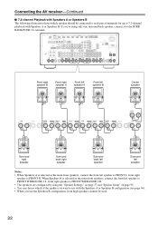
... using the "Speaker Settings" on page 57 and "Speaker Setup" on page 95. • You can choose which speaker should be used. 22 Connecting the AV receiver-Continued ■ 7.2-channel Playback with Speakers A or Speakers B The following illustration shows which of the spakers you want to use the Speakers B configuration, front high...
... using the "Speaker Settings" on page 57 and "Speaker Setup" on page 95. • You can choose which speaker should be used. 22 Connecting the AV receiver-Continued ■ 7.2-channel Playback with Speakers A or Speakers B The following illustration shows which of the spakers you want to use the Speakers B configuration, front high...
Owner Manual
Page 23
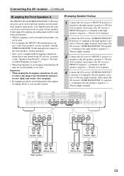
... When making the bi-amping connections, be sure to the right speaker's positive (+) Woofer (low) terminal. Bi-amping Speaker Hookup 1 Connect the AV receiver's FRONT R positive (+) terminal to remove the jumper bars that link the Speakers' tweeter (high) and woofer (low) terminals. • Bi-amping... Woofer (low) terminal. Refer to provide separate tweeter and woofer feeds for a pair of front speakers A that support bi-amping. Connecting the AV receiver-Continued Bi-amping the Front Speakers A The FRONT L/R and SURR BACK/ZONE 3 L/R terminal posts can be used with speakers that support bi...
... When making the bi-amping connections, be sure to the right speaker's positive (+) Woofer (low) terminal. Bi-amping Speaker Hookup 1 Connect the AV receiver's FRONT R positive (+) terminal to remove the jumper bars that link the Speakers' tweeter (high) and woofer (low) terminals. • Bi-amping... Woofer (low) terminal. Refer to provide separate tweeter and woofer feeds for a pair of front speakers A that support bi-amping. Connecting the AV receiver-Continued Bi-amping the Front Speakers A The FRONT L/R and SURR BACK/ZONE 3 L/R terminal posts can be used with speakers that support bi...
Owner Manual
Page 24
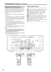
... can be wired normally or not used. Right speaker Left speaker 24 And connect the AV receiver's SURR BACK/ZONE 3 R positive (+) terminal to the right speaker's negative (-) terminal. 2 Connect the AV receiver's FRONT L positive (+) terminal to enable bridging (see page 57). • When front... you've completed the bridging connections shown below and turned on the AV receiver, you must set the "Speakers Type(FrontA)" setting to "BTL" to the left speaker's negative (-) terminal. Connecting the AV receiver-Continued Bridging the Front Speakers A The FRONT L/R and SURR BACK/ZONE...
... can be wired normally or not used. Right speaker Left speaker 24 And connect the AV receiver's SURR BACK/ZONE 3 R positive (+) terminal to the right speaker's negative (-) terminal. 2 Connect the AV receiver's FRONT L positive (+) terminal to enable bridging (see page 57). • When front... you've completed the bridging connections shown below and turned on the AV receiver, you must set the "Speakers Type(FrontA)" setting to "BTL" to the left speaker's negative (-) terminal. Connecting the AV receiver-Continued Bridging the Front Speakers A The FRONT L/R and SURR BACK/ZONE...

Owner Manual
Page 25
... • For bi-amping, the FRONT WIDE/ZONE 2 L/R ter- Bi-amping Speaker Hookup 1 Connect the AV receiver's FRONT WIDE/ZONE 2 R positive (+) terminal to your speaker manual. And connect the AV receiver's SURR BACK/ZONE 3 L negative (-) terminal to provide separate tweeter and woofer feeds for a pair of front ... terminal posts connect to the front speakers' tweeter terminals. • Once you've completed the bi-amping connections shown below and turned on the AV receiver, you must set the "Speakers Type(FrontB)" setting to "Bi-Amp" to enable biamping (see page 57). • When front Speakers ...
... • For bi-amping, the FRONT WIDE/ZONE 2 L/R ter- Bi-amping Speaker Hookup 1 Connect the AV receiver's FRONT WIDE/ZONE 2 R positive (+) terminal to your speaker manual. And connect the AV receiver's SURR BACK/ZONE 3 L negative (-) terminal to provide separate tweeter and woofer feeds for a pair of front ... terminal posts connect to the front speakers' tweeter terminals. • Once you've completed the bi-amping connections shown below and turned on the AV receiver, you must set the "Speakers Type(FrontB)" setting to "Bi-Amp" to enable biamping (see page 57). • When front Speakers ...


