
Owner Manual
Page 1
... 36 Recording a source 37 Using TAPE-2 MONITOR 40 Selecting a Surround mode 42 Setting the Surround mode parameters 44 TX-DS838 parameters 46 Troubleshooting guide 47 Specifications 49 Artistry in Sound ONKYQ Audio Video Control Receiver TX-DS838 Instruction Manual = = 00 o 0 *O 1 I I I 1 I I OOO All models except European models ... the power 17 Connecting antennas 18 Setting up the Multi-Room Remote System 20 Multi-Room Remote Control .22 Using the on-screen display function (remote control only) ......... ..„. 23 Setting up the speaker system 26...
... 36 Recording a source 37 Using TAPE-2 MONITOR 40 Selecting a Surround mode 42 Setting the Surround mode parameters 44 TX-DS838 parameters 46 Troubleshooting guide 47 Specifications 49 Artistry in Sound ONKYQ Audio Video Control Receiver TX-DS838 Instruction Manual = = 00 o 0 *O 1 I I I 1 I I OOO All models except European models ... the power 17 Connecting antennas 18 Setting up the Multi-Room Remote System 20 Multi-Room Remote Control .22 Using the on-screen display function (remote control only) ......... ..„. 23 Setting up the speaker system 26...
Owner Manual
Page 4
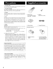
... report this , dry immediately with a soft cloth. ply voltage of the region where they are trademarks of the power supply in your Onkyo authorized service station. 4. The memory preservation period after the last time the unit has been unplugged. Care From time to time you should... Recording of the memory during power failures and even when the unit is unplugged. The unit must be used in a weak solution of the unit. 1 Remote control U.S. & Canada: RC-P101S Other areas: RC-P201S 1 AM loop antenna Worldwide model only: 1 75/300 ohm antenna adaptor 2 Batteries (size AA, R6,...
... report this , dry immediately with a soft cloth. ply voltage of the region where they are trademarks of the power supply in your Onkyo authorized service station. 4. The memory preservation period after the last time the unit has been unplugged. Care From time to time you should... Recording of the memory during power failures and even when the unit is unplugged. The unit must be used in a weak solution of the unit. 1 Remote control U.S. & Canada: RC-P101S Other areas: RC-P201S 1 AM loop antenna Worldwide model only: 1 75/300 ohm antenna adaptor 2 Batteries (size AA, R6,...
Owner Manual
Page 5
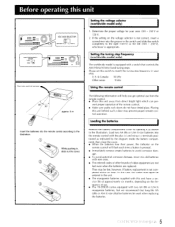
... the battery compartment, then close the cover. • When the batteries lose their power, the indicator on the remote control will help you get optimal use . • The TX-DS838 comes equipped with the plus (+) and minus (-) terminals positioned as shown in your area: 220 - 230 V ...or 120 V. 2. Determine the proper voltage for your area. U.S. & Canada: 10 kHz Other areas: 9 kHz Using the remote control The following information will flash...
... the battery compartment, then close the cover. • When the batteries lose their power, the indicator on the remote control will help you get optimal use . • The TX-DS838 comes equipped with the plus (+) and minus (-) terminals positioned as shown in your area: 220 - 230 V ...or 120 V. 2. Determine the proper voltage for your area. U.S. & Canada: 10 kHz Other areas: 9 kHz Using the remote control The following information will flash...
Owner Manual
Page 7
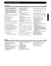
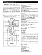
... adjusts the volume of a soundtrack. Turning it will light up for the selected speakers lights up each time a signal is received from the remote control. • Remote control sensor [5] ® AC-3 indicator [42] C) DIMMER button Used to change the brightness of the display in four steps (bright, medium,...) indicator C) Source indicators © MULTI SOURCE indicator 7 Depending on the display are: -O. The volume can not be adjusted using the remote control's VOL A/V buttons. Even if the knob is set the MASTER VOLUME level to select the desired AC-3 or PRO LOGIC Surround mode. Use ...
... adjusts the volume of a soundtrack. Turning it will light up for the selected speakers lights up each time a signal is received from the remote control. • Remote control sensor [5] ® AC-3 indicator [42] C) DIMMER button Used to change the brightness of the display in four steps (bright, medium,...) indicator C) Source indicators © MULTI SOURCE indicator 7 Depending on the display are: -O. The volume can not be adjusted using the remote control's VOL A/V buttons. Even if the knob is set the MASTER VOLUME level to select the desired AC-3 or PRO LOGIC Surround mode. Use ...
Owner Manual
Page 8
...pressed, the timer automatically starts and the SLEEP indicator on the display lights up each time a button on the remote control is pressed. ® POWER button Switches the TX-DS838 between stand-by status (the STAND-BY/ RECEIVED indicator is displayed, 10 minutes are always available regardless of this... equipment if the correct device code is not turned off and on how to control it from TAPE-1, TUNER or CD. The remote control can be used to operate components equipped with an Onkyo RI (Remote Interactive) connector and connected to adjust the volume level of the display in the...
...pressed, the timer automatically starts and the SLEEP indicator on the display lights up each time a button on the remote control is pressed. ® POWER button Switches the TX-DS838 between stand-by status (the STAND-BY/ RECEIVED indicator is displayed, 10 minutes are always available regardless of this... equipment if the correct device code is not turned off and on how to control it from TAPE-1, TUNER or CD. The remote control can be used to operate components equipped with an Onkyo RI (Remote Interactive) connector and connected to adjust the volume level of the display in the...
Owner Manual
Page 9
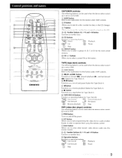
... following buttons can be used when the device select switch is set to CD/TUNER. © SLEEP button Refer to the explanation for this remote control. (D-g Number buttons (0, 1-9) and +10 button Function as number keys. C) CD buttons Function as a reverse playback button for the tuner preset memory.... device codes of other brands' video device codes into this button under AMP controls. ® 11,► and 10-10- C) CH +1- button Functions as a stop button for discs in order to operate them using this remote control. © Enter button Allows you to enter other brands in the CD...
... following buttons can be used when the device select switch is set to CD/TUNER. © SLEEP button Refer to the explanation for this remote control. (D-g Number buttons (0, 1-9) and +10 button Function as number keys. C) CD buttons Function as a reverse playback button for the tuner preset memory.... device codes of other brands' video device codes into this button under AMP controls. ® 11,► and 10-10- C) CH +1- button Functions as a stop button for discs in order to operate them using this remote control. © Enter button Allows you to enter other brands in the CD...
Owner Manual
Page 11
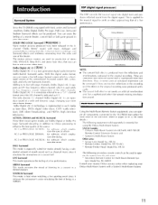
...: • The concert hal l effect is a new-generation digital audio format for using the Onkyo Multi-Room System: USA & Canada: * Onkyo's Multi-Room System kits HKT-600, HKT-700 (IR Remote Control Extension System) and Xantech's Multi-Room System Other area: * Sensor Unit: Model No. HE-...These are used to as a "5.1" channel format since this digital audio format, you can operate all components connected to the TX-DS838 from the sub-room: * Secondary Remote Control for media already having a substantial amount of a live performance. tem: Model No. AC-3 or PRO LOGIC ACTION: for...
...: • The concert hal l effect is a new-generation digital audio format for using the Onkyo Multi-Room System: USA & Canada: * Onkyo's Multi-Room System kits HKT-600, HKT-700 (IR Remote Control Extension System) and Xantech's Multi-Room System Other area: * Sensor Unit: Model No. HE-...These are used to as a "5.1" channel format since this digital audio format, you can operate all components connected to the TX-DS838 from the sub-room: * Secondary Remote Control for media already having a substantial amount of a live performance. tem: Model No. AC-3 or PRO LOGIC ACTION: for...
Owner Manual
Page 12
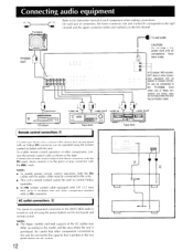
...other component equipped with this unit do not exceed the capacity that are being used to control Onkyo turntables. • An RI remote control cable equipped with 1/8" (3.5 mm) mini jacks is printed on and off using the remote control included with an optical or coaxial connector can be operated using the power buttons on ..., both the RI cables and the audio cables must be connected to the units. • This unit's remote control cannot be connected to the TX-DS838. Even when one of the AC outlets may differ according to the model and the area where the unit is turned on the ...
...other component equipped with this unit do not exceed the capacity that are being used to control Onkyo turntables. • An RI remote control cable equipped with 1/8" (3.5 mm) mini jacks is printed on and off using the remote control included with an optical or coaxial connector can be operated using the power buttons on ..., both the RI cables and the audio cables must be connected to the units. • This unit's remote control cannot be connected to the TX-DS838. Even when one of the AC outlets may differ according to the model and the area where the unit is turned on the ...
Owner Manual
Page 17
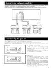
...the power, be used in power-on the remote control is used in the unit, confirm that the MASTER VOLUME control knob is fully turned counterclockwise. POWER switch FIB . The POWER button on status (the unit can be used to operate the TX-DS838 if the SYSTEM switch is not set to... is lit). With such amplifiers, you to the stand-by status (the STAND-BY/RECEIVED indicator is lit). Turning on the remote control switches the TX-DS838 between standby status (the STAND-BY/RECEIVED indicator is lit) and poweron status (the SYSTEM indicator is lit). Connecting optional amplifiers The...
...the power, be used in power-on the remote control is used in the unit, confirm that the MASTER VOLUME control knob is fully turned counterclockwise. POWER switch FIB . The POWER button on status (the unit can be used to operate the TX-DS838 if the SYSTEM switch is not set to... is lit). With such amplifiers, you to the stand-by status (the STAND-BY/RECEIVED indicator is lit). Turning on the remote control switches the TX-DS838 between standby status (the STAND-BY/RECEIVED indicator is lit) and poweron status (the SYSTEM indicator is lit). Connecting optional amplifiers The...
Owner Manual
Page 20
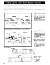
... sub-room, then connect it to the TX-DS838. (,4)) (Connect the AC adaptor to the TXDS838. Connecting block Remote control SUB ROOM _5. Components(d) TX-DS838 Connec ing block 1. Make the connections described above : 4. Setting up the Onkyo RI components (a). 2. IR Receiver, Dinky Link or J-Box Receiver 1. Connect the TX-DS838 to the TX-DS838. 5. Be sure the components are in...
... sub-room, then connect it to the TX-DS838. (,4)) (Connect the AC adaptor to the TXDS838. Connecting block Remote control SUB ROOM _5. Components(d) TX-DS838 Connec ing block 1. Make the connections described above : 4. Setting up the Onkyo RI components (a). 2. IR Receiver, Dinky Link or J-Box Receiver 1. Connect the TX-DS838 to the TX-DS838. 5. Be sure the components are in...
Owner Manual
Page 21
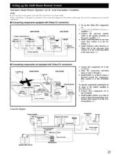
... Remote control Speaker (Sub room) Remote Sensor Speaker (Sub room) N--1 1. PRE OUT L, MRx IN I ). Be sure the components are correctly connected. • Connecting components equipped with Onkyo RI connectors 3. Connecting block N \H_ Power supply 2. Speaker \ Sub room) 1. Connect the TX-DS838 to the speaker terminals on the power amplifier. (E2_;) 4. Connect the components (b) to the TX-DS838. 5. Components(d) TX-DS838...
... Remote control Speaker (Sub room) Remote Sensor Speaker (Sub room) N--1 1. PRE OUT L, MRx IN I ). Be sure the components are correctly connected. • Connecting components equipped with Onkyo RI connectors 3. Connecting block N \H_ Power supply 2. Speaker \ Sub room) 1. Connect the TX-DS838 to the speaker terminals on the power amplifier. (E2_;) 4. Connect the components (b) to the TX-DS838. 5. Components(d) TX-DS838...
Owner Manual
Page 22
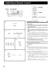
...from another room In the main room: 1. In the sub-room, direct the remote control toward that component. • Check that the components are correctly connected. • Check that the MR OFF indicator on the TX-DS838 to pages 20 and 21 for connection details. Use the VOLUME • or V... directed toward the Remote Sensor (Onkyo multi-room system) and: 5. cator go off. (If the MR OFF indicator is lit, the multi-room system cannot be used from the sub-room, but the components cannot be controlled, check the following: • Use the controls on the remote control to select your...
...from another room In the main room: 1. In the sub-room, direct the remote control toward that component. • Check that the components are correctly connected. • Check that the MR OFF indicator on the TX-DS838 to pages 20 and 21 for connection details. Use the VOLUME • or V... directed toward the Remote Sensor (Onkyo multi-room system) and: 5. cator go off. (If the MR OFF indicator is lit, the multi-room system cannot be used from the sub-room, but the components cannot be controlled, check the following: • Use the controls on the remote control to select your...
Owner Manual
Page 23
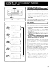
... on the TV/monitor. (For example, if the cable connected to MONITOR OUTPUT is not recorded, even if an on-screen display appears on the remote control to the Surround mode selected. N F' N J 4 ~Coo), 5 CONNESeICIP * I ra no N NE1C.CID * • • s , o7o ns , ME L NE NP El ... is output only to display the selected screen. 4. Using the on-screen display function remo e con ro on the remote control. 3. Basic operation Use the remote control to move the cursor to IESC in each screen differ according to display the Menu screen. 2. Press the P. cursor button...
... on the TV/monitor. (For example, if the cable connected to MONITOR OUTPUT is not recorded, even if an on-screen display appears on the remote control to the Surround mode selected. N F' N J 4 ~Coo), 5 CONNESeICIP * I ra no N NE1C.CID * • • s , o7o ns , ME L NE NP El ... is output only to display the selected screen. 4. Using the on-screen display function remo e con ro on the remote control. 3. Basic operation Use the remote control to move the cursor to IESC in each screen differ according to display the Menu screen. 2. Press the P. cursor button...
Owner Manual
Page 24
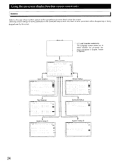
... un inn ROI E101 ESC un CIE . Menu off * U.S. Selecting certain settings for more details about the screen. p A rci Using the on-screen display function (remote control only) Screens Refer to select whether the on-screen displays will appear in other parameters either disappearing or being skipped over by the cursor. p . and... for some parameters in the Surround Setup screen may result in English, French or Spanish. vIDP, • VID I I , C• * * * ESC Input Selector ctar.rxc-tirot ONKYO 1 Rec Selector -.
... un inn ROI E101 ESC un CIE . Menu off * U.S. Selecting certain settings for more details about the screen. p A rci Using the on-screen display function (remote control only) Screens Refer to select whether the on-screen displays will appear in other parameters either disappearing or being skipped over by the cursor. p . and... for some parameters in the Surround Setup screen may result in English, French or Spanish. vIDP, • VID I I , C• * * * ESC Input Selector ctar.rxc-tirot ONKYO 1 Rec Selector -.
Owner Manual
Page 25
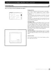
... colors may differ depending on the TV/monitor's tone and brightness settings. Using the on-screen display function (remote control only) Screen Setup screen When Screen Setup is selected, the following screen appears: 10.1\TX.,C40. ** Screen Setup ** Background Color A BLUE -1 Color 3 = GREEN GB Superimpose Mode = NORMAL GM Smmediate Display , ON BrI Character...
... colors may differ depending on the TV/monitor's tone and brightness settings. Using the on-screen display function (remote control only) Screen Setup screen When Screen Setup is selected, the following screen appears: 10.1\TX.,C40. ** Screen Setup ** Background Color A BLUE -1 Color 3 = GREEN GB Superimpose Mode = NORMAL GM Smmediate Display , ON BrI Character...

Owner Manual
Page 26
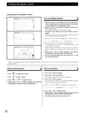
...y , e , Seeup 3 4C61, INE -IM ** Sys7e, Setup • A ** ESC cearet Set pmac a ce e t_ a b r a cor.Tx.c.sro, ** s t_ en Set_ op 3 ** Balance Cort e -to select Balance Control, and then press the IP- Setting up the speaker systems System Setup A: System Setup B: Select this parameter and enter settings.... 7. Refer to select System Setup. 2. to display the Menu screen. 2. Repeat step 4. Press the ENTER button on the remote control to enter the settings for more details on page 28. Refer to System Setup screen on page 27 for the Speaker Distance parameters....
...y , e , Seeup 3 4C61, INE -IM ** Sys7e, Setup • A ** ESC cearet Set pmac a ce e t_ a b r a cor.Tx.c.sro, ** s t_ en Set_ op 3 ** Balance Cort e -to select Balance Control, and then press the IP- Setting up the speaker systems System Setup A: System Setup B: Select this parameter and enter settings.... 7. Refer to select System Setup. 2. to display the Menu screen. 2. Repeat step 4. Press the ENTER button on the remote control to enter the settings for more details on page 28. Refer to System Setup screen on page 27 for the Speaker Distance parameters....

Owner Manual
Page 27
... set the speaker parameters for more details. Speaker Distance Use this parameter to OFF. 27 Refer to Calibrating the speaker levels on the remote control to the film director's intentions. System Setup A and B have the same parameter settings, it is set to NO, only OFF ... mode can be shown in meters (the settings will change in 1 foot steps). NOTE: • Since all Surround modes. CI _ COZWI.C`ICCD * Sceeke to OFF. ONKYO -1- = A -,eft LeVei Sc T ( pHgei el ESC _ • 7d 51 51 -5dB 55 2 d n 1 (=I Center Speaker settings LARGE: Select when using a...
... set the speaker parameters for more details. Speaker Distance Use this parameter to OFF. 27 Refer to Calibrating the speaker levels on the remote control to the film director's intentions. System Setup A and B have the same parameter settings, it is set to NO, only OFF ... mode can be shown in meters (the settings will change in 1 foot steps). NOTE: • Since all Surround modes. CI _ COZWI.C`ICCD * Sceeke to OFF. ONKYO -1- = A -,eft LeVei Sc T ( pHgei el ESC _ • 7d 51 51 -5dB 55 2 d n 1 (=I Center Speaker settings LARGE: Select when using a...
Owner Manual
Page 28
... 11 ONKYO * T,eve Calibration * ESC Ssasting - The test signal sounds from the left front speaker. 3. r With each press of the button, the selected speaker changes one at a time in the System Setup A screen, and then press the PP' cursor button on the remote control to adjust...em Se,up A ** Speaker Setup p Speaker DSstance p ever. Sign 0.1•TNE.Sr•=1. Press the • cursor button on the remote control to adjust all speaker levels until the test signal level sounds the same from all speakers. 1. Press CTESDT to adjust all speaker levels until the...
... 11 ONKYO * T,eve Calibration * ESC Ssasting - The test signal sounds from the left front speaker. 3. r With each press of the button, the selected speaker changes one at a time in the System Setup A screen, and then press the PP' cursor button on the remote control to adjust...em Se,up A ** Speaker Setup p Speaker DSstance p ever. Sign 0.1•TNE.Sr•=1. Press the • cursor button on the remote control to adjust all speaker levels until the test signal level sounds the same from all speakers. 1. Press CTESDT to adjust all speaker levels until the...

Owner Manual
Page 29
...source. Adjust the volume to the appropriate level using a Surround mode, refer to pages 42 to 45. 4. Adjust the tone controls. TREBLE control knob Adjusts the treble response. Remote control and main unit operation 2 1 4 6 O®, 000 0O a. Press the input selector button for the selected unit to...pages 42 to 45 for more details on the display. Press the A or B speaker selector button to OFF, the remote control cannot be used. 2. DIGITAL I 3 0 0 1. BASS control knob Adjusts the bass response. European models only: If the SYSTEM switch on using the tuner. 6. When the CD ...
...source. Adjust the volume to the appropriate level using a Surround mode, refer to pages 42 to 45. 4. Adjust the tone controls. TREBLE control knob Adjusts the treble response. Remote control and main unit operation 2 1 4 6 O®, 000 0O a. Press the input selector button for the selected unit to...pages 42 to 45 for more details on the display. Press the A or B speaker selector button to OFF, the remote control cannot be used. 2. DIGITAL I 3 0 0 1. BASS control knob Adjusts the bass response. European models only: If the SYSTEM switch on using the tuner. 6. When the CD ...
Owner Manual
Page 30
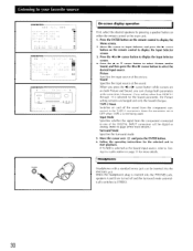
... display the Input Selector screen. 3. Move the cursor to Input Selector and press the ► cursor button on either the remote control or the main unit. 1. Picture Specifies the input source of the sound. Switches on both parameters at the same time. Input Mode Specifies ...-src, * "no , - Press the -4 or IP- When the headphones plug is selected as the Sound input source, refer to Tuning in a radio station on the remote control to display the Menu screen. 2. C A TAP H - -;' Mop . . = OFF Tdout Mode = ANAL,OC Sdrrouod Mode- TAPE-2 Moni. Move the cursor over es. Keep this ...
... display the Input Selector screen. 3. Move the cursor to Input Selector and press the ► cursor button on either the remote control or the main unit. 1. Picture Specifies the input source of the sound. Switches on both parameters at the same time. Input Mode Specifies ...-src, * "no , - Press the -4 or IP- When the headphones plug is selected as the Sound input source, refer to Tuning in a radio station on the remote control to display the Menu screen. 2. C A TAP H - -;' Mop . . = OFF Tdout Mode = ANAL,OC Sdrrouod Mode- TAPE-2 Moni. Move the cursor over es. Keep this ...


