
English Manual
Page 2
TABLE OF CONTENTS IMPORTANT PRECAUTIONS 3 BEFORE YOU BEGIN 4 ASSEMBLY 5 CABLE DIAGRAM 21 ADJUSTMENTS 22 WEIGHT RESISTANCE CHART 24 TROUBLE-SHOOTING AND MAINTENANCE 25 EXERCISE GUIDELINES 26 ORDERING REPLACEMENT PARTS Back Cover LIMITED WARRANTY Back Cover Note: A PART IDENTIFICATION CHART and a PART LIST/EXPLODED DRAWING are attached in the center of ICON Health & Fitness, Inc. 2 Remove the PART IDENTIFICATION CHART and PART LIST/EXPLODED DRAWING before beginning assembly. NordicTrack is a registered trademark of this manual.
TABLE OF CONTENTS IMPORTANT PRECAUTIONS 3 BEFORE YOU BEGIN 4 ASSEMBLY 5 CABLE DIAGRAM 21 ADJUSTMENTS 22 WEIGHT RESISTANCE CHART 24 TROUBLE-SHOOTING AND MAINTENANCE 25 EXERCISE GUIDELINES 26 ORDERING REPLACEMENT PARTS Back Cover LIMITED WARRANTY Back Cover Note: A PART IDENTIFICATION CHART and a PART LIST/EXPLODED DRAWING are attached in the center of ICON Health & Fitness, Inc. 2 Remove the PART IDENTIFICATION CHART and PART LIST/EXPLODED DRAWING before beginning assembly. NordicTrack is a registered trademark of this manual.
English Manual
Page 11
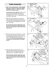
...(92), a 3/8" Washer (55), and a 3/8" Nylon Locknut (50). Wrap the Leg Press Cable (76) around a 4" Pulley (35). Attach the Leg Press Cable to identify the cables and for correct cable routing. Refer to the CABLE DIAGRAM on page 21 to the indicated hole in the direction shown, and that the... Cable Trap (44) is positioned to the Rear Leg Press Upright (97) with a 3/8" x 3" ...
...(92), a 3/8" Washer (55), and a 3/8" Nylon Locknut (50). Wrap the Leg Press Cable (76) around a 4" Pulley (35). Attach the Leg Press Cable to identify the cables and for correct cable routing. Refer to the CABLE DIAGRAM on page 21 to the indicated hole in the direction shown, and that the... Cable Trap (44) is positioned to the Rear Leg Press Upright (97) with a 3/8" x 3" ...

English Manual
Page 21
Incorrect cable routing can damage the weight system. 8 10 11 2 1 High Cable (73) 9 6 7 4 3 5 64 6 12 4 3 Leg Press Cable (76) Cable ID Chart 53 5 1 -76 -72 -73 21 2 2 1 Low Cable (72) Large Ball Make sure that the cables are routed correctly, that the pulleys move smoothly, and that the cable traps do not touch or bind the cables. The numbers show the correct route for each cable. CABLE DIAGRAM The diagram below shows the proper routing of the Low Cable (72), the High Cable (73), and the Leg Press Cable (76).
Incorrect cable routing can damage the weight system. 8 10 11 2 1 High Cable (73) 9 6 7 4 3 5 64 6 12 4 3 Leg Press Cable (76) Cable ID Chart 53 5 1 -76 -72 -73 21 2 2 1 Low Cable (72) Large Ball Make sure that the cables are routed correctly, that the pulleys move smoothly, and that the cable traps do not touch or bind the cables. The numbers show the correct route for each cable. CABLE DIAGRAM The diagram below shows the proper routing of the Low Cable (72), the High Cable (73), and the Leg Press Cable (76).


