
English Manual
Page 1
The trained technicians on our customer hot line will guarantee complete satisfaction through direct assistance from our factory. USER'S MANUAL Visit our website at www.nordictrack.com new products, prizes, fitness tips, and much more! Write the serial number in the location shown below. Serial... Number Decal QUESTIONS? TO AVOID DELAYS, PLEASE CALL DIRECT TO OUR TOLLFREE CUSTOMER HOT LINE. Save this ...
The trained technicians on our customer hot line will guarantee complete satisfaction through direct assistance from our factory. USER'S MANUAL Visit our website at www.nordictrack.com new products, prizes, fitness tips, and much more! Write the serial number in the location shown below. Serial... Number Decal QUESTIONS? TO AVOID DELAYS, PLEASE CALL DIRECT TO OUR TOLLFREE CUSTOMER HOT LINE. Save this ...
English Manual
Page 11
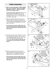
... Leg Press Upright (97) with a 3/8" x 3 3/4" Bolt (92), a 3/8" Washer (55), and a 3/8" Nylon Locknut (50). Be sure that the Leg Press Cable (76) is routed in the direction shown, and that the Cable Trap (44) is positioned to hold the Cable in the pulley groove. 18 76 50 55 44 92 35 84... 92 35 44 76 50 55 18. Locate the Leg Press Cable (76). Be sure that the Leg Press Cable (76) is routed in the direction shown, and that the Cable Trap (44) is positioned to hold the Cable in the Leg Press Base (84) with a 3/8" Nylon Locknut (50). Route the...
... Leg Press Upright (97) with a 3/8" x 3 3/4" Bolt (92), a 3/8" Washer (55), and a 3/8" Nylon Locknut (50). Be sure that the Leg Press Cable (76) is routed in the direction shown, and that the Cable Trap (44) is positioned to hold the Cable in the pulley groove. 18 76 50 55 44 92 35 84... 92 35 44 76 50 55 18. Locate the Leg Press Cable (76). Be sure that the Leg Press Cable (76) is routed in the direction shown, and that the Cable Trap (44) is positioned to hold the Cable in the Leg Press Base (84) with a 3/8" Nylon Locknut (50). Route the...
English Manual
Page 13
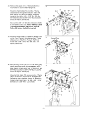
... the Main Upright (3). Route the High Cable (73) under the welded tube 24 on the Press Frame (12) and around another 4" Pulley (35) in the direction shown. Attach the Pulley to the Press Frame (12) with a 3/8" x 8 1/2" Bolt (59) and a 3/8" Nylon Locknut (50). 25 35 42 63 55 Slot 50 54 42...
... the Main Upright (3). Route the High Cable (73) under the welded tube 24 on the Press Frame (12) and around another 4" Pulley (35) in the direction shown. Attach the Pulley to the Press Frame (12) with a 3/8" x 8 1/2" Bolt (59) and a 3/8" Nylon Locknut (50). 25 35 42 63 55 Slot 50 54 42...
English Manual
Page 14
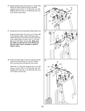
... a 3/8" Nylon Jamnut (63). Route the High Cable (73) up through the Top Frame. Make sure the Cable is in the groove of holes in the direction shown. Attach the 4" Pulley (35) inside the slot in the Top Frame (1), over a 4" Pulley (35), and back down through the indicated slot in the Main...
... a 3/8" Nylon Jamnut (63). Route the High Cable (73) up through the Top Frame. Make sure the Cable is in the groove of holes in the direction shown. Attach the 4" Pulley (35) inside the slot in the Top Frame (1), over a 4" Pulley (35), and back down through the indicated slot in the Main...
English Manual
Page 15
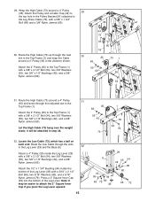
... 42 96 80 35 72 Let the High Cable (73) hang over the weight stack; Route the Low Cable through the indicated slot in the direction shown. Note: It may be attached in the Leg Lever (29) and the Base (8). 32 Attach a 4" Pulley (35) inside the bottom of the Leg Lever...
... 42 96 80 35 72 Let the High Cable (73) hang over the weight stack; Route the Low Cable through the indicated slot in the direction shown. Note: It may be attached in the Leg Lever (29) and the Base (8). 32 Attach a 4" Pulley (35) inside the bottom of the Leg Lever...
English Manual
Page 16
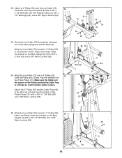
... third set of holes from the bottom of the Pulley and that the Cable Trap is oriented so it will hold the Cable in the direction shown. Wrap the Low Cable (72) around a 4" Pulley (35) in place. Make sure the Cable is in the Main Upright (3) and the Base (8). Attach a 4" Pulley...
... third set of holes from the bottom of the Pulley and that the Cable Trap is oriented so it will hold the Cable in the direction shown. Wrap the Low Cable (72) around a 4" Pulley (35) in place. Make sure the Cable is in the Main Upright (3) and the Base (8). Attach a 4" Pulley...
