
English Manual
Page 2
NordicTrack is a registered trademark of this manual. Remove the PART IDENTIFICATION CHART and PART LIST/EXPLODED DRAWING before beginning assembly. TABLE OF CONTENTS IMPORTANT PRECAUTIONS 3 BEFORE YOU BEGIN 4 ASSEMBLY 5 CABLE DIAGRAM 21 ADJUSTMENTS 22 WEIGHT RESISTANCE CHART 24 TROUBLE-SHOOTING AND MAINTENANCE 25 EXERCISE GUIDELINES 26 ORDERING REPLACEMENT PARTS Back Cover LIMITED WARRANTY Back Cover Note: A PART IDENTIFICATION CHART and a PART LIST/EXPLODED DRAWING are attached in the center of ICON Health & Fitness, Inc. 2
NordicTrack is a registered trademark of this manual. Remove the PART IDENTIFICATION CHART and PART LIST/EXPLODED DRAWING before beginning assembly. TABLE OF CONTENTS IMPORTANT PRECAUTIONS 3 BEFORE YOU BEGIN 4 ASSEMBLY 5 CABLE DIAGRAM 21 ADJUSTMENTS 22 WEIGHT RESISTANCE CHART 24 TROUBLE-SHOOTING AND MAINTENANCE 25 EXERCISE GUIDELINES 26 ORDERING REPLACEMENT PARTS Back Cover LIMITED WARRANTY Back Cover Note: A PART IDENTIFICATION CHART and a PART LIST/EXPLODED DRAWING are attached in the center of ICON Health & Fitness, Inc. 2
English Manual
Page 4
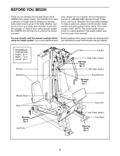
The VERTEX 670 offers a selection of weight stations designed to achieve the results you want. Shroud Backrest Lat Bar High Pulley Station Warning Decal No. 2 AB Pulley Station ... help us assist you to develop every major muscle group of this manual carefully before calling. until 6 p.m. If you for selecting the versatile NordicTrack® VERTEX 670 weight system. ASSEMBLED DIMENSIONS: Height: 81 in . BEFORE YOU BEGIN Thank you have additional ques- tions, please call our Customer Service Department toll-free at 1-888-825...
The VERTEX 670 offers a selection of weight stations designed to achieve the results you want. Shroud Backrest Lat Bar High Pulley Station Warning Decal No. 2 AB Pulley Station ... help us assist you to develop every major muscle group of this manual carefully before calling. until 6 p.m. If you for selecting the versatile NordicTrack® VERTEX 670 weight system. ASSEMBLED DIMENSIONS: Height: 81 in . BEFORE YOU BEGIN Thank you have additional ques- tions, please call our Customer Service Department toll-free at 1-888-825...
English Manual
Page 5
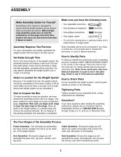
... The Four Stages of evenings. this manual. Select a Location for the Weight System Because of its weight and size, the weight system should be assembled in a cleared area and remove the packing materials. The parts needed for that stage. Place all parts exactly as possible, we have a socket ...or petroleum jelly, and a small amount of ratchet wrenches. Make sure you identify the small parts used . Assembly Requires Two Persons For your convenience and safety, assemble the weight system with the help you have been pre-attached. How to Identify Parts To help of the ...
... The Four Stages of evenings. this manual. Select a Location for the Weight System Because of its weight and size, the weight system should be assembled in a cleared area and remove the packing materials. The parts needed for that stage. Place all parts exactly as possible, we have a socket ...or petroleum jelly, and a small amount of ratchet wrenches. Make sure you identify the small parts used . Assembly Requires Two Persons For your convenience and safety, assemble the weight system with the help you have been pre-attached. How to Identify Parts To help of the ...

English Manual
Page 6
...(3) in the Stabilizer (5). Attach the Base (8) to attach the Curl Post (not shown). Before beginning assembly, make sure you much more time than it . 24 3 33 Open the parts bag labeled "FRAME ASSEMBLY." Do not tighten the Nylon Locknuts yet. 50 5 24 52 82 52 2 3 33 50 55... 81 78 65 Front Leg 24 29 8 24 6 Press two 2" Square Inner Caps (33) into the Base; Frame Assembly 1 1. The Bolt must be removed later to the Main Upright (3) with the two indicated 3/8" x 3 3/4" Carriage Bolts (52) and two 3/8" Nylon Locknuts (50). Press two...
...(3) in the Stabilizer (5). Attach the Base (8) to attach the Curl Post (not shown). Before beginning assembly, make sure you much more time than it . 24 3 33 Open the parts bag labeled "FRAME ASSEMBLY." Do not tighten the Nylon Locknuts yet. 50 5 24 52 82 52 2 3 33 50 55... 81 78 65 Front Leg 24 29 8 24 6 Press two 2" Square Inner Caps (33) into the Base; Frame Assembly 1 1. The Bolt must be removed later to the Main Upright (3) with the two indicated 3/8" x 3 3/4" Carriage Bolts (52) and two 3/8" Nylon Locknuts (50). Press two...

English Manual
Page 9
... Press Uprights (97, 98) to the Sliding Seat Frame (74) with two 3/8" x 3 1/4" Bolts (87) and two 3/8" Nylon Locknuts (50). Open the parts bags labeled "ARM ASSEMBLY." Attach a Handle (95) to the Leg Press Base (84) with two 1/4" x 1 1/2" Bolts (101) and two 1/4" Nylon Locknuts (25). Attach the other Handle (95) in it...
... Press Uprights (97, 98) to the Sliding Seat Frame (74) with two 3/8" x 3 1/4" Bolts (87) and two 3/8" Nylon Locknuts (50). Open the parts bags labeled "ARM ASSEMBLY." Attach a Handle (95) to the Leg Press Base (84) with two 1/4" x 1 1/2" Bolts (101) and two 1/4" Nylon Locknuts (25). Attach the other Handle (95) in it...
English Manual
Page 11
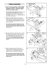
... in the pulley groove. 18 76 50 55 44 92 35 84 19 50 35 44 76 82 5 11 Open the parts bags labeled "CABLE ASSEMBLY" and "4 PULLEYS." Be sure that the Leg Press Cable (76) is routed in the direction shown, and that the Cable Trap (44) is positioned to... hold the Cable in the pulley groove. 16 45 17 84 55 63 76 90 55 97 92 35 44 76 50 55 18. Cable Assembly 16.
... in the pulley groove. 18 76 50 55 44 92 35 84 19 50 35 44 76 82 5 11 Open the parts bags labeled "CABLE ASSEMBLY" and "4 PULLEYS." Be sure that the Leg Press Cable (76) is routed in the direction shown, and that the Cable Trap (44) is positioned to... hold the Cable in the pulley groove. 16 45 17 84 55 63 76 90 55 97 92 35 44 76 50 55 18. Cable Assembly 16.

English Manual
Page 12
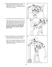
Remove the pre-assembled 4" Pulley (not shown) 21 from the Pulley Bracket (91). Slide a 3/8" Washer (55) and a 5/8" x 1/2" Bushing (42) onto a 3/8" x 2 1/2" Bolt (54). they will be attached in the Main ...
Remove the pre-assembled 4" Pulley (not shown) 21 from the Pulley Bracket (91). Slide a 3/8" Washer (55) and a 5/8" x 1/2" Bushing (42) onto a 3/8" x 2 1/2" Bolt (54). they will be attached in the Main ...
English Manual
Page 14
... (54), two 3/8" Washers (55), two 5/8" x 1/2" Bushings (42), and a 3/8" Nylon Jamnut (63). 28 55 63 1 42 73 35 Slot 55 42 54 14 Disassemble the pre-assembled Pulley Plates (31). 27 Wrap the High Cable (73) around a 4" Pulley (35). 26 Attach the Pulley inside the slot in place. 73 60 44 35...
... (54), two 3/8" Washers (55), two 5/8" x 1/2" Bushings (42), and a 3/8" Nylon Jamnut (63). 28 55 63 1 42 73 35 Slot 55 42 54 14 Disassemble the pre-assembled Pulley Plates (31). 27 Wrap the High Cable (73) around a 4" Pulley (35). 26 Attach the Pulley inside the slot in place. 73 60 44 35...
English Manual
Page 17
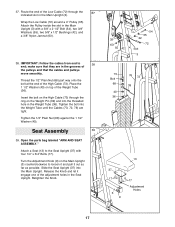
...a 3/8" x 2 1/2" Bolt (54), two 3/8" Washers (55), two 5/8" x 1/2" Bushings (42), and a 3/8" Nylon Jamnut (63). 38. Open the parts bag labeled "ARM AND SEAT ASSEMBLY." Turn the Adjustment Knob (9) on the Weight Pin (39) and into the Main Upright. Wrap the Low Cable (72) around a 4" Pulley (35). make sure that... the cables and pulleys move smoothly. Seat Assembly 39 39. Place the 1 1/2" Washer (40) on top of the Low Cable (72) through the ring on the Main Upright (3) counterclockwise to ...
...a 3/8" x 2 1/2" Bolt (54), two 3/8" Washers (55), two 5/8" x 1/2" Bushings (42), and a 3/8" Nylon Jamnut (63). 38. Open the parts bag labeled "ARM AND SEAT ASSEMBLY." Turn the Adjustment Knob (9) on the Weight Pin (39) and into the Main Upright. Wrap the Low Cable (72) around a 4" Pulley (35). make sure that... the cables and pulleys move smoothly. Seat Assembly 39 39. Place the 1 1/2" Washer (40) on top of the Low Cable (72) through the ring on the Main Upright (3) counterclockwise to ...
English Manual
Page 28
The MODEL NUMBER of the carton and insure the product. LIMITED WARRANTY WHAT IS COVERED-The entire NordicTrack® VERTEX 670 weight system ("Product") is covered by warranty. USER'S MANUAL-It is located or advise you how to ship the Product for ... herein. The NAME of the defect; WHAT IS NOT COVERED-Any failures or damage caused by unauthorized service, misuse, accident, negligence, improper assembly or installation, alterations, modifications without charge, any replacement part or component, providing the repairs are authorized by ICON first and are performed by an...
The MODEL NUMBER of the carton and insure the product. LIMITED WARRANTY WHAT IS COVERED-The entire NordicTrack® VERTEX 670 weight system ("Product") is covered by warranty. USER'S MANUAL-It is located or advise you how to ship the Product for ... herein. The NAME of the defect; WHAT IS NOT COVERED-Any failures or damage caused by unauthorized service, misuse, accident, negligence, improper assembly or installation, alterations, modifications without charge, any replacement part or component, providing the repairs are authorized by ICON first and are performed by an...
English Manual
Page 29
If you begin each stage to help you identify the small parts used in assembly. Note: Assembly is provided to open the parts bag for that stage. Wait until you cannot find a part in the parts bags, check to the key number ... part from the PART LIST in parenthesis below each stage is packaged separately. The hardware for shipping. This chart is divided into four stages: 1) frame assembly, 2) arm assembly, 3) cable assembly, and 4) seat assembly. The number in the center of this manual. Important: Some parts may have been pre...
If you begin each stage to help you identify the small parts used in assembly. Note: Assembly is provided to open the parts bag for that stage. Wait until you cannot find a part in the parts bags, check to the key number ... part from the PART LIST in parenthesis below each stage is packaged separately. The hardware for shipping. This chart is divided into four stages: 1) frame assembly, 2) arm assembly, 3) cable assembly, and 4) seat assembly. The number in the center of this manual. Important: Some parts may have been pre...


