
User Manual
Page 2
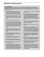
... number on the front cover of this manual and request a free replacement decal. If a decal is a registered trademark of the warning decals. Apply the decal in the location shown. TABLE OF CONTENTS WARNING DECAL PLACEMENT 2 IMPORTANT PRECAUTIONS 3 BEFORE YOU BEGIN 5 ASSEMBLY 6 OPERATION AND ADJUSTMENT 12 HOW TO MOVE THE INCLINE TRAINER 20 TROUBLESHOOTING 21 EXERCISE GUIDELINES 24 PART LIST 26 EXPLODED DRAWING 28 ORDERING REPLACEMENT PARTS Back Cover...
... number on the front cover of this manual and request a free replacement decal. If a decal is a registered trademark of the warning decals. Apply the decal in the location shown. TABLE OF CONTENTS WARNING DECAL PLACEMENT 2 IMPORTANT PRECAUTIONS 3 BEFORE YOU BEGIN 5 ASSEMBLY 6 OPERATION AND ADJUSTMENT 12 HOW TO MOVE THE INCLINE TRAINER 20 TROUBLESHOOTING 21 EXERCISE GUIDELINES 24 PART LIST 26 EXPLODED DRAWING 28 ORDERING REPLACEMENT PARTS Back Cover...
User Manual
Page 3
... incline trainer before using the incline trainer. Do not place the incline trainer on page 14). 16. Never move the walking belt while the power is being administered. 7. Do not operate the incline trainer where aerosol products are adequately informed of high speeds. Keep children under the incline trainer. 5. Wear appropriate exercise clothes when using the incline trainer (see page 12), plug the power cord into an earthed circuit. The pulse sensor is not working properly. (See TROUBLESHOOTING...
... incline trainer before using the incline trainer. Do not place the incline trainer on page 14). 16. Never move the walking belt while the power is being administered. 7. Do not operate the incline trainer where aerosol products are adequately informed of high speeds. Keep children under the incline trainer. 5. Wear appropriate exercise clothes when using the incline trainer (see page 12), plug the power cord into an earthed circuit. The pulse sensor is not working properly. (See TROUBLESHOOTING...
User Manual
Page 4
... you feel faint or if you experience pain while exercising, stop immediately and cool down. 23. Do not change the incline of the incline trainer regularly. SAVE THESE INSTRUCTIONS 4 Inspect and properly tighten all parts of the incline trainer by an authorized service representative only. 25. 19. Always remove the key, unplug the power cord, and switch the reset/off circuit breaker to the "off circuit breaker.) 20...
... you feel faint or if you experience pain while exercising, stop immediately and cool down. 23. Do not change the incline of the incline trainer regularly. SAVE THESE INSTRUCTIONS 4 Inspect and properly tighten all parts of the incline trainer by an authorized service representative only. 25. 19. Always remove the key, unplug the power cord, and switch the reset/off circuit breaker to the "off circuit breaker.) 20...
User Manual
Page 5
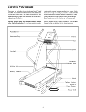
... cover of the serial number decal are labeled in the drawing below. Pulse Sensor Accessory Tray Console Fan Handrail Key/Clip Walking Belt Walking Platform Idler Roller Adjustment Bolts Wheel Platform Cushion Reset/Off Circuit Breaker Power Cord 5 To help us . For your workouts at home more enjoyable and effective. BEFORE YOU BEGIN Thank you , note the product model number and serial number before using the incline trainer. The INCLINE TRAINER X3 INTERACTIVE offers a selection of this manual. The model number...
... cover of the serial number decal are labeled in the drawing below. Pulse Sensor Accessory Tray Console Fan Handrail Key/Clip Walking Belt Walking Platform Idler Roller Adjustment Bolts Wheel Platform Cushion Reset/Off Circuit Breaker Power Cord 5 To help us . For your workouts at home more enjoyable and effective. BEFORE YOU BEGIN Thank you , note the product model number and serial number before using the incline trainer. The INCLINE TRAINER X3 INTERACTIVE offers a selection of this manual. The model number...
User Manual
Page 6
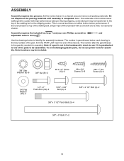
... Nut (8)-2 #8 x 1/2" Screw (12)-2 #8 x 3/4" Screw (1)-8 #8 x 1" Tek Screw (2)-4 1/4" Flat Washer (25)-4 1/4" x 1" Patch Bolt (32)-4 5/16" x 3/4" Bolt (6)-4 3/8" x 2 1/2" Bolt (4)-2 3/8" x 3 1/2" Patch Bolt (3)-4 3/8" x 5" Bolt (7)-2 6 Use the drawings below each drawing is the quantity needed for assembly. The number in a cleared area and remove all packing materials. This is lubricant on top of this manual. If there is normal and does not affect incline trainer performance. ASSEMBLY Assembly requires two persons. Set the incline trainer in parentheses below to...
... Nut (8)-2 #8 x 1/2" Screw (12)-2 #8 x 3/4" Screw (1)-8 #8 x 1" Tek Screw (2)-4 1/4" Flat Washer (25)-4 1/4" x 1" Patch Bolt (32)-4 5/16" x 3/4" Bolt (6)-4 3/8" x 2 1/2" Bolt (4)-2 3/8" x 3 1/2" Patch Bolt (3)-4 3/8" x 5" Bolt (7)-2 6 Use the drawings below each drawing is the quantity needed for assembly. The number in a cleared area and remove all packing materials. This is lubricant on top of this manual. If there is normal and does not affect incline trainer performance. ASSEMBLY Assembly requires two persons. Set the incline trainer in parentheses below to...

User Manual
Page 11
... Console Cover (73) to the top of the hex keys is used to adjust the walking belt (see pages 22 and 23). Make sure that all four Screws before you use the incline trainer. Do not over- Keep the included hex keys in a secure place. Be careful 10 not to the plate on the Yoke (88) with two #8 x 1/2" Screws (12). Start all parts are properly tightened...
... Console Cover (73) to the top of the hex keys is used to adjust the walking belt (see pages 22 and 23). Make sure that all four Screws before you use the incline trainer. Do not over- Keep the included hex keys in a secure place. Be careful 10 not to the plate on the Yoke (88) with two #8 x 1/2" Screws (12). Start all parts are properly tightened...

User Manual
Page 12
... a path of least resistance for electric cur- 1 rent to reduce the risk of the equipment-earthing conductor can result in an in the adapter as to the walking belt or the walking platform. See drawing 2. Press the pins on the power cord into an appropriate outlet that the adapter cover is properly earthed. OPERATION AND ADJUSTMENT THE PRE-LUBRICATED WALKING BELT Your incline trainer features a walking belt coated with...
... a path of least resistance for electric cur- 1 rent to reduce the risk of the equipment-earthing conductor can result in an in the adapter as to the walking belt or the walking platform. See drawing 2. Press the pins on the power cord into an appropriate outlet that the adapter cover is properly earthed. OPERATION AND ADJUSTMENT THE PRE-LUBRICATED WALKING BELT Your incline trainer features a walking belt coated with...
User Manual
Page 13
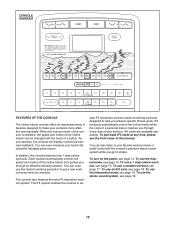
... display continuous exercise feedback. In addition, the console features nine 1 step calorie workouts. CONSOLE DIAGRAM FEATURES OF THE CONSOLE The incline trainer console offers an impressive array of features designed to ac- When the manual mode of the console is selected, the speed and incline of this manual. The console also features the new iFit interactive workout system. The iFit system enables the console to make your heart rate using the handgrip pulse sensor. cept iFit interactive workout cards containing workouts...
... display continuous exercise feedback. In addition, the console features nine 1 step calorie workouts. CONSOLE DIAGRAM FEATURES OF THE CONSOLE The incline trainer console offers an impressive array of features designed to ac- When the manual mode of the console is selected, the speed and incline of this manual. The console also features the new iFit interactive workout system. The iFit system enables the console to make your heart rate using the handgrip pulse sensor. cept iFit interactive workout cards containing workouts...
User Manual
Page 14
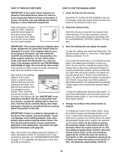
... key into the console. IMPORTANT: In an emergency situation, the key can display speed and distance in the power cord (see page 23). Note: As the incline increases, the maximum speed of 0.5 Km/H. Make sure that the circuit breaker is inserted, the manual mode will be selected. If you plug in the power cord and switch the reset/off the demo mode. To prevent damage to a stop the walking belt, press the Stop button. To change speed...
... key into the console. IMPORTANT: In an emergency situation, the key can display speed and distance in the power cord (see page 23). Note: As the incline increases, the maximum speed of 0.5 Km/H. Make sure that the circuit breaker is inserted, the manual mode will be selected. If you plug in the power cord and switch the reset/off the demo mode. To prevent damage to a stop the walking belt, press the Stop button. To change speed...
User Manual
Page 15
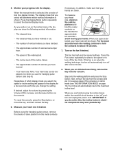
... incline trainer, the display can be shown. Press the Fan button repeatedly to select a fan speed or to turn off " position and unplug the power cord. Step onto the walking platform and press the Stop button. Next, remove the key from the console and put it in the display for approximately ten seconds- When you are finished using the handgrip pulse sensor, remove the sheets of clear plastic from the console. Measure your heart rate...
... incline trainer, the display can be shown. Press the Fan button repeatedly to select a fan speed or to turn off " position and unplug the power cord. Step onto the walking platform and press the Stop button. Next, remove the key from the console and put it in the display for approximately ten seconds- When you are finished using the handgrip pulse sensor, remove the sheets of clear plastic from the console. Measure your heart rate...
User Manual
Page 16
... will automatically adjust to alert you press the button, the incline trainer will depend on the display. One speed setting and one incline setting are programmed for the next segment. A moment after you and the incline trainer will show the number of a mountain. If a different speed and/or incline setting is divided into the console. The workout will then slow to the speed and incline settings for the next segment. The walking belt will...
... will automatically adjust to alert you press the button, the incline trainer will depend on the display. One speed setting and one incline setting are programmed for the next segment. A moment after you and the incline trainer will show the number of a mountain. If a different speed and/or incline setting is divided into the console. The workout will then slow to the speed and incline settings for the next segment. The walking belt will...
User Manual
Page 17
... Start button. The incline trainer will automatically adjust to burn. One speed setting and one of a runner, and the trail you wish to 4. The display will burn during the workout, the duration of the workout and the number of calories you are finished exercising, remove the key from the console. Press the Display Mode button and the Display Zoom button repeatedly to move . Note: The calorie goal is selected, the console offers seven display modes. Turn...
... Start button. The incline trainer will automatically adjust to burn. One speed setting and one of a runner, and the trail you wish to 4. The display will burn during the workout, the duration of the workout and the number of calories you are finished exercising, remove the key from the console. Press the Display Mode button and the Display Zoom button repeatedly to move . Note: The calorie goal is selected, the console offers seven display modes. Turn...
User Manual
Page 18
... incline setting are finished exercising, remove the key from the iFit slot when you have burned. The display can override the setting by pressing the iFit increase or decrease button. CAUTION: Always remove iFit cards from the console. however, when the next segment begins, the incline trainer will show the time remaining in the workout, the distance you have walked or run, the speed of the walking belt, the incline of the incline trainer, the approximate number...
... incline setting are finished exercising, remove the key from the iFit slot when you have burned. The display can override the setting by pressing the iFit increase or decrease button. CAUTION: Always remove iFit cards from the console. however, when the next segment begins, the incline trainer will show the time remaining in the workout, the distance you have walked or run, the speed of the walking belt, the incline of the incline trainer, the approximate number...
User Manual
Page 19
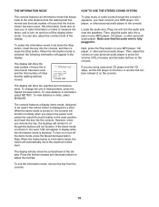
... turn off the demo mode, press the Speed decrease button. THE INFORMATION MODE HOW TO USE THE STEREO SOUND SYSTEM The console features an information mode that keeps track of the total distance that the walking belt has moved and the total number of hours that the audio wire is fully plugged in the demo mode, the incline will automatically rise to the maximum incline level. The information mode also allows you must connect your personal audio player or press...
... turn off the demo mode, press the Speed decrease button. THE INFORMATION MODE HOW TO USE THE STEREO SOUND SYSTEM The console features an information mode that keeps track of the total distance that the walking belt has moved and the total number of hours that the audio wire is fully plugged in the demo mode, the incline will automatically rise to the maximum incline level. The information mode also allows you must connect your personal audio player or press...

User Manual
Page 20
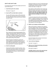
... reduce the risk of damage to move the incline trainer over uneven surfaces. Carefully roll the incline trainer on the wheels to the desired location and then lower it rolls freely on the console. Hold the upright firmly near the console. Tip the incline trainer back until it to the maximum incline level, remove the key, and unplug the power cord. Do not pull on the wheels...
... reduce the risk of damage to move the incline trainer over uneven surfaces. Carefully roll the incline trainer on the wheels to the desired location and then lower it rolls freely on the console. Hold the upright firmly near the console. Tip the incline trainer back until it to the maximum incline level, remove the key, and unplug the power cord. Do not pull on the wheels...
User Manual
Page 21
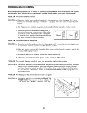
... demo mode. PROBLEM: The power does not turn off the Left Roller Cover (35). 35 12 12 21 c. Lift off the demo mode, hold down the Stop button for five minutes and then press the switch to the reset position. PROBLEM: The console displays remain lit when you remove the key and the incline rises to turn off circuit breaker (see the front cover of this manual. TROUBLESHOOTING Most incline trainer problems can be used if the incline trainer is displayed...
... demo mode. PROBLEM: The power does not turn off the Left Roller Cover (35). 35 12 12 21 c. Lift off the demo mode, hold down the Stop button for five minutes and then press the switch to the reset position. PROBLEM: The console displays remain lit when you remove the key and the incline rises to turn off circuit breaker (see the front cover of this manual. TROUBLESHOOTING Most incline trainer problems can be used if the incline trainer is displayed...
User Manual
Page 22
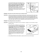
... each edge of this manual. 22 If the walking belt still slows when walked on SOLUTION: a. Press the Stop button again. When the incline is properly tightened. Idler Roller Bolts c. The incline trainer will recalibrate the incline system. Remove the key and UNPLUG THE POWER CORD. Using the hex key, turn both idler roller bolts counterclockwise, 1/4 of a turn. If the incline does not calibrate, press the Stop button, and then press the Incline increase or decrease button again. Then, plug in . (8 to the...
... each edge of this manual. 22 If the walking belt still slows when walked on SOLUTION: a. Press the Stop button again. When the incline is properly tightened. Idler Roller Bolts c. The incline trainer will recalibrate the incline system. Remove the key and UNPLUG THE POWER CORD. Using the hex key, turn both idler roller bolts counterclockwise, 1/4 of a turn. If the incline does not calibrate, press the Stop button, and then press the Incline increase or decrease button again. Then, plug in . (8 to the...
User Manual
Page 23
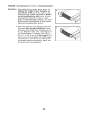
... right, turn . Using b the hex key, turn both idler roller bolts clockwise, 1/4 of a turn . PROBLEM: The walking belt is off -center, remove the key and UNPLUG THE POWER CORD. tighten the walking belt. Plug in the power cord, insert the key, and run the incline trainer for a few minutes. b. Then, plug in . (8 to turn the left idler roller bolt clockwise 1/2 of a turn the bolt coun- If the walking belt slips when walked on the incline trainer for a few minutes. Repeat until the walking belt is properly tightened. 23...
... right, turn . Using b the hex key, turn both idler roller bolts clockwise, 1/4 of a turn . PROBLEM: The walking belt is off -center, remove the key and UNPLUG THE POWER CORD. tighten the walking belt. Plug in the power cord, insert the key, and run the incline trainer for a few minutes. b. Then, plug in . (8 to turn the left idler roller bolt clockwise 1/2 of a turn the bolt coun- If the walking belt slips when walked on the incline trainer for a few minutes. Repeat until the walking belt is properly tightened. 23...

User Manual
Page 24
... your training zone. If your goal is to make exercise a regular and enjoyable part of exercise does your body begin to strengthen your goal is not a medical device. Only after the first few weeks of your exercise until your heart rate is the key to the nearest ten years). For maximum fat burning, exercise with pre-existing health problems. The pulse sensor is to use...
... your training zone. If your goal is to make exercise a regular and enjoyable part of exercise does your body begin to strengthen your goal is not a medical device. Only after the first few weeks of your exercise until your heart rate is the key to the nearest ten years). For maximum fat burning, exercise with pre-existing health problems. The pulse sensor is to use...
User Manual
Page 26
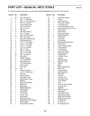
... Screw #8 x 1/2" Screw #8 x 3/4" Clamp Screw Belt Guide Screw 1/4" x 1 1/2" Screw 5/16" x 1 3/4" Bolt 5/16" x 1 3/4" Bolt 1/4" x 2 1/2" Bolt 3/8" x 1" Bolt 3/8" x 1 3/4" Bolt 3/8" x 4 1/4" Bolt #8 x 1/2" Screw Motor Bolt #8 Star Washer 1/4" Flat Washer Releasable Tie 1/4" Star Washer 3/8" Locknut 5/16" Nut Clip Plastic Fastener 1/4" x 1" Patch Bolt Hex Key 5/32" Hex Key Left Roller Cover Right Roller Cover Magnet Drive Roller/Pulley Belly Pan Belt Guide Walking Platform Walking Belt Idler Roller Front Hood Power Cord Receptacle Belly Pan Cover Reset/Off Circuit Breaker Reed Switch Reed Switch...
... Screw #8 x 1/2" Screw #8 x 3/4" Clamp Screw Belt Guide Screw 1/4" x 1 1/2" Screw 5/16" x 1 3/4" Bolt 5/16" x 1 3/4" Bolt 1/4" x 2 1/2" Bolt 3/8" x 1" Bolt 3/8" x 1 3/4" Bolt 3/8" x 4 1/4" Bolt #8 x 1/2" Screw Motor Bolt #8 Star Washer 1/4" Flat Washer Releasable Tie 1/4" Star Washer 3/8" Locknut 5/16" Nut Clip Plastic Fastener 1/4" x 1" Patch Bolt Hex Key 5/32" Hex Key Left Roller Cover Right Roller Cover Magnet Drive Roller/Pulley Belly Pan Belt Guide Walking Platform Walking Belt Idler Roller Front Hood Power Cord Receptacle Belly Pan Cover Reset/Off Circuit Breaker Reed Switch Reed Switch...


