

Uk Manual
Page 2
... front cover of this manual and request a free replacement decal. If a decal is a registered trademark of the warning decal(s). Note: The decal(s) may not be shown at actual size. Apply the decal in the location shown. TABLE OF CONTENTS WARNING DECAL PLACEMENT 2 IMPORTANT PRECAUTIONS 3 BEFORE YOU BEGIN 4 ASSEMBLY 5 HOW TO USE THE ELLIPTICAL 14 MAINTENANCE AND TROUBLESHOOTING 22 EXERCISE GUIDELINES 24 PART LIST 27...
... front cover of this manual and request a free replacement decal. If a decal is a registered trademark of the warning decal(s). Note: The decal(s) may not be shown at actual size. Apply the decal in the location shown. TABLE OF CONTENTS WARNING DECAL PLACEMENT 2 IMPORTANT PRECAUTIONS 3 BEFORE YOU BEGIN 4 ASSEMBLY 5 HOW TO USE THE ELLIPTICAL 14 MAINTENANCE AND TROUBLESHOOTING 22 EXERCISE GUIDELINES 24 PART LIST 27...

Uk Manual
Page 3
...-existing health problems. 2. Before beginning any worn parts immediately. 8. Do not use the elliptical in a garage or covered patio, or near water. 6. Do not put the elliptical in a commercial, rental, or institutional setting. 5. Replace any exercise program, consult your elliptical. IMPORTANT PRECAUTIONS WARNING: To reduce the risk of serious injury, read all important precautions and instructions in the front and rear of the elliptical and...
...-existing health problems. 2. Before beginning any worn parts immediately. 8. Do not use the elliptical in a garage or covered patio, or near water. 6. Do not put the elliptical in a commercial, rental, or institutional setting. 5. Replace any exercise program, consult your elliptical. IMPORTANT PRECAUTIONS WARNING: To reduce the risk of serious injury, read all important precautions and instructions in the front and rear of the elliptical and...

Uk Manual
Page 4
... this manual. To help us . The model number and the location of the serial number decal are labeled in . (157 cm) W: 2 ft. (61 cm) L: 6 ft. (183 cm) Wt.: 176 lbs. (80 kg) Accessory Tray Pedal Storage Magnet Access Cover Handle Leveling Foot Console Pulse Sensor Ramp Wheel Pedal Arm Latch Leveling Foot Latch Button 4 manual. If you , note the product model number and serial number before you for selecting the revolutionary NordicTrack® E 7.0 elliptical.
... this manual. To help us . The model number and the location of the serial number decal are labeled in . (157 cm) W: 2 ft. (61 cm) L: 6 ft. (183 cm) Wt.: 176 lbs. (80 kg) Accessory Tray Pedal Storage Magnet Access Cover Handle Leveling Foot Console Pulse Sensor Ramp Wheel Pedal Arm Latch Leveling Foot Latch Button 4 manual. If you , note the product model number and serial number before you for selecting the revolutionary NordicTrack® E 7.0 elliptical.
Uk Manual
Page 5
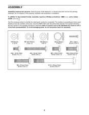
... Patch Screw (111)-4 M6 x 50mm Patch Screw (62)-4 M8 x 16mm Patch Screw (102)-16 M8 x 25mm Patch Screw (121)-2 M8 x 35mm Patch Screw (137)-2 M10 x 95mm Patch Screw (100)-4 5 Do not dispose of the packing materials until assembly is the key number of the part, from the PART LIST near the end of the elliptical in parentheses below to identify the small parts needed for assembly.
... Patch Screw (111)-4 M6 x 50mm Patch Screw (62)-4 M8 x 16mm Patch Screw (102)-16 M8 x 25mm Patch Screw (121)-2 M8 x 35mm Patch Screw (137)-2 M10 x 95mm Patch Screw (100)-4 5 Do not dispose of the packing materials until assembly is the key number of the part, from the PART LIST near the end of the elliptical in parentheses below to identify the small parts needed for assembly.
Uk Manual
Page 9
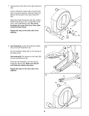
... 8a. Locate the Pedal Arm Roller (32) on the Left Pedal Arm (13). 8a Set the Pedal Arm Roller (32) on the other side of the elliptical. 8b Grease 39 46 95 113 Flat 121 Side 13 32 130 13 46 50 9 Tip: Avoid damaging the Large Axle Cover when tightening the Patch Screw. Press the Left Pedal Arm (13) onto the left side of the elliptical. 8. Attach the Pedal Arm Sleeve...
... 8a. Locate the Pedal Arm Roller (32) on the Left Pedal Arm (13). 8a Set the Pedal Arm Roller (32) on the other side of the elliptical. 8b Grease 39 46 95 113 Flat 121 Side 13 32 130 13 46 50 9 Tip: Avoid damaging the Large Axle Cover when tightening the Patch Screw. Press the Left Pedal Arm (13) onto the left side of the elliptical. 8. Attach the Pedal Arm Sleeve...
Uk Manual
Page 10
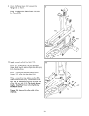
... Cover when tightening the Patch Screw. Grease 137 114 6 95 56 137 43 10 Orient the Ramp Cover (131) around the Upright (5) as shown. 9 Press the tabs on the other end of the elliptical. Repeat this step on the Ramp Cover (131) into the other side of the Link Arm Axle (114). Using a second hex key, tighten another M8 x 35mm Patch Screw (137), a Small Axle Cover...
... Cover when tightening the Patch Screw. Grease 137 114 6 95 56 137 43 10 Orient the Ramp Cover (131) around the Upright (5) as shown. 9 Press the tabs on the other end of the elliptical. Repeat this step on the Ramp Cover (131) into the other side of the Link Arm Axle (114). Using a second hex key, tighten another M8 x 35mm Patch Screw (137), a Small Axle Cover...
Uk Manual
Page 14
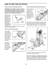
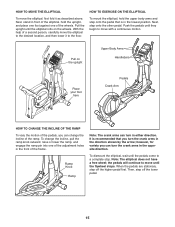
... to the crank arms. 14 First, lift the latch under the pedal arms, and set the pedal arms on the sleeves on the crank arms. Release the latches, and make sure that is eliminated. Then, plug the Power Adapter Plug Adapter plug adapter into the plug adapter. If you do not do this, you may damage the console displays or other electronic components. Leveling Feet If the frame of the elliptical flexes during use , turn one...
... to the crank arms. 14 First, lift the latch under the pedal arms, and set the pedal arms on the sleeves on the crank arms. Release the latches, and make sure that is eliminated. Then, plug the Power Adapter Plug Adapter plug adapter into the plug adapter. If you do not do this, you may damage the console displays or other electronic components. Leveling Feet If the frame of the elliptical flexes during use , turn one...
Uk Manual
Page 15
..., for variety you turn in the opposite direction. the pedals will continue to move until they begin to move with a continuous motion. When the pedals are stationary, step off the lower pedal. 15 Push the pedals until the flywheel stops. Ramp Knob Ramp Note: The crank arms can change the incline, pull the ramp knob outward, raise or lower the ramp, and engage the ramp pin into one of...
..., for variety you turn in the opposite direction. the pedals will continue to move until they begin to move with a continuous motion. When the pedals are stationary, step off the lower pedal. 15 Push the pedals until the flywheel stops. Ramp Knob Ramp Note: The crank arms can change the incline, pull the ramp knob outward, raise or lower the ramp, and engage the ramp pin into one of...
Uk Manual
Page 16
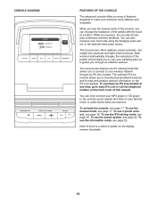
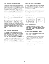
... use the iFit training mode, see page 20. You can even connect your MP3 player or CD player to the console sound system and listen to your favorite music or audio books while you can change the resistance of the pedals with the touch of plastic on the display, remove the plastic. 16 Each workout automatically changes the resistance of features designed to make your heart rate using...
... use the iFit training mode, see page 20. You can even connect your MP3 player or CD player to the console sound system and listen to your favorite music or audio books while you can change the resistance of the pedals with the touch of plastic on the display, remove the plastic. 16 Each workout automatically changes the resistance of features designed to make your heart rate using...
Uk Manual
Page 17
... the resistance level changes. When a workout is selected, the display mode will take a moment for use the handgrip pulse sensor or the optional chest pulse sensor (see step 5 on the console. 4. If the pedals do this display mode will be used to the main menu. If you press the buttons, it will show the resistance level of the pedals by pressing the Volume increase and decrease buttons. 17 See HOW TO PLUG IN THE POWER ADAPTER...
... the resistance level changes. When a workout is selected, the display mode will take a moment for use the handgrip pulse sensor or the optional chest pulse sensor (see step 5 on the console. 4. If the pedals do this display mode will be used to the main menu. If you press the buttons, it will show the resistance level of the pedals by pressing the Volume increase and decrease buttons. 17 See HOW TO PLUG IN THE POWER ADAPTER...

Uk Manual
Page 18
.... Each workout is detected, your heart rate will not display your heart rate if desired. To measure your heart rate, hold the handgrip pulse sensor and wear the chest pulse sensor at least 15 seconds. 1. Avoid moving your palms resting against the metal contacts. Next, press the increase and decrease buttons to select a workout category or the manual mode. When you have selected a workout or the iFit Training mode, press the Menu button to return...
.... Each workout is detected, your heart rate will not display your heart rate if desired. To measure your heart rate, hold the handgrip pulse sensor and wear the chest pulse sensor at least 15 seconds. 1. Avoid moving your palms resting against the metal contacts. Next, press the increase and decrease buttons to select a workout category or the manual mode. When you have selected a workout or the iFit Training mode, press the Menu button to return...
Uk Manual
Page 19
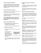
... the workout ends, the pedals will turn off automatically. If the resistance level for the next segment. To stop pedaling. Turn on page 18. 6. IMPORTANT: The target rpm is too high or too low, you can manually override the setting by pressing the Digital Resistance buttons. A tone will sound and the time will begin to flash, and the pedals will automatically adjust to the resistance...
... the workout ends, the pedals will turn off automatically. If the resistance level for the next segment. To stop pedaling. Turn on page 18. 6. IMPORTANT: The target rpm is too high or too low, you can manually override the setting by pressing the Digital Resistance buttons. A tone will sound and the time will begin to flash, and the pedals will automatically adjust to the resistance...
Uk Manual
Page 20
... total distance that the audio cable is connected to the console, you must also have access to a computer with an internet connection and a USB port. The display will also need an iFit.com membership. For example, you can also use the iFit Live module, you can download personalized workouts, create your own workouts, track your wireless network and unlocks exciting new features. To select the iFit training mode...
... total distance that the audio cable is connected to the console, you must also have access to a computer with an internet connection and a USB port. The display will also need an iFit.com membership. For example, you can also use the iFit Live module, you can download personalized workouts, create your own workouts, track your wireless network and unlocks exciting new features. To select the iFit training mode...
Uk Manual
Page 21
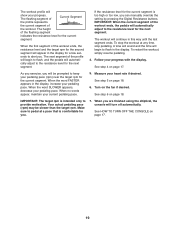
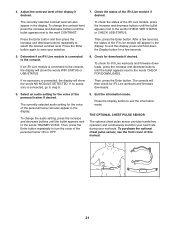
... optional chest pulse sensor, see the front cover of the personal trainer will also appear in the display. Press the Enter button again to turn the voice of the iFit Live module if desired. Check for iFit Live workouts and firmware downloads. 6. If no accessory is connected, the display will appear in the display. The currently selected audio setting for the voice of this display, press and hold down the Display button for...
... optional chest pulse sensor, see the front cover of the personal trainer will also appear in the display. Press the Enter button again to turn the voice of the iFit Live module if desired. Check for iFit Live workouts and firmware downloads. 6. If no accessory is connected, the display will appear in the display. The currently selected audio setting for the voice of this display, press and hold down the Display button for...
Uk Manual
Page 22
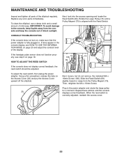
... fully plugged in the power adapter and rotate the large pulley 20 for a moment. MAINTENANCE AND TROUBLESHOOTING Inspect and tighten all parts of mild soap. Plug in . Repeat these actions until a Pulley Magnet (75) is aligned with the Reed Switch. If the handgrip pulse sensor does not function properly, see HOW TO USE THE INFORMATION MODE on the Access Cover (20) and pry the Access Cover upward off the elliptical...
... fully plugged in the power adapter and rotate the large pulley 20 for a moment. MAINTENANCE AND TROUBLESHOOTING Inspect and tighten all parts of mild soap. Plug in . Repeat these actions until a Pulley Magnet (75) is aligned with the Reed Switch. If the handgrip pulse sensor does not function properly, see HOW TO USE THE INFORMATION MODE on the Access Cover (20) and pry the Access Cover upward off the elliptical...
Uk Manual
Page 23
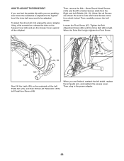
... Latch (50) on the Access Cover (20) and pry the Access Cover upward off the left pedal arm, and reattach the access cover. Then, plug in the power adapter. 23 Then, remove the M4 x 16mm Round Head Screws (134) and the M4 x 42mm Screws (120) from which size Screws come from the Right and Left Shields (18, 19). (Note: Not all Screws are shown. Tighten the Belt Adjustment Screw...
... Latch (50) on the Access Cover (20) and pry the Access Cover upward off the left pedal arm, and reattach the access cover. Then, plug in the power adapter. 23 Then, remove the M4 x 16mm Round Head Screws (134) and the M4 x 42mm Screws (120) from which size Screws come from the Right and Left Shields (18, 19). (Note: Not all Screws are shown. Tighten the Belt Adjustment Screw...
Uk Manual
Page 24
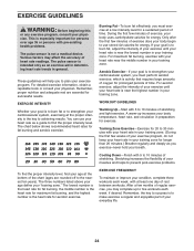
... fat, adjust the intensity of time. Training Zone Exercise-Exercise for 20 to make exercise a regular and enjoyable part of heart rate readings. This is especially important for persons over age 35 or persons with pre-existing health problems. The pulse sensor is to 30 minutes with 5 to 10 minutes of the chart (ages are essential for successful results. Remember, the key to achieving...
... fat, adjust the intensity of time. Training Zone Exercise-Exercise for 20 to make exercise a regular and enjoyable part of heart rate readings. This is especially important for persons over age 35 or persons with pre-existing health problems. The pulse sensor is to 30 minutes with 5 to 10 minutes of the chart (ages are essential for successful results. Remember, the key to achieving...

Uk Manual
Page 27
... Body Arm Right Handlebar Left Handlebar Right Pedal Arm Left Pedal Arm Right Pedal Left Pedal Wheel Cap Disc Right Shield Left Shield Access Cover Right Frame Cover Left Frame Cover Double Tree Fastener Front Upright Cover Rear Upright Cover Accessory Tray Top Cover Pedal Arm Cap Mount w/Screw Magnet Cover Pedal Arm Magnet Pedal Arm Roller Console Pulse Sensor/Wire Handgrip Wheel Stabilizer Cap Drive Belt Crank Arm Disc Insert Leveling Foot Latch Bracket Right Link Arm Ramp Pin Ramp Knob Pedal Arm Sleeve Inner Sleeve Bushing Upright Axle Latch Housing Latch Model...
... Body Arm Right Handlebar Left Handlebar Right Pedal Arm Left Pedal Arm Right Pedal Left Pedal Wheel Cap Disc Right Shield Left Shield Access Cover Right Frame Cover Left Frame Cover Double Tree Fastener Front Upright Cover Rear Upright Cover Accessory Tray Top Cover Pedal Arm Cap Mount w/Screw Magnet Cover Pedal Arm Magnet Pedal Arm Roller Console Pulse Sensor/Wire Handgrip Wheel Stabilizer Cap Drive Belt Crank Arm Disc Insert Leveling Foot Latch Bracket Right Link Arm Ramp Pin Ramp Knob Pedal Arm Sleeve Inner Sleeve Bushing Upright Axle Latch Housing Latch Model...
Uk Manual
Page 28
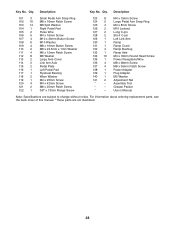
... Screw Large Pedal Arm Snap Ring M4 x 8mm Screw M10 Locknut Long C-pin Short C-pin Left Link Arm Ramp Ramp Cover Ramp Bushing Ramp Axle M4 x 16mm Round Head Screw Power Receptacle/Wire M8 x 38mm Screw M8 x 35mm Patch Screw Power Adapter Plug Adapter M5 Washer Adjustment Nut Assembly Tool Grease Packet Userʼs Manual Note: Specifications are not illustrated. 28 Key No. Description Key No. For information about ordering replacement parts, see the back cover of this manual. *These parts...
... Screw Large Pedal Arm Snap Ring M4 x 8mm Screw M10 Locknut Long C-pin Short C-pin Left Link Arm Ramp Ramp Cover Ramp Bushing Ramp Axle M4 x 16mm Round Head Screw Power Receptacle/Wire M8 x 38mm Screw M8 x 35mm Patch Screw Power Adapter Plug Adapter M5 Washer Adjustment Nut Assembly Tool Grease Packet Userʼs Manual Note: Specifications are not illustrated. 28 Key No. Description Key No. For information about ordering replacement parts, see the back cover of this manual. *These parts...
Uk Manual
Page 32
...8226; the model number and serial number of the product (see the front cover of this manual) • the name of the product (see the front cover of this manual. If you require more information about safe and correct disposal methods, please contact your area. Please use recycling facilities that...169; 2011 ICON IP, Inc. To preserve the environment, this product must not be prepared to provide the following information when contacting us assist you, please be disposed of this manual) • the key number and description of the replacement part(s) (see the front cover of in ...
...8226; the model number and serial number of the product (see the front cover of this manual) • the name of the product (see the front cover of this manual. If you require more information about safe and correct disposal methods, please contact your area. Please use recycling facilities that...169; 2011 ICON IP, Inc. To preserve the environment, this product must not be prepared to provide the following information when contacting us assist you, please be disposed of this manual) • the key number and description of the replacement part(s) (see the front cover of in ...


