
GS748TR Hardware manual
Page 13
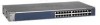
... the NETGEAR GS724TR Smart Switch front panel: System LEDs Port LEDs Figure 2-1 10/100/1000M Ethernet Ports SFP Ports The front panel contains the following: • 24 RJ-45 connectors for 10/100/1000Mbps auto sensing Gigabit Ethernet switching ports. • Two SFP slots for SFP modules supporting 1000(1000Base-SX/LX)/100M SFP. • Reset button...
... the NETGEAR GS724TR Smart Switch front panel: System LEDs Port LEDs Figure 2-1 10/100/1000M Ethernet Ports SFP Ports The front panel contains the following: • 24 RJ-45 connectors for 10/100/1000Mbps auto sensing Gigabit Ethernet switching ports. • Two SFP slots for SFP modules supporting 1000(1000Base-SX/LX)/100M SFP. • Reset button...

GS748TR Hardware manual
Page 14
... Reset button to restart the device. • Recessed default reset button to restore the device back to the factory defaults. • Port LEDs 2-6 Physical Description v1.0, December 2007 GS700TR Series Hardware Installation Guide • System LEDs Figure 2-2 illustrates the NETGEAR GS724TR Smart Switch back... panel: Figure 2-2 RS-232 Power Connector The back panel contains the following : • 48 RJ-45 connectors for 10/100/1000Mbps auto sensing Gigabit Ethernet switching ports. • Four SFP slots for...
... Reset button to restart the device. • Recessed default reset button to restore the device back to the factory defaults. • Port LEDs 2-6 Physical Description v1.0, December 2007 GS700TR Series Hardware Installation Guide • System LEDs Figure 2-2 illustrates the NETGEAR GS724TR Smart Switch back... panel: Figure 2-2 RS-232 Power Connector The back panel contains the following : • 48 RJ-45 connectors for 10/100/1000Mbps auto sensing Gigabit Ethernet switching ports. • Four SFP slots for...

GS748TR Hardware manual
Page 28
... your product. ACT LED is flashing continuously on all connectors are outside of the network. Break the loop by resetting the switch. Configuration If problems occur after altering the network configuration, restore the original connections and determine the problem by implementing the...Ensure the network adapter cards installed in the required ports. In North America, call 1-888-NETGEAR. To reset the switch, remove the AC power from any other physical aspects of the switch by ensuring that there is correct. A network loop (redundant path) has been created....
... your product. ACT LED is flashing continuously on all connectors are outside of the network. Break the loop by resetting the switch. Configuration If problems occur after altering the network configuration, restore the original connections and determine the problem by implementing the...Ensure the network adapter cards installed in the required ports. In North America, call 1-888-NETGEAR. To reset the switch, remove the AC power from any other physical aspects of the switch by ensuring that there is correct. A network loop (redundant path) has been created....

GS748TR Hardware manual
Page 35
...2-6 100BASE-TX 1-2 10BASE-T 1-2 1U 1-3 8-pin 2-8 A AC Power 2-6, 2-7 AGM731F 2-9 AGM732F 2-9 AGM733 2-9 Applying AC Power 4-17 Attaching Switch to a Rack 4-15 Auto Sensing 1-2 Auto Uplink 2-8, 2-9 Auto-negotiating 1-2 Auto-sensing 2-8 B Back-pressure 1-3 Brackets 4-14 C Category 5 ...Switch 4-16 Copper 1-1 Crossover 2-8 D Default IP Address 4-18 Default Reset Button 2-5, 2-6 Device Hardware Interfaces 2-8 Duplex Mode 2-8 E Example of Desktop Switching 3-11 F Factory Default Button 2-9 Factory Defaults 2-5 Fan LED 2-8 Fiber Connectivity 1-1 Flat Surface 4-14 Full-duplex 1-2 G GBIC 1-2, 2-9 Gigabit...
...2-6 100BASE-TX 1-2 10BASE-T 1-2 1U 1-3 8-pin 2-8 A AC Power 2-6, 2-7 AGM731F 2-9 AGM732F 2-9 AGM733 2-9 Applying AC Power 4-17 Attaching Switch to a Rack 4-15 Auto Sensing 1-2 Auto Uplink 2-8, 2-9 Auto-negotiating 1-2 Auto-sensing 2-8 B Back-pressure 1-3 Brackets 4-14 C Category 5 ...Switch 4-16 Copper 1-1 Crossover 2-8 D Default IP Address 4-18 Default Reset Button 2-5, 2-6 Device Hardware Interfaces 2-8 Duplex Mode 2-8 E Example of Desktop Switching 3-11 F Factory Default Button 2-9 Factory Defaults 2-5 Fan LED 2-8 Fiber Connectivity 1-1 Flat Surface 4-14 Full-duplex 1-2 G GBIC 1-2, 2-9 Gigabit...

GS748TR Hardware manual
Page 36
... IEEE 802.3z 1-2 IEEE Standards 1-2 IEEE-compliant 1-2 Installation Guide 1-4 Installing an SFP GBIC Module 4-16 Installing the Switch 4-14 L LED Designations 2-7 Link/ACT LED 2-7 Low Latency 1-2 M MAC 1-3 Media Access Control 1-3 Mounting Holes 4-14 N Nylon Washers 4-14 O ON/OFF...14 Rack-mount Kit 1-4, 4-14 Reset Button 2-5, 2-6 RJ-45 1-2 RJ-45 Ports 2-8 Rubber Footpad 4-14 Rubber footpads 1-4 S SFP GBIC Module 2-9 SFP Link/ACT LED 2-8 SFP Module Bay 4-17 Site Requirements 4-13 Small Form-factor Pluggable (SFP) 1-2 Smart Switch Resource CD 1-4 Smart Wizard Discovery 1-2 Straight-through 2-8 ...
... IEEE 802.3z 1-2 IEEE Standards 1-2 IEEE-compliant 1-2 Installation Guide 1-4 Installing an SFP GBIC Module 4-16 Installing the Switch 4-14 L LED Designations 2-7 Link/ACT LED 2-7 Low Latency 1-2 M MAC 1-3 Media Access Control 1-3 Mounting Holes 4-14 N Nylon Washers 4-14 O ON/OFF...14 Rack-mount Kit 1-4, 4-14 Reset Button 2-5, 2-6 RJ-45 1-2 RJ-45 Ports 2-8 Rubber Footpad 4-14 Rubber footpads 1-4 S SFP GBIC Module 2-9 SFP Link/ACT LED 2-8 SFP Module Bay 4-17 Site Requirements 4-13 Small Form-factor Pluggable (SFP) 1-2 Smart Switch Resource CD 1-4 Smart Wizard Discovery 1-2 Straight-through 2-8 ...


