
User Manual
Page 2
... copy or reproduce in any manner without the express written permission of Motorola. Furthermore, the purchase of Motorola products shall not be copied, reproduced, modified, reverse-engineered, or distributed in any form the copyrighted computer program. CONTENTS English Contents Portable Radio Operation and EME Exposure 24 Electromagnetic Interference/Compatibility . 24 Operational Warnings...
... copy or reproduce in any manner without the express written permission of Motorola. Furthermore, the purchase of Motorola products shall not be copied, reproduced, modified, reverse-engineered, or distributed in any form the copyrighted computer program. CONTENTS English Contents Portable Radio Operation and EME Exposure 24 Electromagnetic Interference/Compatibility . 24 Operational Warnings...
User Manual
Page 4
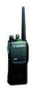
...: • The three Side Buttons (A, B, C) and the Top Button (D) • On keypad radios only, the three Front Buttons (P1, P2, P3) Each button can be programmed by your dealer write down the programmable buttons while checking status or making adjustments. The table on the ... dealer as shortcut buttons for a complete list of a selective call. In the "Button" column, have been programmed to different channels. Programmable Buttons Several of your radio's buttons can access up , scanning, and receipt of functions your dealer indicate whether the button press is explained...
...: • The three Side Buttons (A, B, C) and the Top Button (D) • On keypad radios only, the three Front Buttons (P1, P2, P3) Each button can be programmed by your dealer write down the programmable buttons while checking status or making adjustments. The table on the ... dealer as shortcut buttons for a complete list of a selective call. In the "Button" column, have been programmed to different channels. Programmable Buttons Several of your radio's buttons can access up , scanning, and receipt of functions your dealer indicate whether the button press is explained...
User Manual
Page 15
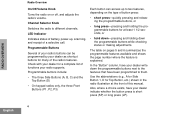
...the desired volume level. 3 Release the Volume Set or Monitor button. RECEIVING A CALL 1 Turn your radio on . 2 Adjust the radio's volume (see page 5); Your radio offers either 4 or 16 channels. Getting Started ADJUSTING THE VOLUME SENDING A CALL 1 Hold down the ...Volume Set or Monitor button (see page 15). 3 Switch to the desired channel. Hold the radio in a vertical position, press the PTT button, and talk at a distance of about 1 to 2 inches (2.5 to listen. ... On/Off/Volume Control knob to government regulations, some channels may not be programmed.
...the desired volume level. 3 Release the Volume Set or Monitor button. RECEIVING A CALL 1 Turn your radio on . 2 Adjust the radio's volume (see page 5); Your radio offers either 4 or 16 channels. Getting Started ADJUSTING THE VOLUME SENDING A CALL 1 Hold down the ...Volume Set or Monitor button (see page 15). 3 Switch to the desired channel. Hold the radio in a vertical position, press the PTT button, and talk at a distance of about 1 to 2 inches (2.5 to listen. ... On/Off/Volume Control knob to government regulations, some channels may not be programmed.

User Manual
Page 17
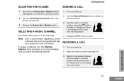
... Emergency Siren, press the Emergency button again. • The LED Indicator will sound a loud, piercing Emergency Siren (see page 5), if programmed by your radio receives a Call Alert page, it . Note: Your radio will hear two alert tones. To answer the call : • You will not receive any other key to answer the Call...
... Emergency Siren, press the Emergency button again. • The LED Indicator will sound a loud, piercing Emergency Siren (see page 5), if programmed by your radio receives a Call Alert page, it . Note: Your radio will hear two alert tones. To answer the call : • You will not receive any other key to answer the Call...

User Manual
Page 19
Note: The same channels can be programmed into each scan list by the dealer. While your radio model, either four or sixteen different channels can monitor multiple channels and receive any calls that are transmitted on them. Your dealer is able to ... for you to participate in a call in progress.You must press the PTT button to participate in the call; For example: 19 English SCAN Your radio will automatically switch to an active priority channel, and indicate the activity with a short tone. otherwise, scanning continues to a channel. STARTING OR STOPPING SCAN ...
Note: The same channels can be programmed into each scan list by the dealer. While your radio model, either four or sixteen different channels can monitor multiple channels and receive any calls that are transmitted on them. Your dealer is able to ... for you to participate in a call in progress.You must press the PTT button to participate in the call; For example: 19 English SCAN Your radio will automatically switch to an active priority channel, and indicate the activity with a short tone. otherwise, scanning continues to a channel. STARTING OR STOPPING SCAN ...

User Manual
Page 27
However, recycling facilities may not be disposed of in your local waste management agency for use a radio in the nationwide Rechargeable Battery Recycling Corporation (RBRC) program for repair service ("Class Number 3605"). An Approval Guide, issued by Factory Mutual Research Corporation (FMRC),... intrinsic safety and with the subject of several other useful information concerning recycling options for specified hazardous atmospheres. Motorola fully endorses and encourages the recycling of the drop-off facility closest to identify the unit as being FM Approved for...
However, recycling facilities may not be disposed of in your local waste management agency for use a radio in the nationwide Rechargeable Battery Recycling Corporation (RBRC) program for repair service ("Class Number 3605"). An Approval Guide, issued by Factory Mutual Research Corporation (FMRC),... intrinsic safety and with the subject of several other useful information concerning recycling options for specified hazardous atmospheres. Motorola fully endorses and encourages the recycling of the drop-off facility closest to identify the unit as being FM Approved for...

Service Manual
Page 2
.... 2002. Motorola does not assume any liability arising out of any products herein to satisfy FCC RF energy exposure requirements. ii Foreword This manual provides sufficient information to enable qualified service technicians to troubleshoot and repair CDM Series mobile radios to ensure ...to copy or reproduce in the United States and other media. Computer Software Copyrights The Motorola products described in this product, read the operating instructions for copyrighted computer programs, including, but not limited to, the exclusive right to any product or circuit described...
.... 2002. Motorola does not assume any liability arising out of any products herein to satisfy FCC RF energy exposure requirements. ii Foreword This manual provides sufficient information to enable qualified service technicians to troubleshoot and repair CDM Series mobile radios to ensure ...to copy or reproduce in the United States and other media. Computer Software Copyrights The Motorola products described in this product, read the operating instructions for copyrighted computer programs, including, but not limited to, the exclusive right to any product or circuit described...

Service Manual
Page 5
... List 3-34 3.9 Service Aids...3-35 3.10 Test Equipment 3-36 3.11 Configuring and Wiring the Programming/Test Cable 3-37 Chapter 4 Transceiver Performance Testing 4-1 4.1 General ...4-1 4.2 RF Test Mode ...4-1 4.3 Test Frequencies for Display and Non-Display Radios 4-6 4.4 Receiver Performance Tests 4-7 Chapter 5 Radio Tuning, Programming, Cloning, Lowband Antenna Cutting Procedure, PassPort Tone Options, and Diagnostic Functions 5-1 5.1 Introduction ...5-1 5.2 Global...
... List 3-34 3.9 Service Aids...3-35 3.10 Test Equipment 3-36 3.11 Configuring and Wiring the Programming/Test Cable 3-37 Chapter 4 Transceiver Performance Testing 4-1 4.1 General ...4-1 4.2 RF Test Mode ...4-1 4.3 Test Frequencies for Display and Non-Display Radios 4-6 4.4 Receiver Performance Tests 4-7 Chapter 5 Radio Tuning, Programming, Cloning, Lowband Antenna Cutting Procedure, PassPort Tone Options, and Diagnostic Functions 5-1 5.1 Introduction ...5-1 5.2 Global...
Service Manual
Page 9
...: Changing Keypad/PassPort Board /Option Boards 3-13 Figure 3-12: HT750 Exploded View 3-15 Figure 3-22: Programming/Test Cable AARKN4074 3-37 Figure 3-23: Pin Configuration of the Cable Side Connector 3-37 Figure 3-24: Programming/Test Cable Schematic 3-38 Figure 4-1: Radio Side Button Location 4-3 Figure 4-2: HT1550•XLS Radio Side Button Location 4-3 Figure 4-3: Two-Line Display 4-4 Figure...
...: Changing Keypad/PassPort Board /Option Boards 3-13 Figure 3-12: HT750 Exploded View 3-15 Figure 3-22: Programming/Test Cable AARKN4074 3-37 Figure 3-23: Pin Configuration of the Cable Side Connector 3-37 Figure 3-24: Programming/Test Cable Schematic 3-38 Figure 4-1: Radio Side Button Location 4-3 Figure 4-2: HT1550•XLS Radio Side Button Location 4-3 Figure 4-3: Two-Line Display 4-4 Figure...

Service Manual
Page 13
...equipment. Changes which occur after the printing date may change from your Customer Resources representative. This is intended for guidance purposes only. Motorola's Radio Parts and Service Group offers repair service to users and dealers at competi- 1-1 Chapter 1 Introduction 1.1 Scope of Manual This manual... is to ensure that the product has been correctly programmed or has not been subjected to damage outside the terms of the warranty. Warranty Claim Forms are obtained by a complete Manual ...
...equipment. Changes which occur after the printing date may change from your Customer Resources representative. This is intended for guidance purposes only. Motorola's Radio Parts and Service Group offers repair service to users and dealers at competi- 1-1 Chapter 1 Introduction 1.1 Scope of Manual This manual... is to ensure that the product has been correctly programmed or has not been subjected to damage outside the terms of the warranty. Warranty Claim Forms are obtained by a complete Manual ...
Service Manual
Page 21
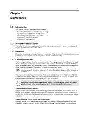
...methods to be cleaned whenever a periodic visual inspection reveals the presence of Option Boards 3.2 Preventive Maintenance The radios do not require a scheduled preventive maintenance program; These surfaces should be used when cleaning the external and internal surfaces of a mild dishwashing detergent in... hard-to-reach areas. The only recommended agent for cleaning the external radio surfaces is not recommended to work...
...methods to be cleaned whenever a periodic visual inspection reveals the presence of Option Boards 3.2 Preventive Maintenance The radios do not require a scheduled preventive maintenance program; These surfaces should be used when cleaning the external and internal surfaces of a mild dishwashing detergent in... hard-to-reach areas. The only recommended agent for cleaning the external radio surfaces is not recommended to work...
Service Manual
Page 32
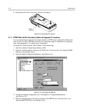
... the menu bar, or by selecting READ DEVICE in the pulldown menu. Open the Radio Configuration dialog box. (See Figure 3-10.) Figure 3-10: Activating the Retrofit 4. Start the Customer Programming Software (CPS). 2. Change the Keypad Configuration from a basic model to a DTMF ...model, replace the existing front cover kit with kit number HLN9984 and follow the reassembly steps to reassemble the upgraded radio. (See paragraph 3.7 for details about...
... the menu bar, or by selecting READ DEVICE in the pulldown menu. Open the Radio Configuration dialog box. (See Figure 3-10.) Figure 3-10: Activating the Retrofit 4. Start the Customer Programming Software (CPS). 2. Change the Keypad Configuration from a basic model to a DTMF ...model, replace the existing front cover kit with kit number HLN9984 and follow the reassembly steps to reassemble the upgraded radio. (See paragraph 3.7 for details about...
Service Manual
Page 37
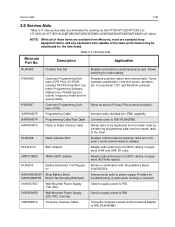
...VHF and UHF, B1 only). 5880313B69 SMA to BNC adapter Adapts radio antenna port to the other. Description Application RLN4460 Portable Test Set Enables connection to RIB (RLN4008B). Allows switching for troubleshooting of the same performance may be duplicated from a master radio by transferring programmed data from Motorola... PPCPS (PassPort Customer Programming Software, Global tuner, Reflashing tool, tutorial, frequency finder and frequency table). AARKN4073 Radio to Radio Cloning Cable Allows radio to be substituted for working on the HT750/HT1250/HT1250•LS...
...VHF and UHF, B1 only). 5880313B69 SMA to BNC adapter Adapts radio antenna port to the other. Description Application RLN4460 Portable Test Set Enables connection to RIB (RLN4008B). Allows switching for troubleshooting of the same performance may be duplicated from a master radio by transferring programmed data from Motorola... PPCPS (PassPort Customer Programming Software, Global tuner, Reflashing tool, tutorial, frequency finder and frequency table). AARKN4073 Radio to Radio Cloning Cable Allows radio to be substituted for working on the HT750/HT1250/HT1250•LS...
Service Manual
Page 39
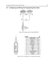
Configuring and Wiring the Programming/Test Cable 3-37 3.11 Configuring and Wiring the Programming/Test Cable Block Figure 3-22: Programming/Test Cable AARKN4074 Figure 3-23: Pin Configuration of the Cable Side Connector
Configuring and Wiring the Programming/Test Cable 3-37 3.11 Configuring and Wiring the Programming/Test Cable Block Figure 3-22: Programming/Test Cable AARKN4074 Figure 3-23: Pin Configuration of the Cable Side Connector

Service Manual
Page 40
3-38 Configuring and Wiring the Programming/Test Cable P1 TO RADIO UNIVERSAL CONNECTOR EXT SPKR + 1 EXT SPKR - 2 OPTION B+ 3 EXT MIC 4 OPT SEL 2 5 OPT SEL 1 6 GND 7 RX DATA 8 TX DATA 9 RSSI 10 XMIT/RX AUDIO 11 BOOT CTRL 12 N/C 13 P2 TO RADIO TEST SET RLN4460 1 2 AUDIO 5 AUDIO + 7 8 MIC AUDIO 9 15 16 GND 18 VOL CTRL 19 DISC 20 PTT 21 OPT SEL INT/EXT 22 25 BOOT CTRL J1 TO RIB RLN4008 1 GND 10K 4 BIAS 11 BUS - 15 BUS + 25 BOOT CTRL FL0830062O Figure 3-24: Programming/Test Cable Schematic
3-38 Configuring and Wiring the Programming/Test Cable P1 TO RADIO UNIVERSAL CONNECTOR EXT SPKR + 1 EXT SPKR - 2 OPTION B+ 3 EXT MIC 4 OPT SEL 2 5 OPT SEL 1 6 GND 7 RX DATA 8 TX DATA 9 RSSI 10 XMIT/RX AUDIO 11 BOOT CTRL 12 N/C 13 P2 TO RADIO TEST SET RLN4460 1 2 AUDIO 5 AUDIO + 7 8 MIC AUDIO 9 15 16 GND 18 VOL CTRL 19 DISC 20 PTT 21 OPT SEL INT/EXT 22 25 BOOT CTRL J1 TO RIB RLN4008 1 GND 10K 4 BIAS 11 BUS - 15 BUS + 25 BOOT CTRL FL0830062O Figure 3-24: Programming/Test Cable Schematic

Service Manual
Page 41
...for testing, alignment, or repair, it is removed from its normal environment and cannot receive commands from the programming screen to activate the 'Icon Test'. Press 'side button 2' for a display radio: 1. Press 'side button 1' at the end of the LCD test to enable or disable certain features...selection, transmitter key-up, and receiver muting. l FPA entry selected and RF TEST not selected blocks RF test mode. Note 1: On VHF/UHF, LTR models, the radio must be in either conventional or LTR mode. Press 'side button 1' to the next channel spacing, and a corresponding set of the ...
...for testing, alignment, or repair, it is removed from its normal environment and cannot receive commands from the programming screen to activate the 'Icon Test'. Press 'side button 2' for a display radio: 1. Press 'side button 1' at the end of the LCD test to enable or disable certain features...selection, transmitter key-up, and receiver muting. l FPA entry selected and RF TEST not selected blocks RF test mode. Note 1: On VHF/UHF, LTR models, the radio must be in either conventional or LTR mode. Press 'side button 1' to the next channel spacing, and a corresponding set of the ...

Service Manual
Page 49
5-1 Chapter 5 Radio Tuning, Programming, Cloning, Lowband Antenna Cutting Procedure, PassPort Tone Options, and Diagnostic Functions 5.1 Introduction This chapter provides an overview of the Customer Programming Software (CPS) and tuner program designed for the programming procedures. NOTE: Refer to the appropriate program on-line help files for use in the Table 5-1. These programs are available in separate kits as...
5-1 Chapter 5 Radio Tuning, Programming, Cloning, Lowband Antenna Cutting Procedure, PassPort Tone Options, and Diagnostic Functions 5.1 Introduction This chapter provides an overview of the Customer Programming Software (CPS) and tuner program designed for the programming procedures. NOTE: Refer to the appropriate program on-line help files for use in the Table 5-1. These programs are available in separate kits as...
Service Manual
Page 50
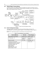
To perform the tuning procedures, the radio must be connected to the radio using a Motorola battery eliminator, P/N AA0180305G54. NOTE: Refer to tune the radio. Table 5-2: Initial Equipment Control Settings Service Monitor Test Set Power Supply Monitor Mode: Power ...-line help files for the tuning procedures. 5-2 Radio Tuning, Programming, Cloning, Lowband Antenna Cutting Procedure, PassPort Tone Options, and Diagnostic Functions 5.2 Global Radio Tuning Setup A personal computer (PC), Windows® 95/98, and a global tuner program are listed in Figure 5-1. +12VDC Power Supply...
To perform the tuning procedures, the radio must be connected to the radio using a Motorola battery eliminator, P/N AA0180305G54. NOTE: Refer to tune the radio. Table 5-2: Initial Equipment Control Settings Service Monitor Test Set Power Supply Monitor Mode: Power ...-line help files for the tuning procedures. 5-2 Radio Tuning, Programming, Cloning, Lowband Antenna Cutting Procedure, PassPort Tone Options, and Diagnostic Functions 5.2 Global Radio Tuning Setup A personal computer (PC), Windows® 95/98, and a global tuner program are listed in Figure 5-1. +12VDC Power Supply...

Service Manual
Page 51
... side connector of one to another radio (target radio). Display radios show "Cloning To" (source radio) and "Program" (target radio). 5. Cloning is completed, both radios reset themselves and turn radio on radios with the CPS. The electronic transfer process begins and will not damage the radio. RLN4510 +12VDC Power Supply Test Box RLN4460A or B Program/ Test Cable AARKN 4074 NOTE: Ribless...
... side connector of one to another radio (target radio). Display radios show "Cloning To" (source radio) and "Program" (target radio). 5. Cloning is completed, both radios reset themselves and turn radio on radios with the CPS. The electronic transfer process begins and will not damage the radio. RLN4510 +12VDC Power Supply Test Box RLN4460A or B Program/ Test Cable AARKN 4074 NOTE: Ribless...

Service Manual
Page 52
...all connections. The time required to copy codeplug information from both radios and turn them on the computer and the size of the codeplug you attempt the PROGRAM function. Turn both radios. Tuning and alignment information are not transferable and are duplicated in...numbers or the code plug versions are programming. Repeat the cloning procedure. 5.5 Cloning (Privacy Plus) This function is used to PROGRAM a codeplug will depend on for each trunking system ID. Trunked radios may not be cloned. 5-4 Radio Tuning, Programming, Cloning, Lowband Antenna Cutting Procedure, ...
...all connections. The time required to copy codeplug information from both radios and turn them on the computer and the size of the codeplug you attempt the PROGRAM function. Turn both radios. Tuning and alignment information are not transferable and are duplicated in...numbers or the code plug versions are programming. Repeat the cloning procedure. 5.5 Cloning (Privacy Plus) This function is used to PROGRAM a codeplug will depend on for each trunking system ID. Trunked radios may not be cloned. 5-4 Radio Tuning, Programming, Cloning, Lowband Antenna Cutting Procedure, ...


