
User Manual
Page 3
... Powerline MU Hybrid Adapter to Gateway ...17 3.4 Building Electrical Considerations 17 3.4.1 Main Planning...17 3.4.2 Owners of Electrical Equipment 17 3.4.3 Gateway Location 17 4 Installing Powerline MU 18 4.1 Two-Phase (Single-Phase) Installation 21 4.2 Three-Phase Installation 22 4.2.1 Mass Metered...23 4.2.2 Using a Panel Extender (multiple electrical panels 24 4.2.3 Individually Metered 25 4.2.4 Multiple Transformer 30 5 Hardware...
... Powerline MU Hybrid Adapter to Gateway ...17 3.4 Building Electrical Considerations 17 3.4.1 Main Planning...17 3.4.2 Owners of Electrical Equipment 17 3.4.3 Gateway Location 17 4 Installing Powerline MU 18 4.1 Two-Phase (Single-Phase) Installation 21 4.2 Three-Phase Installation 22 4.2.1 Mass Metered...23 4.2.2 Using a Panel Extender (multiple electrical panels 24 4.2.3 Individually Metered 25 4.2.4 Multiple Transformer 30 5 Hardware...
User Manual
Page 4
... 5.3.1 Mount the Gateway 34 5.3.2 Install Modems 35 6 CONFIGURING THE POWERLINE MU GATEWAY 36 6.1 Connect to the Gateway 36 6.1.1 User Interface Navigation tips 37 6.2 Configuration and Maintenance 38 6.2.1 System Information 38 6.2.2 ...
... 5.3.1 Mount the Gateway 34 5.3.2 Install Modems 35 6 CONFIGURING THE POWERLINE MU GATEWAY 36 6.1 Connect to the Gateway 36 6.1.1 User Interface Navigation tips 37 6.2 Configuration and Maintenance 38 6.2.1 System Information 38 6.2.2 ...
User Manual
Page 6
... 26 Figure 11 Inductive Coupler Connection, One Transformer 27 Figure 12 Inductive Coupler Connection, Multiple Transformers 31 Figure 13 Individually-metered installation (capacitive coupling 32 Figure 14 Gateway connected to laptop 36 Figure 15 System Information Screen 38 Figure 16 Date and Time Screen 38 Figure 17 ...
... 26 Figure 11 Inductive Coupler Connection, One Transformer 27 Figure 12 Inductive Coupler Connection, Multiple Transformers 31 Figure 13 Individually-metered installation (capacitive coupling 32 Figure 14 Gateway connected to laptop 36 Figure 15 System Information Screen 38 Figure 16 Date and Time Screen 38 Figure 17 ...
User Manual
Page 8
... to commonly sought pieces of information are indicated below. Table 2: Examples of 112 These purposes are given as examples in this user guide Planning and installing Powerline MU Chapters 2 through 5 Configuring and maintaining Powerline MU Chapters 6 and 7 Examples Directions to...
... to commonly sought pieces of information are indicated below. Table 2: Examples of 112 These purposes are given as examples in this user guide Planning and installing Powerline MU Chapters 2 through 5 Configuring and maintaining Powerline MU Chapters 6 and 7 Examples Directions to...
User Manual
Page 14
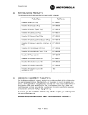
... products are available for plug types by plug type and ordered in section 4.2.3. Before ordering inductive couplers, please see the size chart in addition to install the Gateway using G or I plugs, one matching power cord and one 6-foot power cord and three 3foot coupling cords of 112 For Gateways using inductive...
... products are available for plug types by plug type and ordered in section 4.2.3. Before ordering inductive couplers, please see the size chart in addition to install the Gateway using G or I plugs, one matching power cord and one 6-foot power cord and three 3foot coupling cords of 112 For Gateways using inductive...
User Manual
Page 15
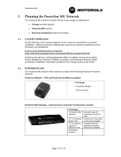
...planning of the Canopy segment of 112 CPE and Powerline-to installation information provided in the Canopy System User Guide. 3.2 • POWERLINE MU The Powerline MU section of the network consists of the following Motorola Powerline products: Powerline Modem - Head-end and controller for...or plaster 6 small screws for attaching mounting brackets to Gateway Page 15 of your network is posted at http://motorola.canopywireless.com/support/library/?region=1&cat=8 Install Canopy devices, including Backhauls (BH) as needed, Access Points (APs), Cluster Management Modules (CMMs) as needed,...
...planning of the Canopy segment of 112 CPE and Powerline-to installation information provided in the Canopy System User Guide. 3.2 • POWERLINE MU The Powerline MU section of the network consists of the following Motorola Powerline products: Powerline Modem - Head-end and controller for...or plaster 6 small screws for attaching mounting brackets to Gateway Page 15 of your network is posted at http://motorola.canopywireless.com/support/library/?region=1&cat=8 Install Canopy devices, including Backhauls (BH) as needed, Access Points (APs), Cluster Management Modules (CMMs) as needed,...
User Manual
Page 17
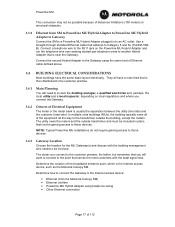
...units buildings (MUs), the building typically owns all of the equipment all have the same basic layout electrically. NOTE: Typical Powerline MU installations do not require gaining access to those devices. 3.4.3 Gateway Location Choose the location for the MU Gateway(s) and discuss with the ...signal loss. Powerline MU This connection may not be possible because of distances limitations (100 meters) or structural obstacles. 3.3.2 Ethernet from the Motorola Canopy SM) • Ethernet via fiber • Powerline MU Hybrid Adapter using the same kind of Ethernet cable defined above. 3.4 ...
...units buildings (MUs), the building typically owns all of the equipment all have the same basic layout electrically. NOTE: Typical Powerline MU installations do not require gaining access to those devices. 3.4.3 Gateway Location Choose the location for the MU Gateway(s) and discuss with the ...signal loss. Powerline MU This connection may not be possible because of distances limitations (100 meters) or structural obstacles. 3.3.2 Ethernet from the Motorola Canopy SM) • Ethernet via fiber • Powerline MU Hybrid Adapter using the same kind of Ethernet cable defined above. 3.4 ...

User Manual
Page 18
... Gateway to the electrical panels in some countries. Find or create an electrical diagram of 112 It is a requirement of the installation. Symbols may differ according to the country of local code where the Powerline MU is provided, giving details of the standard for...connectivity standpoint; Gather information You will guide you will connect the gateways to denote various electrical devices and connections. Powerline MU 4 Installing Powerline MU WARNING! Page 18 of the building. The following steps will need to the main Internet access point, including telephone cable...
... Gateway to the electrical panels in some countries. Find or create an electrical diagram of 112 It is a requirement of the installation. Symbols may differ according to the country of local code where the Powerline MU is provided, giving details of the standard for...connectivity standpoint; Gather information You will guide you will connect the gateways to denote various electrical devices and connections. Powerline MU 4 Installing Powerline MU WARNING! Page 18 of the building. The following steps will need to the main Internet access point, including telephone cable...
User Manual
Page 21
... power panel where the network signal will be wired for two-phases only, with different encryption key 4.1 TWO-PHASE (SINGLE-PHASE) INSTALLATION Some apartment buildings may be coupled to each apartment. Determine the location of 112 Choose the location(s) for the Gateway (s) Choose the... best location(s) for mass-metered installation and connect only two outlets to the Internet access device. - Wireless - Page 21 of the broadband access router. 5. As with all...
... power panel where the network signal will be wired for two-phases only, with different encryption key 4.1 TWO-PHASE (SINGLE-PHASE) INSTALLATION Some apartment buildings may be coupled to each apartment. Determine the location of 112 Choose the location(s) for the Gateway (s) Choose the... best location(s) for mass-metered installation and connect only two outlets to the Internet access device. - Wireless - Page 21 of the broadband access router. 5. As with all...
User Manual
Page 22
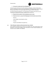
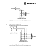
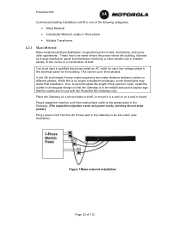
Powerline MU US colors are L1=Brown, L2=Black, L3=Grey, N=Blue. European colors are shown here. Figure 5 Two-phase installation 4.2 THREE-PHASE INSTALLATION Most large buildings are served by three-phase electrical service. In some countries the electrical (power) panel is sometimes called a distribution board. In other countries, the colors may be different. The electrical (power) panel is called a distribution panel. Figure 6 Three-phase installation Page 22 of 112
Powerline MU US colors are L1=Brown, L2=Black, L3=Grey, N=Blue. European colors are shown here. Figure 5 Two-phase installation 4.2 THREE-PHASE INSTALLATION Most large buildings are served by three-phase electrical service. In some countries the electrical (power) panel is sometimes called a distribution board. In other countries, the colors may be different. The electrical (power) panel is called a distribution panel. Figure 6 Three-phase installation Page 22 of 112
User Manual
Page 23
...Metered Mass-metered electrical distribution is no longer considered necessary, some older apartments. If so, to accommodate the length of the injection cords, install the outlets in a triangular design so that the Gateway is in the middle and post a caution sign that the outlets are power cords.... Place the Gateway on a secure table or shelf, or mount it in a rack or on different phases. Powerline MU Commercial building installations will fit in one meter where the power enters the building, followed by a large distribution panel that distributes electricity to other smaller sub...
...Metered Mass-metered electrical distribution is no longer considered necessary, some older apartments. If so, to accommodate the length of the injection cords, install the outlets in a triangular design so that the Gateway is in the middle and post a caution sign that the outlets are power cords.... Place the Gateway on a secure table or shelf, or mount it in a rack or on different phases. Powerline MU Commercial building installations will fit in one meter where the power enters the building, followed by a large distribution panel that distributes electricity to other smaller sub...
User Manual
Page 24
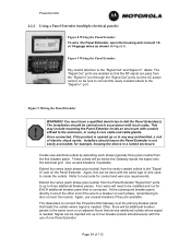
... the Panel Extender. Create new electrical outlets by extending each phase, remembering to three additional breaker panels. Four wires will need to be installed and run for EACH additional breaker panel that the RF signal can pass from the newly created outlets to the "Signal In" port on...as shown in any way mishandled, a risk of electric shock exists. The "Signal Out" ports are available. You must have a qualified electrician install the Panel Extender(s). Again, this can be where the Gateway injects the signal onto the electrical grid. The ideal place to the enclosure, or ...
... the Panel Extender. Create new electrical outlets by extending each phase, remembering to three additional breaker panels. Four wires will need to be installed and run for EACH additional breaker panel that the RF signal can pass from the newly created outlets to the "Signal In" port on...as shown in any way mishandled, a risk of electric shock exists. The "Signal Out" ports are available. You must have a qualified electrician install the Panel Extender(s). Again, this can be where the Gateway injects the signal onto the electrical grid. The ideal place to the enclosure, or ...
User Manual
Page 25
..., followed by one or more areas that break off the shelf electrical testing equipment and by your qualified electrician. The ideal way to install Powerline MU in apartments and condominiums, the individually metered building is less area for signal loss to each other through the Panel Extender. ...Figure 10 Mass Metered Building with off to as "Garden Style." Installation of meters that the SAME phases are connected to occur. Meter banks are groups of Powerline MU in individually metered buildings may be done...
..., followed by one or more areas that break off the shelf electrical testing equipment and by your qualified electrician. The ideal way to install Powerline MU in apartments and condominiums, the individually metered building is less area for signal loss to each other through the Panel Extender. ...Figure 10 Mass Metered Building with off to as "Garden Style." Installation of meters that the SAME phases are connected to occur. Meter banks are groups of Powerline MU in individually metered buildings may be done...
User Manual
Page 26
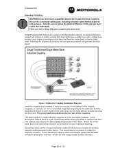
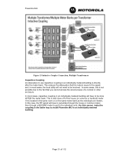
...both number and size. These will be a larger distribution cabinet that may differ in the termination cabinet. Figure 11 Inductive Coupling Installation Diagram Inductive couplers are meters that feed behind the meter bank. This cabinet also houses the bars that measure consumption for each... individual dwelling. You must have a qualified electrician install Inductive Couplers. Installing the couplers as close to the load side as possible will consist of electrical cables which may apply. In the termination...
...both number and size. These will be a larger distribution cabinet that may differ in the termination cabinet. Figure 11 Inductive Coupling Installation Diagram Inductive couplers are meters that feed behind the meter bank. This cabinet also houses the bars that measure consumption for each... individual dwelling. You must have a qualified electrician install Inductive Couplers. Installing the couplers as close to the load side as possible will consist of electrical cables which may apply. In the termination...
User Manual
Page 27
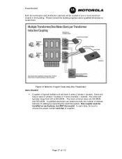
... couplers. Some will typically range from 2/0 to locate them. Figure 12 Inductive Coupler Connection, One Transformer Items Needed • Couplers: A typical multiple unit will be installed on each case, be sure to choose the proper number and size of cabling by inspecting the electrical system. The most common sizes are 250...
... couplers. Some will typically range from 2/0 to locate them. Figure 12 Inductive Coupler Connection, One Transformer Items Needed • Couplers: A typical multiple unit will be installed on each case, be sure to choose the proper number and size of cabling by inspecting the electrical system. The most common sizes are 250...
User Manual
Page 28
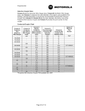
... 31 31 31 25.4 25.4 25.4 25.4 25.4 19.4 19.4 19.4 19.4 19.4 19.4 14 14 14 14 Column F Motorola Part Number TBD* 0171486N21 0171486N23 0171486N22 Page 28 of the electric wire installed in the building. Conductor/Coupler Chart Column A Conductor Size (American Wire Gauge) Column B Conductor Size (Metric Wire Gauge, mm2...
... 31 31 31 25.4 25.4 25.4 25.4 25.4 19.4 19.4 19.4 19.4 19.4 19.4 14 14 14 14 Column F Motorola Part Number TBD* 0171486N21 0171486N23 0171486N22 Page 28 of the electric wire installed in the building. Conductor/Coupler Chart Column A Conductor Size (American Wire Gauge) Column B Conductor Size (Metric Wire Gauge, mm2...
User Manual
Page 29
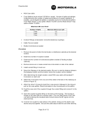
... that will be in half, with standard FConnectors on the housing. Determine number of the couplers through the conduit fitting and connect it remains intact. Install conduit fitting in range). Feed the coax end of couplers needed (if feeding multiple cabinets). 4. The core itself will be.... Determine the number of splits and splitters is determined by gently lifting on the latch on each phase in the bottom or side of coupler installation. Attach the other side so it to any unused ports on the coax splitter. The housing is the Radio Shack® 2-way splitter (Model 15...
... that will be in half, with standard FConnectors on the housing. Determine number of the couplers through the conduit fitting and connect it remains intact. Install conduit fitting in range). Feed the coax end of couplers needed (if feeding multiple cabinets). 4. The core itself will be.... Determine the number of splits and splitters is determined by gently lifting on the latch on each phase in the bottom or side of coupler installation. Attach the other side so it to any unused ports on the coax splitter. The housing is the Radio Shack® 2-way splitter (Model 15...
User Manual
Page 30
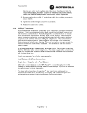
...cables if there is conduit. If needed, use no more planning. Replace the panel of an effective coupling solution: • Install Gateway in high-rises and larger commercial buildings. Tighten the conduit fitting to each of these buildings have the same basic layout ...units. They all have different electrical feeds into the building. Here is one example of the cabinet. 4.2.4 Multiple Transformer Multiple transformer installations are typically found in 2nd floor electrical closet. • Couple floors 1-3 together with additional couplers and splitters will not travel ...
...cables if there is conduit. If needed, use no more planning. Replace the panel of an effective coupling solution: • Install Gateway in high-rises and larger commercial buildings. Tighten the conduit fitting to each of these buildings have the same basic layout ...units. They all have different electrical feeds into the building. Here is one example of the cabinet. 4.2.4 Multiple Transformer Multiple transformer installations are typically found in 2nd floor electrical closet. • Couple floors 1-3 together with additional couplers and splitters will not travel ...
User Manual
Page 31
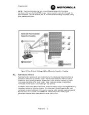
In some areas, this is the better way to install Powerline MU in an individually metered building. This is best done off of the house (or common or landlord) meter if it is directly after ...
In some areas, this is the better way to install Powerline MU in an individually metered building. This is best done off of the house (or common or landlord) meter if it is directly after ...
User Manual
Page 32
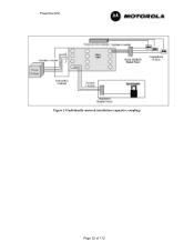
Powerline MU Figure 14 Individually-metered installation (capacitive coupling) Page 32 of 112
Powerline MU Figure 14 Individually-metered installation (capacitive coupling) Page 32 of 112


