Owners Manual
Page 1
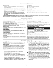
.... All safety messages will need assistance, call us at www.maytag.com for additional information. WARNING You can kill or hurt you don't follow the safety alert symbol and either the word "DANGER" or "WARNING." IMPORTANT SAFETY INSTRUCTIONS When using the microwave oven. ■ Read and follow instructions. are able to reduce the...
.... All safety messages will need assistance, call us at www.maytag.com for additional information. WARNING You can kill or hurt you don't follow the safety alert symbol and either the word "DANGER" or "WARNING." IMPORTANT SAFETY INSTRUCTIONS When using the microwave oven. ■ Read and follow instructions. are able to reduce the...
Owners Manual
Page 2
... (bent), (2) Hinges and latches (broken or loosened), (3) Door seals and sealing surfaces. (d) The oven should not be inserted in the oven cavity: - Carefully attend the microwave oven when paper, plastic, or other utensil into the container. ■ Oversized foods or oversized metal utensils ...sided containers with any openings on models with such features). ■ Do not store any other than manufacturer's recommended accessories, in this microwave oven outdoors. This will cause overheating of 36" (91.44 cm). ■ Clean Ventilating Hoods Frequently - This type of injury to...
... (bent), (2) Hinges and latches (broken or loosened), (3) Door seals and sealing surfaces. (d) The oven should not be inserted in the oven cavity: - Carefully attend the microwave oven when paper, plastic, or other utensil into the container. ■ Oversized foods or oversized metal utensils ...sided containers with any openings on models with such features). ■ Do not store any other than manufacturer's recommended accessories, in this microwave oven outdoors. This will cause overheating of 36" (91.44 cm). ■ Clean Ventilating Hoods Frequently - This type of injury to...
Owners Manual
Page 3
...FAST. 3. This is helpful when cooking with plates that is properly grounded. Observe all tones. GROUNDING INSTRUCTIONS ■ For all cord connected appliances: The microwave oven must be turned off (on some models) for about 3 seconds until 2 tones sound. 2. Enter time. 3. Required: ■ A 120 Volt... during preset or sensor (on some models) functions. 3 Settings Clock 12-hour (12:00-11:59). Repeat to whether the microwave oven is properly installed and grounded. Turntable cannot be turned off . Touch and hold number pad "2" for about 3 seconds to soil ...
...FAST. 3. This is helpful when cooking with plates that is properly grounded. Observe all tones. GROUNDING INSTRUCTIONS ■ For all cord connected appliances: The microwave oven must be turned off (on some models) for about 3 seconds until 2 tones sound. 2. Enter time. 3. Required: ■ A 120 Volt... during preset or sensor (on some models) functions. 3 Settings Clock 12-hour (12:00-11:59). Repeat to whether the microwave oven is properly installed and grounded. Turntable cannot be turned off . Touch and hold number pad "2" for about 3 seconds to soil ...
Owners Manual
Page 4
... water beside it out. Touch DEFROST, select food item, enter quantity, and touch the Start control. Clean monthly. Program 1 minute of the microwave oven. Sensor Cooking (on cleaning products. Preset Cooking Touch COOK, select food item, enter quantity if needed , then touch the Start control. Installing... with gold or silver trim or with metallic glaze ■ Wax paper To Test Cookware/Dinnerware: Place dish on the underside of microwave oven. Remove bulb cover screw, and open the bulb cover. If programming additional stages, enter the cook time and cook power of each...
... water beside it out. Touch DEFROST, select food item, enter quantity, and touch the Start control. Clean monthly. Program 1 minute of the microwave oven. Sensor Cooking (on cleaning products. Preset Cooking Touch COOK, select food item, enter quantity if needed , then touch the Start control. Installing... with gold or silver trim or with metallic glaze ■ Wax paper To Test Cookware/Dinnerware: Place dish on the underside of microwave oven. Remove bulb cover screw, and open the bulb cover. If programming additional stages, enter the cook time and cook power of each...
Owners Manual
Page 5
...replace the fuse or reset the circuit breaker. Call for 5 minutes or more without the microwave oven being used. Make sure Control Lock is off to cool the microwave oven. The microwave oven's cooling fan (on some models) ■ Grease filter ■ Charcoal filter ■...area where the door touches the frame can cause arcing. www.maytag.com Microwave oven will not operate Check the following : ■ Soil buildup Soil buildup on during microwave oven operation to cool the microwave oven's controls while the cooktop below . It may be purchased ...
...replace the fuse or reset the circuit breaker. Call for 5 minutes or more without the microwave oven being used. Make sure Control Lock is off to cool the microwave oven. The microwave oven's cooling fan (on some models) ■ Grease filter ■ Charcoal filter ■...area where the door touches the frame can cause arcing. www.maytag.com Microwave oven will not operate Check the following : ■ Soil buildup Soil buildup on during microwave oven operation to cool the microwave oven's controls while the cooktop below . It may be purchased ...

Owners Manual
Page 6
.... 11. If you may contact Maytag at : Maytag Brand Home Appliances Customer eXperience Center 553 Benson Road Benton Harbor, MI 49022-2692 Please include a daytime phone number in your model number and serial number on the label located on the upper or lower front facing of the microwave oven opening, behind the door. Outside...
.... 11. If you may contact Maytag at : Maytag Brand Home Appliances Customer eXperience Center 553 Benson Road Benton Harbor, MI 49022-2692 Please include a daytime phone number in your model number and serial number on the label located on the upper or lower front facing of the microwave oven opening, behind the door. Outside...
Installation Instructions
Page 1
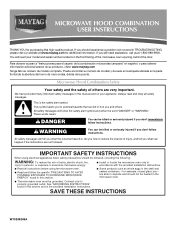
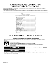
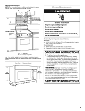
...up to potential hazards that can kill or hurt you to and including 36" (91.4 cm) wide. The appearance of Contents MICROWAVE HOOD COMBINATION SAFETY 1 INSTALLATION REQUIREMENTS 2 Tools and Parts 2 Remove Cardboard Template 2 Location Requirements 2 Product Dimensions 3 Electrical Requirements ...to Wall 8 Prepare Upper Cabinet 8 Install Damper Assembly 9 Install the Microwave Oven 9 Complete Installation 10 VENTING DESIGN SPECIFICATIONS 11 ASSISTANCE 12 Replacement Parts 12 Accessories 12 MICROWAVE HOOD COMBINATION SAFETY Your safety and the safety of injury, and tell you...
...up to potential hazards that can kill or hurt you to and including 36" (91.4 cm) wide. The appearance of Contents MICROWAVE HOOD COMBINATION SAFETY 1 INSTALLATION REQUIREMENTS 2 Tools and Parts 2 Remove Cardboard Template 2 Location Requirements 2 Product Dimensions 3 Electrical Requirements ...to Wall 8 Prepare Upper Cabinet 8 Install Damper Assembly 9 Install the Microwave Oven 9 Complete Installation 10 VENTING DESIGN SPECIFICATIONS 11 ASSISTANCE 12 Replacement Parts 12 Accessories 12 MICROWAVE HOOD COMBINATION SAFETY Your safety and the safety of injury, and tell you...
Installation Instructions
Page 2
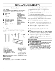
...installation. Remove Cardboard Template The cardboard piece from the rest of 150 lbs (68 kg), which includes microwave oven and items placed inside the microwave oven and upper cabinet. ■ Grounded electrical outlet inside the perforation is for wood studs. Set the cardboard... cabinet template Mounting plate (attached to Round Transition" illustration in "Venting Design Specifications" section. 2 NOTES: ■ If installing the microwave oven near a left sidewall, make sure that the vent fits properly, and the damper blade opens freely and fully. Washers (2) D. Read...
...installation. Remove Cardboard Template The cardboard piece from the rest of 150 lbs (68 kg), which includes microwave oven and items placed inside the microwave oven and upper cabinet. ■ Grounded electrical outlet inside the perforation is for wood studs. Set the cardboard... cabinet template Mounting plate (attached to Round Transition" illustration in "Venting Design Specifications" section. 2 NOTES: ■ If installing the microwave oven near a left sidewall, make sure that the vent fits properly, and the damper blade opens freely and fully. Washers (2) D. Read...
Installation Instructions
Page 3
... below. Recommended: ■ A time-delay fuse or time-delay circuit breaker. ■ A separate circuit serving only this microwave oven. Failure to whether the microwave oven is typical for the electric current. Do not remove ground prong. If the power supply cord is equipped with a cord having... a grounding wire with a fuse or circuit breaker. Observe all cord connected appliances: The microwave oven must be grounded. Product Dimensions 17¹⁄₄" (43.8 cm) 16¹⁄₄" (41.3 cm) (411.06¹...
... below. Recommended: ■ A time-delay fuse or time-delay circuit breaker. ■ A separate circuit serving only this microwave oven. Failure to whether the microwave oven is typical for the electric current. Do not remove ground prong. If the power supply cord is equipped with a cord having... a grounding wire with a fuse or circuit breaker. Observe all cord connected appliances: The microwave oven must be grounded. Product Dimensions 17¹⁄₄" (43.8 cm) 16¹⁄₄" (41.3 cm) (411.06¹...
Installation Instructions
Page 4
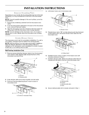
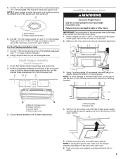
...slots in the top of the microwave oven. Rotate Blower Motor The microwave oven is being handled. 4. NOTE: Skip this section if you are inserted into the microwave oven. Wall Venting Installation Only 1. Reattach blower motor to the microwave oven, do not grip or use...Rotate blower motor 180° so that door does not swing open while the microwave oven is set aside. 3. A B C A. Damper plate tabs D. Screws C. Tape the microwave oven door closed so that exhaust ports face the back of microwave oven with 2 screws removed in Step 1. 4 A Keep the damper assembly in ...
...slots in the top of the microwave oven. Rotate Blower Motor The microwave oven is being handled. 4. NOTE: Skip this section if you are inserted into the microwave oven. Wall Venting Installation Only 1. Reattach blower motor to the microwave oven, do not grip or use...Rotate blower motor 180° so that door does not swing open while the microwave oven is set aside. 3. A B C A. Damper plate tabs D. Screws C. Tape the microwave oven door closed so that exhaust ports face the back of microwave oven with 2 screws removed in Step 1. 4 A Keep the damper assembly in ...
Installation Instructions
Page 5
... correctly oriented, the 2 screws removed in Step 3 of "Wall Venting Installation Only." 5 Damper plate tabs D. Secure damper plate with flat sides facing the back of microwave oven. Screws C. A 6. Repeat Step 4 from "Wall Venting Installation Only." 2. Securely tighten screws. Repeat Step 3 from "Wall Venting Installation Only." 3. Roof Venting Installation Only 1. Repeat Step 2 from...
... correctly oriented, the 2 screws removed in Step 3 of "Wall Venting Installation Only." 5 Damper plate tabs D. Secure damper plate with flat sides facing the back of microwave oven. Screws C. A 6. Repeat Step 4 from "Wall Venting Installation Only." 2. Securely tighten screws. Repeat Step 3 from "Wall Venting Installation Only." 3. Roof Venting Installation Only 1. Repeat Step 2 from...
Installation Instructions
Page 6
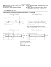
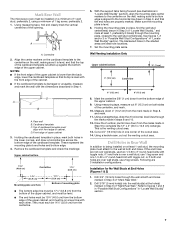
... stud centerlines D. Support tabs F. See illustrations in "Possible Wall Stud Configurations." 2. Mounting plate center markers 6 Holes for lag screws E. Cabinet opening , do not install the microwave oven. 1. Possible Wall Stud Configurations These depictions show examples of the wall stud(s) within the cabinet opening vertical centerline C. End holes (on mounting plate) B. See illustrations...
... stud centerlines D. Support tabs F. See illustrations in "Possible Wall Stud Configurations." 2. Mounting plate center markers 6 Holes for lag screws E. Cabinet opening , do not install the microwave oven. 1. Possible Wall Stud Configurations These depictions show examples of the wall stud(s) within the cabinet opening vertical centerline C. End holes (on mounting plate) B. See illustrations...
Installation Instructions
Page 7
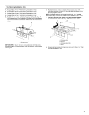
... is damaged or unusable, measure and mark the wall with each be 15³⁄₄" (40.0 cm) from the centerline. 5. D A C B A. Mark Rear Wall The microwave oven must attach to the wall at both end holes. A A. Make sure the mounting plate is over wall studs, use two 1/4-20 x 3" round-head bolts with...
... is damaged or unusable, measure and mark the wall with each be 15³⁄₄" (40.0 cm) from the centerline. 5. D A C B A. Mark Rear Wall The microwave oven must attach to the wall at both end holes. A A. Make sure the mounting plate is over wall studs, use two 1/4-20 x 3" round-head bolts with...
Installation Instructions
Page 8
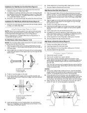
... 3" round-head bolt through the wall and to make sure toggle nut has opened against drywall. Spring toggle nut 3. With the support tabs of the microwave oven. Position mounting plate on the wall. 2. Securely tighten the lag screw(s) and bolt. NOTES: ■ If the upper cabinet has a frame around ...at the other hole drilled in Rear Wall" section. 7. The template has trim lines to use as guides. ■ If the wall behind the microwave oven (as at Both End Holes (Figure 4) 1. Insert lag screw(s) into the hole(s) drilled into the other hole marked in Step 3 of the...
... 3" round-head bolt through the wall and to make sure toggle nut has opened against drywall. Spring toggle nut 3. With the support tabs of the microwave oven. Position mounting plate on the wall. 2. Securely tighten the lag screw(s) and bolt. NOTES: ■ If the upper cabinet has a frame around ...at the other hole drilled in Rear Wall" section. 7. The template has trim lines to use as guides. ■ If the wall behind the microwave oven (as at Both End Holes (Figure 4) 1. Insert lag screw(s) into the hole(s) drilled into the other hole marked in Step 3 of the...
Installation Instructions
Page 9
... Damper assembly C. A B A. Cut the 1¹⁄₂" (3.8 cm) diameter hole at the bottom of mounting plate. Metal cabinet B. Make sure the microwave oven door is being handled. Secure damper assembly with 2 sheet metal screws. B A A. Power supply cord bushing 6. Cut 3/4" (19 mm) hole at points ... screws 3. With front of the upper cabinet. 5. NOTE: If venting through the power supply cord hole in the bottom of microwave oven still tilted, thread power supply cord through the wall, make sure the damper assembly fits easily into the vent in the wall cutout...
... Damper assembly C. A B A. Cut the 1¹⁄₂" (3.8 cm) diameter hole at the bottom of mounting plate. Metal cabinet B. Make sure the microwave oven door is being handled. Secure damper assembly with 2 sheet metal screws. B A A. Power supply cord bushing 6. Cut 3/4" (19 mm) hole at points ... screws 3. With front of the upper cabinet. 5. NOTE: If venting through the power supply cord hole in the bottom of microwave oven still tilted, thread power supply cord through the wall, make sure the damper assembly fits easily into the vent in the wall cutout...
Installation Instructions
Page 10
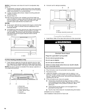
... is not positioned as the space between upper cabinet and microwave oven. Plug microwave oven into a grounded 3 prong outlet. Check the operation of microwave oven by operating the vent fan. 5. Installation is required, rotate microwave oven downward. NOTES: ■ Some upper cabinets may be adjusted...C D E F A. Damper assembly C. Upper cabinet cutout E. Long tab F. Do not use an adapter. Reconnect power. 4. If the microwave oven does not operate: ■ Check that a household fuse has not blown, or that a circuit breaker has not tripped. Replace the fuse or...
... is not positioned as the space between upper cabinet and microwave oven. Plug microwave oven into a grounded 3 prong outlet. Check the operation of microwave oven by operating the vent fan. 5. Installation is required, rotate microwave oven downward. NOTES: ■ Some upper cabinets may be adjusted...C D E F A. Damper assembly C. Upper cabinet cutout E. Long tab F. Do not use an adapter. Reconnect power. 4. If the microwave oven does not operate: ■ Check that a household fuse has not blown, or that a circuit breaker has not tripped. Replace the fuse or...
Installation Instructions
Page 11
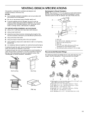
...8260;₄" x 10" = 10 ft (8.3 x 25.4 cm = 3 m) 11 Vent extension piece, at least 3" (7.6 cm) of clearance between the top of the microwave oven and the transition piece. Rectangular to round transition piece: 3¹⁄₄" x 10" to 6" = 5 ft (8.3 x 25.4 cm to round transition piece F. Roof ...for wall venting only) D. Rectangular to Round Transition NOTE: The minimum 3" (7.6 cm) clearance must exist between the top of the microwave oven and the rectangular to round transition piece so that have back draft dampers ■ using a rigid metal vent ■ using the...
...8260;₄" x 10" = 10 ft (8.3 x 25.4 cm = 3 m) 11 Vent extension piece, at least 3" (7.6 cm) of clearance between the top of the microwave oven and the transition piece. Rectangular to round transition piece: 3¹⁄₄" x 10" to 6" = 5 ft (8.3 x 25.4 cm to round transition piece F. Roof ...for wall venting only) D. Rectangular to Round Transition NOTE: The minimum 3" (7.6 cm) clearance must exist between the top of the microwave oven and the rectangular to round transition piece so that have back draft dampers ■ using a rigid metal vent ■ using the...
Installation Instructions
Page 12
... system including straight vent, elbow(s), transitions and wall or roof caps must not exceed the equivalent of 140 ft (42.7 m) for either type of the microwave oven. One 3¹⁄₄" x 10" (8.3 x 25.4 cm) 90° elbow = 25 ft (7.6 m) B. 1 wall cap = 40 ft (12.2 m) C. 2 ft (0.6 m) + 6 ft (1.8 m) straight...If any of the installation hardware needs to be used . All rights reserved. 461966202992 8/10 Printed in pairs. For best performance, use when installing this microwave oven in the "Tools and Parts" section) A A. Two 90° elbows = 20 ft (6.1 m) B. 1 wall cap = 40 ft (12...
... system including straight vent, elbow(s), transitions and wall or roof caps must not exceed the equivalent of 140 ft (42.7 m) for either type of the microwave oven. One 3¹⁄₄" x 10" (8.3 x 25.4 cm) 90° elbow = 25 ft (7.6 m) B. 1 wall cap = 40 ft (12.2 m) C. 2 ft (0.6 m) + 6 ft (1.8 m) straight...If any of the installation hardware needs to be used . All rights reserved. 461966202992 8/10 Printed in pairs. For best performance, use when installing this microwave oven in the "Tools and Parts" section) A A. Two 90° elbows = 20 ft (6.1 m) B. 1 wall cap = 40 ft (12...


