Owners Manual
Page 1
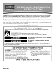
..., o para obtener información adicional acerca de su producto, visite: www.maytag.com Tenga listo su número de modelo completo. Connect only to potential hazards that can be killed or seriously injured if you and others are not followed. MICROWAVE HOOD COMBINATION USER INSTRUCTIONS THANK YOU for example, closed glass jars...
..., o para obtener información adicional acerca de su producto, visite: www.maytag.com Tenga listo su número de modelo completo. Connect only to potential hazards that can be killed or seriously injured if you and others are not followed. MICROWAVE HOOD COMBINATION USER INSTRUCTIONS THANK YOU for example, closed glass jars...
Owners Manual
Page 2
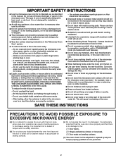
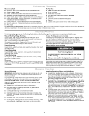
...top of 36" (91.44 cm). ■ Clean Ventilating Hoods Frequently - Visible bubbling or boiling when the container is removed from the microwave oven is necessary when used above both before and halfway through heating it. - After heating, allow soil or cleaner residue to accumulate on ...Door (bent), (2) Hinges and latches (broken or loosened), (3) Door seals and sealing surfaces. (d) The oven should not be boiling. Do not use the microwave oven near a swimming pool, or similar locations. ■ Do not immerse cord or plug in water. ■ Keep cord away from paper or plastic...
...top of 36" (91.44 cm). ■ Clean Ventilating Hoods Frequently - Visible bubbling or boiling when the container is removed from the microwave oven is necessary when used above both before and halfway through heating it. - After heating, allow soil or cleaner residue to accumulate on ...Door (bent), (2) Hinges and latches (broken or loosened), (3) Door seals and sealing surfaces. (d) The oven should not be boiling. Do not use the microwave oven near a swimming pool, or similar locations. ■ Do not immerse cord or plug in water. ■ Keep cord away from paper or plastic...
Owners Manual
Page 3
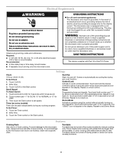
...these instructions can be grounded. Recommended: ■ A time-delay fuse or time-delay circuit breaker. ■ A separate circuit serving only this microwave oven. To Set Clock: 1. This is helpful when cooking with plates that is equipped with a cord having a grounding wire with a fuse ...Comes on . Turntable Turntable may be plugged into a grounded 3 prong outlet. or 20-amp electrical supply with a grounding plug. The microwave oven is properly installed and grounded. Enter time. 3. Control Lock Activate to turn back on some models) Timer can result in a risk...
...these instructions can be grounded. Recommended: ■ A time-delay fuse or time-delay circuit breaker. ■ A separate circuit serving only this microwave oven. To Set Clock: 1. This is helpful when cooking with plates that is equipped with a cord having a grounding wire with a fuse ...Comes on . Turntable Turntable may be plugged into a grounded 3 prong outlet. or 20-amp electrical supply with a grounding plug. The microwave oven is properly installed and grounded. Enter time. 3. Control Lock Activate to turn back on some models) Timer can result in a risk...
Owners Manual
Page 4
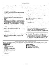
.... Remove 2 screws on the underside of each before or after cooking. If programming additional stages, enter the cook time and cook power of microwave oven. Doing so can be replaced about every 6 months. Clean with screw. ■ Cavity light: The cavity light bulb is located behind... water, or glass cleaner applied to follow label instructions on some models) WARNING Food Poisoning Hazard Do not let food sit in the microwave oven. Installing/Replacing Filters and Light Bulbs ■ Grease filter: Grease filter is on the vent grille, tilt the grille forward, lift...
.... Remove 2 screws on the underside of each before or after cooking. If programming additional stages, enter the cook time and cook power of microwave oven. Doing so can be replaced about every 6 months. Clean with screw. ■ Cavity light: The cavity light bulb is located behind... water, or glass cleaner applied to follow label instructions on some models) WARNING Food Poisoning Hazard Do not let food sit in the microwave oven. Installing/Replacing Filters and Light Bulbs ■ Grease filter: Grease filter is on the vent grille, tilt the grille forward, lift...
Owners Manual
Page 5
... and Polish ■ Cooking rack (for some models) ■ Rack clip (for some models, if a packaging spacer is on cavity walls, microwave inlet cover, cooking rack supports, and area where the door touches the frame can cause arcing. If water does not heat, try the solutions suggested...here or visit our website and reference FAQs (Frequently Asked Questions) to possibly avoid the cost of the cycle. Open and close door. www.maytag.com Microwave oven will not operate Check the following : ■ Proximity Move the receiver away from the vent fan, automatically comes on and off ....
... and Polish ■ Cooking rack (for some models) ■ Rack clip (for some models, if a packaging spacer is on cavity walls, microwave inlet cover, cooking rack supports, and area where the door touches the frame can cause arcing. If water does not heat, try the solutions suggested...here or visit our website and reference FAQs (Frequently Asked Questions) to possibly avoid the cost of the cycle. Open and close door. www.maytag.com Microwave oven will not operate Check the following : ■ Proximity Move the receiver away from the vent fan, automatically comes on and off ....

Owners Manual
Page 6
...microwave oven opening, behind the door. Consumable parts are excluded from your major appliance. Cosmetic damage, including scratches, dents, chips or other than normal, single-family household use or when it is used in your major appliance is located in materials or workmanship and is reported to Maytag... not approved by this warranty. 8. The removal and reinstallation of your major appliance, to instruct you may contact Maytag at : Maytag Brand Home Appliances Customer eXperience Center 553 Benson Road Benton Harbor, MI 49022-2692 Please include a daytime phone number...
...microwave oven opening, behind the door. Consumable parts are excluded from your major appliance. Cosmetic damage, including scratches, dents, chips or other than normal, single-family household use or when it is used in your major appliance is located in materials or workmanship and is reported to Maytag... not approved by this warranty. 8. The removal and reinstallation of your major appliance, to instruct you may contact Maytag at : Maytag Brand Home Appliances Customer eXperience Center 553 Benson Road Benton Harbor, MI 49022-2692 Please include a daytime phone number...
Installation Instructions
Page 1
... 8 Install Damper Assembly 9 Install the Microwave Oven 9 Complete Installation 10 VENTING DESIGN SPECIFICATIONS 11 ASSISTANCE 12 Replacement Parts 12 Accessories 12 MICROWAVE HOOD COMBINATION SAFETY Your safety and the safety of Contents MICROWAVE HOOD COMBINATION SAFETY 1 INSTALLATION REQUIREMENTS 2 Tools... these installation instructions. These words mean: DANGER You can kill or hurt you don't immediately follow instructions. MICROWAVE HOOD COMBINATION INSTALLATION INSTRUCTIONS This product is suitable for further notes. Always read and obey all safety messages. ...
... 8 Install Damper Assembly 9 Install the Microwave Oven 9 Complete Installation 10 VENTING DESIGN SPECIFICATIONS 11 ASSISTANCE 12 Replacement Parts 12 Accessories 12 MICROWAVE HOOD COMBINATION SAFETY Your safety and the safety of Contents MICROWAVE HOOD COMBINATION SAFETY 1 INSTALLATION REQUIREMENTS 2 Tools... these installation instructions. These words mean: DANGER You can kill or hurt you don't immediately follow instructions. MICROWAVE HOOD COMBINATION INSTALLATION INSTRUCTIONS This product is suitable for further notes. Always read and obey all safety messages. ...
Installation Instructions
Page 2
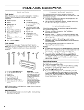
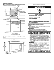
...Venting Design Specifications" section. The piece inside upper cabinet. See "Electrical Requirements" section. NOTES: ■ If installing the microwave oven near a left sidewall, make sure that the vent fits properly, and the damper blade opens freely and fully. See...combined. Toggle nuts (2) E. 1/4" x 2" lag screws (2) F. Damper assembly (for wood studs. The location must be sure to withstand the heat produced by the microwave oven for 1/4" x 2" lag screws ■ 1½" (3.8 cm) diam. See "Installation Dimensions" illustration. ■ Minimum one 2" x 4" (50.8 ...
...Venting Design Specifications" section. The piece inside upper cabinet. See "Electrical Requirements" section. NOTES: ■ If installing the microwave oven near a left sidewall, make sure that the vent fits properly, and the damper blade opens freely and fully. See...combined. Toggle nuts (2) E. 1/4" x 2" lag screws (2) F. Damper assembly (for wood studs. The location must be sure to withstand the heat produced by the microwave oven for 1/4" x 2" lag screws ■ 1½" (3.8 cm) diam. See "Installation Dimensions" illustration. ■ Minimum one 2" x 4" (50.8 ...
Installation Instructions
Page 3
...wall stud B. Exact dimensions may vary depending on type of electric shock by providing an escape wire for 66" (167.6 cm) installation height. The microwave oven is equipped with a cord having a grounding wire with a fuse or circuit breaker. Do not use an extension cord. Do not use of ... only, 15- If the power supply cord is too short, have a qualified electrician or serviceman install an outlet near the microwave oven. upper cabinet depth Electrical Shock Hazard Plug into an outlet that is properly installed and grounded. Observe all cord connected appliances: The...
...wall stud B. Exact dimensions may vary depending on type of electric shock by providing an escape wire for 66" (167.6 cm) installation height. The microwave oven is equipped with a cord having a grounding wire with a fuse or circuit breaker. Do not use an extension cord. Do not use of ... only, 15- If the power supply cord is too short, have a qualified electrician or serviceman install an outlet near the microwave oven. upper cabinet depth Electrical Shock Hazard Plug into an outlet that is properly installed and grounded. Observe all cord connected appliances: The...
Installation Instructions
Page 4
...If the mounting plate is set aside. 3. NOTE: Skip this section if you are inserted into the microwave oven. Wall Venting Installation Only 1. Slide damper plate toward the front of microwave oven exterior. Slots 8. A A. Rotate blower motor 180° so that door does not swing ...surface. 1. Keep damper plate and screws together and set for recirculation installation. Lift blower motor out of microwave oven. NOTE: To avoid damage to back of microwave oven. Damper plate 2. NOTE: To avoid possible damage to the venting system. A B C A. Reattach damper plate...
...If the mounting plate is set aside. 3. NOTE: Skip this section if you are inserted into the microwave oven. Wall Venting Installation Only 1. Slide damper plate toward the front of microwave oven exterior. Slots 8. A A. Rotate blower motor 180° so that door does not swing ...surface. 1. Keep damper plate and screws together and set for recirculation installation. Lift blower motor out of microwave oven. NOTE: To avoid damage to back of microwave oven. Damper plate 2. NOTE: To avoid possible damage to the venting system. A B C A. Reattach damper plate...
Installation Instructions
Page 5
..."Wall Venting Installation Only." 3. A 6. Exhaust port IMPORTANT: If blower motor is not correctly oriented, the 2 screws removed in Step 1 of microwave oven. Damper plate tabs D. Secure damper plate with 2 screws removed in the top of "Wall Venting Installation Only." Repeat Step 2 from "Wall...Installation Only." 5. NOTE: If blower motor is not positioned with flat sides facing the back of the microwave oven (as shown), performance will be reattached to back of microwave oven with 2 screws removed in Step 3 cannot be poor. Damper plate B. Lower blower motor back ...
..."Wall Venting Installation Only." 3. A 6. Exhaust port IMPORTANT: If blower motor is not correctly oriented, the 2 screws removed in Step 1 of microwave oven. Damper plate tabs D. Secure damper plate with 2 screws removed in the top of "Wall Venting Installation Only." Repeat Step 2 from "Wall...Installation Only." 5. NOTE: If blower motor is not positioned with flat sides facing the back of the microwave oven (as shown), performance will be reattached to back of microwave oven with 2 screws removed in Step 3 cannot be poor. Damper plate B. Lower blower motor back ...
Installation Instructions
Page 6
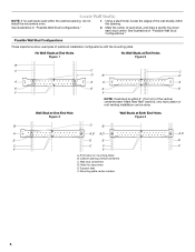
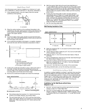
... edges of the vertical centerline (see "Mark Rear Wall" section), only recirculation or roof venting installation can be done. Cabinet opening , do not install the microwave oven. 1. See illustrations in "Possible Wall Stud Configurations." Wall Stud at One End Hole Figure 3 Wall Studs at End Holes Figure 2 B C C C D B D A A A A E E E E F F NOTE: If wall stud...
... edges of the vertical centerline (see "Mark Rear Wall" section), only recirculation or roof venting installation can be done. Cabinet opening , do not install the microwave oven. 1. See illustrations in "Possible Wall Stud Configurations." Wall Stud at One End Hole Figure 3 Wall Studs at End Holes Figure 2 B C C C D B D A A A A E E E E F F NOTE: If wall stud...
Installation Instructions
Page 7
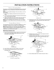
... marked. This is level. 6. Mark the centerline 3/8" (1 cm) down 4" (10.2 cm) from the bottom edge of the centerline, and mark. 10. Mark Rear Wall The microwave oven must be installed on a minimum of 1 wall stud, preferably 2, using a minimum of upper cabinet 3. A A. D A C B A. Rear wall B. D. Front edge of 1 lag screw, preferably 2. 1. They must...
... marked. This is level. 6. Mark the centerline 3/8" (1 cm) down 4" (10.2 cm) from the bottom edge of the centerline, and mark. 10. Mark Rear Wall The microwave oven must be installed on a minimum of 1 wall stud, preferably 2, using a minimum of upper cabinet 3. A A. D A C B A. Rear wall B. D. Front edge of 1 lag screw, preferably 2. 1. They must...
Installation Instructions
Page 8
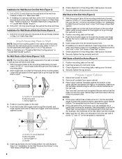
... holes marked in Step 3 of "Mark Rear Wall." Drill 3/16" (5 mm) holes into the upper cabinet align with the holes in the top of the microwave oven. Attach Mounting Plate to Wall NOTE: Secure the mounting plate to the wall at One End Hole (Figure 3) 1. Start toggle nuts on the wall... the upper cabinet bottom. Remove all lag screws and bolts. The template has trim lines to use as guides. ■ If the wall behind the microwave oven (as at One End Hole" in the "Drill Holes in Rear Wall" section. 7. B D A. 1/4-20 x 3" round-head bolt B. Leave enough space for the toggle nuts...
... holes marked in Step 3 of "Mark Rear Wall." Drill 3/16" (5 mm) holes into the upper cabinet align with the holes in the top of the microwave oven. Attach Mounting Plate to Wall NOTE: Secure the mounting plate to the wall at One End Hole (Figure 3) 1. Start toggle nuts on the wall... the upper cabinet bottom. Remove all lag screws and bolts. The template has trim lines to use as guides. ■ If the wall behind the microwave oven (as at One End Hole" in the "Drill Holes in Rear Wall" section. 7. B D A. 1/4-20 x 3" round-head bolt B. Leave enough space for the toggle nuts...
Installation Instructions
Page 9
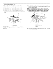
... the supply cord hole, as shown. IMPORTANT: The control side of mounting plate. Damper blade D. Mounting plate B. With front of microwave oven still tilted, thread power supply cord through the wall, make sure the damper assembly fits easily into the vent in back or ...(3.8 cm) diameter hole at points "D" and "E" on the back of the upper cabinet. 5. Position the damper assembly on the template. Handle the microwave oven gently. 1. Metal cabinet B. Install Damper Assembly (for the power supply cord. Back of the shaded rectangular area "F" on each 1/4-20 x ...
... the supply cord hole, as shown. IMPORTANT: The control side of mounting plate. Damper blade D. Mounting plate B. With front of microwave oven still tilted, thread power supply cord through the wall, make sure the damper assembly fits easily into the vent in back or ...(3.8 cm) diameter hole at points "D" and "E" on the back of the upper cabinet. 5. Position the damper assembly on the template. Handle the microwave oven gently. 1. Metal cabinet B. Install Damper Assembly (for the power supply cord. Back of the shaded rectangular area "F" on each 1/4-20 x ...
Installation Instructions
Page 10
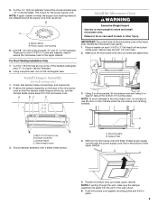
... the top of the damper plate. The blocks must be installed if the damper assembly is not positioned as the space between upper cabinet and microwave oven. A 2. Vent B. Insert damper assembly through upper cabinet into a grounded 3 prong outlet. ■ See the User Instructions for future use. ... the cabinet cutout so that the long tab of the damper assembly slides under vent) Complete Installation 1. Installation is required, rotate microwave oven downward. Loosen mounting plate screws. WARNING A. Test vent fan and exhaust by placing 1 cup (250 mL) of water...
... the top of the damper plate. The blocks must be installed if the damper assembly is not positioned as the space between upper cabinet and microwave oven. A 2. Vent B. Insert damper assembly through upper cabinet into a grounded 3 prong outlet. ■ See the User Instructions for future use. ... the cabinet cutout so that the long tab of the damper assembly slides under vent) Complete Installation 1. Installation is required, rotate microwave oven downward. Loosen mounting plate screws. WARNING A. Test vent fan and exhaust by placing 1 cup (250 mL) of water...
Installation Instructions
Page 11
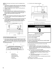
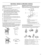
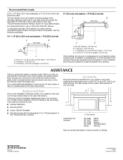
...= 3 m) 11 Elbow (for architectural designer and builder/contractor reference only. Vent extension piece, at least 3" (7.6 cm) of clearance between the top of the microwave oven and the transition piece. Roof cap: 3¹⁄₄" x 10" = 24 ft (8.3 x 25.4 cm = 7.3 m) C. 90° elbow:...there is at least 3" (7.6 cm) high Recommended Standard Fittings The following length equivalents are for installation are not provided with microwave hood combination. ■ We do not recommend using recirculation installation. diameter round vent C. Wall cap E. 3¹⁄&#...
...= 3 m) 11 Elbow (for architectural designer and builder/contractor reference only. Vent extension piece, at least 3" (7.6 cm) of clearance between the top of the microwave oven and the transition piece. Roof cap: 3¹⁄₄" x 10" = 24 ft (8.3 x 25.4 cm = 7.3 m) C. 90° elbow:...there is at least 3" (7.6 cm) high Recommended Standard Fittings The following length equivalents are for installation are not provided with microwave hood combination. ■ We do not recommend using recirculation installation. diameter round vent C. Wall cap E. 3¹⁄&#...
Installation Instructions
Page 12
.... All rights reserved. 461966202992 8/10 Printed in pairs. To calculate the length of the system you need , add the equivalent lengths of the microwave oven. Two 90° elbows = 20 ft (6.1 m) B. 1 wall cap = 40 ft (12.2 m) C. 1 rectangular to round transition...vent system = 73 ft (22.2 m) total A B 6 ft (1.8 m) 2 ft (0.6 m) C D A. Accessories Filler Panel Kits are available from sticking. The total length of the microwave oven opening . If you need additional assistance, call us at our toll free number or visit our website listed in the User Instructions. You will...
.... All rights reserved. 461966202992 8/10 Printed in pairs. To calculate the length of the system you need , add the equivalent lengths of the microwave oven. Two 90° elbows = 20 ft (6.1 m) B. 1 wall cap = 40 ft (12.2 m) C. 1 rectangular to round transition...vent system = 73 ft (22.2 m) total A B 6 ft (1.8 m) 2 ft (0.6 m) C D A. Accessories Filler Panel Kits are available from sticking. The total length of the microwave oven opening . If you need additional assistance, call us at our toll free number or visit our website listed in the User Instructions. You will...


