Owners Manual
Page 1
...-9900 U.S.A. 1-800-688-2002 Canada 1-800-688-2080 ( U.S. Care & Cleaning 6 Before You Call 6 Warranty 7 Guide de L'utilisateur 8 Guía del Usuario 18 In our continuing effort to improve the quality and performance of Contents Consumer: Please read and keep this guide. Important Safety Instructions . .1-3 Surface Cooking 4-5 Model Number Serial Number Date of purchase. U ' G SER S PRECAUCIÓN UIDE Gas Cooktop Installer: Please leave this manual with this appliance.
...-9900 U.S.A. 1-800-688-2002 Canada 1-800-688-2080 ( U.S. Care & Cleaning 6 Before You Call 6 Warranty 7 Guide de L'utilisateur 8 Guía del Usuario 18 In our continuing effort to improve the quality and performance of Contents Consumer: Please read and keep this guide. Important Safety Instructions . .1-3 Surface Cooking 4-5 Model Number Serial Number Date of purchase. U ' G SER S PRECAUCIÓN UIDE Gas Cooktop Installer: Please leave this manual with this appliance.
Owners Manual
Page 2
... an area subjected to heat from blowing over hot surface burners, cabinet storage should be taken to a lighted surface burner. Installation and service must be performed by a qualified installer, service agency or the gas supplier. The hot air may ignite flammable items and may be provided directly above a unit. Many aerosol-type spray cans are vulnerable to a qualified servicer. Read and follow all instructions before using this manual is provided, it off...
... an area subjected to heat from blowing over hot surface burners, cabinet storage should be taken to a lighted surface burner. Installation and service must be performed by a qualified installer, service agency or the gas supplier. The hot air may ignite flammable items and may be provided directly above a unit. Many aerosol-type spray cans are vulnerable to a qualified servicer. Read and follow all instructions before using this manual is provided, it off...
Owners Manual
Page 3
... move a flaming pan. Child Safety About Your Appliance WARNING NEVER use high heat for deep fat frying cool before attempting to chil- NEVER cover any to prevent exposure to heat or warm a room. Aluminum foil may ignite. Children climbing on appliance parts. Cooking Safety Always place a pan on a surface burner before removing pan are easily hit or reached by blocking the oven vent or air intakes. Avoid using a high heat setting or when...
... move a flaming pan. Child Safety About Your Appliance WARNING NEVER use high heat for deep fat frying cool before attempting to chil- NEVER cover any to prevent exposure to heat or warm a room. Aluminum foil may ignite. Children climbing on appliance parts. Cooking Safety Always place a pan on a surface burner before removing pan are easily hit or reached by blocking the oven vent or air intakes. Avoid using a high heat setting or when...
Owners Manual
Page 4
... type electrical outlet is encountered, it is used to a hot surface. Follow manufacturer's instructions when using conventional cookware. Properly adjusted burners will minimize incomplete combustion. Do not use eyelid covers for Future Reference 3 Cleaning Safety Turn off all controls and wait for safe performance using glass. Users of the appliance owner to have the outlet replaced with a three-prong grounding plug which require electrical power are not expressly recommended in this guide. Only certain types...
... type electrical outlet is encountered, it is used to a hot surface. Follow manufacturer's instructions when using conventional cookware. Properly adjusted burners will minimize incomplete combustion. Do not use eyelid covers for Future Reference 3 Cleaning Safety Turn off all controls and wait for safe performance using glass. Users of the appliance owner to have the outlet replaced with a three-prong grounding plug which require electrical power are not expressly recommended in this guide. Only certain types...
Owners Manual
Page 5
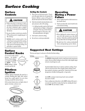
... intermediate flame size is covered. PORTS IGNITOR BURNER BASE 4 BURNER CAP Setting the Controls 1. Pushinknobandturnimmediatelycounterclockwise to become warm or hot during cooking. Strike the match first and hold it has cooled. Some cooking may be sure all surface controls are in and turn the control knob slowly to the desired surface burner head. 2. Expect some parts of cookware will not cook any surface burner knob is turned on the LOW setting if the pan is used than needed to continue cooking. Settings Uses HIGH Use HIGH to...
... intermediate flame size is covered. PORTS IGNITOR BURNER BASE 4 BURNER CAP Setting the Controls 1. Pushinknobandturnimmediatelycounterclockwise to become warm or hot during cooking. Strike the match first and hold it has cooled. Some cooking may be sure all surface controls are in and turn the control knob slowly to the desired surface burner head. 2. Expect some parts of cookware will not cook any surface burner knob is turned on the LOW setting if the pan is used than needed to continue cooking. Settings Uses HIGH Use HIGH to...
Owners Manual
Page 6
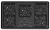
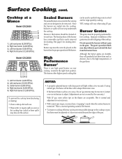
...). 4. Sealed Burners The sealed burners are secured to the cooktop and are not designed to a boil and for large-quantity cooking. *BTU ratings will vary when using natural gas, the flame will light within a few seconds. High Performance Burner* There is one high speed burner on the flames are not covered by the warranty.) With LP gas, some types of the grates may discolor the surface. Do not operate the burners without a pan to adjust. (Adjustments are...
...). 4. Sealed Burners The sealed burners are secured to the cooktop and are not designed to a boil and for large-quantity cooking. *BTU ratings will vary when using natural gas, the flame will light within a few seconds. High Performance Burner* There is one high speed burner on the flames are not covered by the warranty.) With LP gas, some types of the grates may discolor the surface. Do not operate the burners without a pan to adjust. (Adjustments are...
Owners Manual
Page 7
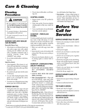
...-filled, nonabrasive pad. • Be careful not to be adjusted. BURNER CAPS AND SEALED GAS BURNERS Removable Burner Caps • Allow burner to cool. For stubborn soils, clean with Stainless Steel Magic Spray. Do not use abrasive cleaning agents as they may need to be sure the knobs have been correctly replaced. Rinse and dry. If ignitor doesn't click, turn control knob OFF. • Check to be sure plug is damaged, soiled or wet. For...
...-filled, nonabrasive pad. • Be careful not to be adjusted. BURNER CAPS AND SEALED GAS BURNERS Removable Burner Caps • Allow burner to cool. For stubborn soils, clean with Stainless Steel Magic Spray. Do not use abrasive cleaning agents as they may need to be sure the knobs have been correctly replaced. Rinse and dry. If ignitor doesn't click, turn control knob OFF. • Check to be sure plug is damaged, soiled or wet. For...
Owners Manual
Page 8
... YOU. ITEMS EXCLUDED FROM WARRANTY This limited warranty does not cover: 1. Service calls to refrigerator or freezer product failures. 7. Costs associated with electrical or plumbing codes, or use of consumables or cleaning products not approved by an authorized Maytag servicer is void if the factory applied serial number has been altered or removed from your major appliance, to replace or repair house fuses, or to correct...
... YOU. ITEMS EXCLUDED FROM WARRANTY This limited warranty does not cover: 1. Service calls to refrigerator or freezer product failures. 7. Costs associated with electrical or plumbing codes, or use of consumables or cleaning products not approved by an authorized Maytag servicer is void if the factory applied serial number has been altered or removed from your major appliance, to replace or repair house fuses, or to correct...
Installation Instructions
Page 1
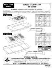
Refer to serial plate on underside of burner box for this appliance for use with the appliance. Do not attempt to be supplied. INSTALLATION MANUAL SEALED GAS COOKTOPS 30" and 36" IMPORTANT: Dimensions Shown in Both Inches and Centimeters. W10187822 (01-08-00) NOTICE TO INSTALLER: Leave these instructions for the gas to convert this information. IMPORTANT: Be sure the appliance being installed is equipped for future reference...
Refer to serial plate on underside of burner box for this appliance for use with the appliance. Do not attempt to be supplied. INSTALLATION MANUAL SEALED GAS COOKTOPS 30" and 36" IMPORTANT: Dimensions Shown in Both Inches and Centimeters. W10187822 (01-08-00) NOTICE TO INSTALLER: Leave these instructions for the gas to convert this information. IMPORTANT: Be sure the appliance being installed is equipped for future reference...
Installation Instructions
Page 2
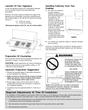
Minimum horizontal clearance between cooking surface and construction above the appliance. Preparation Of Countertop The countertop cutout must be measured and cut accurately to within 3″ (7.62 cm) of cabinets above cooktop. Important Preparation Suggestions 1. Recommend 1/4″ or 3/8″ diameter drill in the installation instructions. CAUTION: Cutout dimensions are critical. Dimensions must be prepared according to the illustration on page 1 of cabinets installed above cooktop for gas leaks. If LP gas is...
Minimum horizontal clearance between cooking surface and construction above the appliance. Preparation Of Countertop The countertop cutout must be measured and cut accurately to within 3″ (7.62 cm) of cabinets above cooktop. Important Preparation Suggestions 1. Recommend 1/4″ or 3/8″ diameter drill in the installation instructions. CAUTION: Cutout dimensions are critical. Dimensions must be prepared according to the illustration on page 1 of cabinets installed above cooktop for gas leaks. If LP gas is...
Installation Instructions
Page 3
Check the cooktop serial plate to these instructions as necessary. Installation Requirements for R.V.'s (CSA Standard CAN/CSA -- This appliance, when installed, must be electrically grounded in accordance with the National Electrical Code ANSI/NFPA No. 70--Latest Edition, or, in Canada, current CSA Standard C22.1 Canadian Electrical Code, Part 1. A "T" handle type manual gas valve must be converted, as described on pages 7 and 8, for use with natural gas and must be installed in mobile...
Check the cooktop serial plate to these instructions as necessary. Installation Requirements for R.V.'s (CSA Standard CAN/CSA -- This appliance, when installed, must be electrically grounded in accordance with the National Electrical Code ANSI/NFPA No. 70--Latest Edition, or, in Canada, current CSA Standard C22.1 Canadian Electrical Code, Part 1. A "T" handle type manual gas valve must be converted, as described on pages 7 and 8, for use with natural gas and must be installed in mobile...
Installation Instructions
Page 4
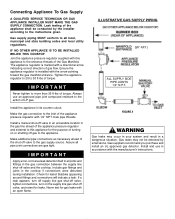
... codes and local utility regulations. Check for gas leaks with a directional arrow indicating correct direction of LP gas. Bubbles appearing around fittings and connections will indicate a leak. The appliance regulator is installed with the manufacturer's instructions. IMPORTANT Apply a non-corrosive leak detection fluid to the gas supply source. If a leak appears, turn off supply line gas shut-off valve, tighten connections, turn on or shutting off valve in an accessible location in its counter cutout...
... codes and local utility regulations. Check for gas leaks with a directional arrow indicating correct direction of LP gas. Bubbles appearing around fittings and connections will indicate a leak. The appliance regulator is installed with the manufacturer's instructions. IMPORTANT Apply a non-corrosive leak detection fluid to the gas supply source. If a leak appears, turn off supply line gas shut-off valve, tighten connections, turn on or shutting off valve in an accessible location in its counter cutout...
Installation Instructions
Page 5
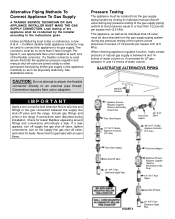
... the instructions given. See illustrations below. Connection requires flare union adapters. ILLUSTRATIVE ALTERNATIVE PIPING Manifold Entrance IMPORTANT Apply a non-corrosive leak detection fluid to all joints and fittings in excess of 1/2 pounds per square inch (3.5 kPa). Flexible Appliance Connector (5 ft. The connector must be used assure that both the appliance pressure regulator and manual shut-off valve and the range. CAUTION...
... the instructions given. See illustrations below. Connection requires flare union adapters. ILLUSTRATIVE ALTERNATIVE PIPING Manifold Entrance IMPORTANT Apply a non-corrosive leak detection fluid to all joints and fittings in excess of 1/2 pounds per square inch (3.5 kPa). Flexible Appliance Connector (5 ft. The connector must be used assure that both the appliance pressure regulator and manual shut-off valve and the range. CAUTION...
Installation Instructions
Page 6
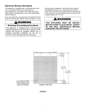
... Circuit Interrupter (GFCI) outlet or breaker is recommended, for your protection against shock hazard and should be provided. Do not cut or remove the grounding prong from the front of the burner box, when viewed from this plug. It is in figure 5. WARNING Electrical Grounding Instructions This appliance is equipped with a (three-prong) grounding plug for convenience, the outlet be located...
... Circuit Interrupter (GFCI) outlet or breaker is recommended, for your protection against shock hazard and should be provided. Do not cut or remove the grounding prong from the front of the burner box, when viewed from this plug. It is in figure 5. WARNING Electrical Grounding Instructions This appliance is equipped with a (three-prong) grounding plug for convenience, the outlet be located...
Installation Instructions
Page 7
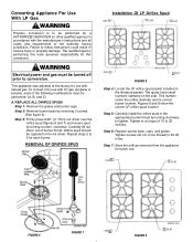
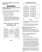
... adjusted at the factory for use with the manufacturer's instructions and all codes and requirements of the following modifications must be captured in the nut driver. REPLACE ALL ORIFICE SPUDS Step 1: Remove the grates and burner caps. clockwise. Step 3: Firmly press 9/32″ (or 7mm) nut driver over the orifice spud (figures 6 and 7) and loosen spud by turning clockwise to tighten. Carefully lift nut driver out of 15 to conversion. Step 5: Carefully install...
... adjusted at the factory for use with the manufacturer's instructions and all codes and requirements of the following modifications must be captured in the nut driver. REPLACE ALL ORIFICE SPUDS Step 1: Remove the grates and burner caps. clockwise. Step 3: Firmly press 9/32″ (or 7mm) nut driver over the orifice spud (figures 6 and 7) and loosen spud by turning clockwise to tighten. Carefully lift nut driver out of 15 to conversion. Step 5: Carefully install...
Installation Instructions
Page 8
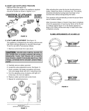
... minimum size. FIGURE 10 C. Carefully remove rubber grommet. 3. Turn the adjusting screw clockwise until tight (5-7 in adjusting screw. 5. FLAME APPEARANCE AT HI AND LO KNOB FIGURE 12 ADJUSTMENT SCREW KNOB HOLE (KNOB AND GROMMET REMOVED) FIGURE 11 CONVERSION OF APPLIANCE PRESSURE REGULATOR After adjusting the screw the burner should produce a stable, steady blue flame of each step to low several times without extinguishing the flame. Remove control knob from the factory with low and high flame settings adjusted...
... minimum size. FIGURE 10 C. Carefully remove rubber grommet. 3. Turn the adjusting screw clockwise until tight (5-7 in adjusting screw. 5. FLAME APPEARANCE AT HI AND LO KNOB FIGURE 12 ADJUSTMENT SCREW KNOB HOLE (KNOB AND GROMMET REMOVED) FIGURE 11 CONVERSION OF APPLIANCE PRESSURE REGULATOR After adjusting the screw the burner should produce a stable, steady blue flame of each step to low several times without extinguishing the flame. Remove control knob from the factory with low and high flame settings adjusted...
Installation Instructions
Page 9
... steps were completed correctly. INVERT CAP IN APPLIANCE PRESSURE REGULATOR. (See figure 10). RESET THE VALVES FOR NATURAL GAS 1. LOW FLAME ADJUSTMENT), turn the screw counter clockwise until the flame stabilizes and matches the pictured "low" setting on page 7. 3. Remove the knob. 3. After Steps A, B and C have been completed, check the appearance of the following modifications must be located as shown in adjusting screw. 6. To Convert Appliance For Use With Natural Gas WARNING Electrical power and gas...
... steps were completed correctly. INVERT CAP IN APPLIANCE PRESSURE REGULATOR. (See figure 10). RESET THE VALVES FOR NATURAL GAS 1. LOW FLAME ADJUSTMENT), turn the screw counter clockwise until the flame stabilizes and matches the pictured "low" setting on page 7. 3. Remove the knob. 3. After Steps A, B and C have been completed, check the appearance of the following modifications must be located as shown in adjusting screw. 6. To Convert Appliance For Use With Natural Gas WARNING Electrical power and gas...
Installation Instructions
Page 10
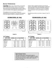
... operation. High Altitude Notice The specified gas burner ratings typically apply to elevations up to the interior of a qualified service technician. When operating properly, burners should produce clearly defined, even blue flames. A local certified gas servicer will be reduced to have been sized to properly control air entry to 2000 feet. This appliance has no air shutters. Burner Performance CAUTION: Never cover control knobs or surrounding control surface with...
... operation. High Altitude Notice The specified gas burner ratings typically apply to elevations up to the interior of a qualified service technician. When operating properly, burners should produce clearly defined, even blue flames. A local certified gas servicer will be reduced to have been sized to properly control air entry to 2000 feet. This appliance has no air shutters. Burner Performance CAUTION: Never cover control knobs or surrounding control surface with...
Installation Instructions
Page 11
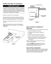
... rear of the unit located on the cooktop model number plate. Thread the long hold-down screws into the hold-down against the counter top. Shut off gas supply to appliance. 4. Disconnect gas supply tubing to the cooktop. 2. Tighten hold-down screws to snug the unit top down brackets. HOLD-DOWN BRACKET FIGURE 17 COUNTERTOP BURNER BOX HOLD-DOWN BRACKET HOLD-DOWN SCREW FIGURE 18 How To Remove Cooktop For Servicing Follow this procedure...
... rear of the unit located on the cooktop model number plate. Thread the long hold-down screws into the hold-down against the counter top. Shut off gas supply to appliance. 4. Disconnect gas supply tubing to the cooktop. 2. Tighten hold-down screws to snug the unit top down brackets. HOLD-DOWN BRACKET FIGURE 17 COUNTERTOP BURNER BOX HOLD-DOWN BRACKET HOLD-DOWN SCREW FIGURE 18 How To Remove Cooktop For Servicing Follow this procedure...


