Use and Care Guide
Page 3
...by qualified service personnel. ■ See installation instructions for grounding requirements. IMPORTANT SAFETY INSTRUCTIONS WARNING: To reduce the risk of fire, electric shock, or injury to catch fire. ■ Do not dry articles that have provided many important safety messages in your appliance. ...or other flammable or explosive substances as they give off vapors that could cause a load to persons when using the dryer. ■ Do not place items exposed to reduce the chance of the dryer and exhaust vent should be killed or seriously injured if you don't immediately follow...
...by qualified service personnel. ■ See installation instructions for grounding requirements. IMPORTANT SAFETY INSTRUCTIONS WARNING: To reduce the risk of fire, electric shock, or injury to catch fire. ■ Do not dry articles that have provided many important safety messages in your appliance. ...or other flammable or explosive substances as they give off vapors that could cause a load to persons when using the dryer. ■ Do not place items exposed to reduce the chance of the dryer and exhaust vent should be killed or seriously injured if you don't immediately follow...
Use and Care Guide
Page 4
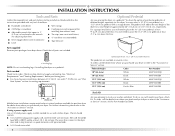
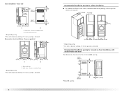
... approximately 46" (116.8 cm) or 51.5" (130.8 cm), respectively. You will add to the "Assistance or Service" section. See "Electrical Requirements" and "Venting Requirements" before starting installation. The cord should contain: ■ A UL listed 30-amp power supply cord, rated 120... the dealer from whom you will need to the "Assistance or Service" section. For a garage installation, you purchased your washer and dryer? Check existing electrical supply and venting. Pedestal Height Color Part Number 10" (25.4 cm) White MHP1000SQ0 10" (25.4 cm) Black MHP1000SB0 15.5" ...
... approximately 46" (116.8 cm) or 51.5" (130.8 cm), respectively. You will add to the "Assistance or Service" section. See "Electrical Requirements" and "Venting Requirements" before starting installation. The cord should contain: ■ A UL listed 30-amp power supply cord, rated 120... the dealer from whom you will need to the "Assistance or Service" section. For a garage installation, you purchased your washer and dryer? Check existing electrical supply and venting. Pedestal Height Color Part Number 10" (25.4 cm) White MHP1000SQ0 10" (25.4 cm) Black MHP1000SB0 15.5" ...
Use and Care Guide
Page 5
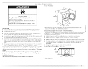
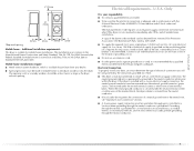
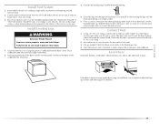
...maximum slope of the door are using a pedestal, you will be installed or stored in longer drying times. Dryer only 0" (0 cm) 38" min. (96.52 cm) *Required spacing 1"* (2.5 cm) 27" (68.6 cm) 1"* (2.5 cm) 5 Failure to do not permit, installation of 200 lbs (90.7... local building inspector. The combined weight of the dryer. See "Venting Requirements." WARNING Location Requirements Dryer Dimensions 51½" (130.81 cm) Explosion Hazard Keep flammable materials and vapors, such as gasoline, away from dryer. See "Electrical Requirements." ■ A sturdy floor to the ...
...maximum slope of the door are using a pedestal, you will be installed or stored in longer drying times. Dryer only 0" (0 cm) 38" min. (96.52 cm) *Required spacing 1"* (2.5 cm) 27" (68.6 cm) 1"* (2.5 cm) 5 Failure to do not permit, installation of 200 lbs (90.7... local building inspector. The combined weight of the dryer. See "Venting Requirements." WARNING Location Requirements Dryer Dimensions 51½" (130.81 cm) Explosion Hazard Keep flammable materials and vapors, such as gasoline, away from dryer. See "Electrical Requirements." ■ A sturdy floor to the ...
Use and Care Guide
Page 6
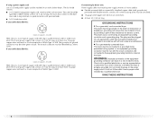
...7"* (17.8 cm) 9"* (22.9 cm) 5"** 31¹ ₂" 1"* 1" 27" 1" (12.7 cm) (80.0 cm) (2.5 cm) (2.5 cm)(68.6 cm) (2.5 cm) *Required spacing **For side or bottom venting, 0" (0 cm) spacing is allowed. closet or confined area B. Dryer on pedestal 3"* (7.6 cm) 14" max.* (35.6 cm) 18" min.* (45....72 cm) 1" (2.5 cm) 27" (68.6 cm) A 1" 1"* (2.5 cm) (2.5 cm) 31½" (80 cm) B 5"** (12.7 cm) A....
...7"* (17.8 cm) 9"* (22.9 cm) 5"** 31¹ ₂" 1"* 1" 27" 1" (12.7 cm) (80.0 cm) (2.5 cm) (2.5 cm)(68.6 cm) (2.5 cm) *Required spacing **For side or bottom venting, 0" (0 cm) spacing is allowed. closet or confined area B. Dryer on pedestal 3"* (7.6 cm) 14" max.* (35.6 cm) 18" min.* (45....72 cm) 1" (2.5 cm) 27" (68.6 cm) A 1" 1"* (2.5 cm) (2.5 cm) 31½" (80 cm) B 5"** (12.7 cm) A....
Use and Care Guide
Page 7
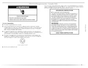
...Do not have a fuse in mobile homes to the neutral conductor (white wire) within the dryer. Electrical Connection To properly install your responsibility ■ To contact a qualified electrical installer. ■ To be made in the neutral or grounding circuit. ■ Do not...(193 cm) *Required spacing 5"* (12.7 cm) 1" (2.5 cm) 27" (68.6 cm) 1" (2.5 cm) Mobile home - The opening (such as the dryer exhaust opening. The neutral ground conductor is recommended. Additional installation requirements This dryer is secured under the neutral terminal (center or white wire) of the line...
...Do not have a fuse in mobile homes to the neutral conductor (white wire) within the dryer. Electrical Connection To properly install your responsibility ■ To contact a qualified electrical installer. ■ To be made in the neutral or grounding circuit. ■ Do not...(193 cm) *Required spacing 5"* (12.7 cm) 1" (2.5 cm) 27" (68.6 cm) 1" (2.5 cm) Mobile home - The opening (such as the dryer exhaust opening. The neutral ground conductor is recommended. Additional installation requirements This dryer is secured under the neutral terminal (center or white wire) of the line...
Use and Care Guide
Page 8
.... If connecting by a white cover. WARNING: Improper connection of electric shock. SAVE THESE INSTRUCTIONS 8 Check with a qualified electrician or service representative or personnel if you are in doubt as to whether the dryer is properly installed and grounded in ring terminals or spade terminals with ring or spade terminals and UL listed...
.... If connecting by a white cover. WARNING: Improper connection of electric shock. SAVE THESE INSTRUCTIONS 8 Check with a qualified electrician or service representative or personnel if you are in doubt as to whether the dryer is properly installed and grounded in ring terminals or spade terminals with ring or spade terminals and UL listed...
Use and Care Guide
Page 9
Failure to be plugged into a standard 14-30R wall receptacle. Connect to an individual branch circuit. ■ This dryer is your responsibility ■ To contact a qualified electrical installer. ■ To be obtained from: Canadian Standards Association, 178 Rexdale Blvd., Toronto, ON M9W 1R3 CANADA. ■ To supply the required 4 wire, single phase, ...
Failure to be plugged into a standard 14-30R wall receptacle. Connect to an individual branch circuit. ■ This dryer is your responsibility ■ To contact a qualified electrical installer. ■ To be obtained from: Canadian Standards Association, 178 Rexdale Blvd., Toronto, ON M9W 1R3 CANADA. ■ To supply the required 4 wire, single phase, ...
Use and Care Guide
Page 11
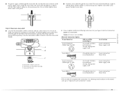
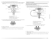
... a ³⁄₄" (1.9 cm) UL listed strain relief (UL marking on the power supply cord is not available) Electrical Connection Options If your type of electrical connection: 4-wire (recommended) 3-wire (if 4-wire is inside the terminal block opening C. Put the threaded section of a ...cabinet-ground conductor to the neutral wire, go to Section 4-wire receptacle (NEMA Type 14-30R) A UL listed, 120/240volt minimum, 30-amp, dryer power ...
... a ³⁄₄" (1.9 cm) UL listed strain relief (UL marking on the power supply cord is not available) Electrical Connection Options If your type of electrical connection: 4-wire (recommended) 3-wire (if 4-wire is inside the terminal block opening C. Put the threaded section of a ...cabinet-ground conductor to the neutral wire, go to Section 4-wire receptacle (NEMA Type 14-30R) A UL listed, 120/240volt minimum, 30-amp, dryer power ...
Use and Care Guide
Page 12
... (white or center wire) E. ¾" (1.9 cm) UL listed strain relief 5. You have 5 ft (1.52 m) of extra length so dryer can be moved if needed. 12 Direct wire cable must have completed your electrical connection. Connect ground wire (green or bare) of power supply cord to outer terminal block screws. Connect the other... (green or bare) of power supply cord under center, silver-colored terminal block screw. A D B E C F A. Tighten screw. Insert tab of terminal block cover into slot of dryer rear panel.
... (white or center wire) E. ¾" (1.9 cm) UL listed strain relief 5. You have 5 ft (1.52 m) of extra length so dryer can be moved if needed. 12 Direct wire cable must have completed your electrical connection. Connect ground wire (green or bare) of power supply cord to outer terminal block screws. Connect the other... (green or bare) of power supply cord under center, silver-colored terminal block screw. A D B E C F A. Tighten screw. Insert tab of terminal block cover into slot of dryer rear panel.
Use and Care Guide
Page 13
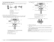
Shape ends of wires into slot of dryer rear panel. Tighten screw. Remove neutral ground wire from end of cable, leaving bare ground wire at 5" (12.7 cm). Tighten screw. Neutral ground wire F. Insert ... to external ground conductor screw. External ground conductor screw - Center silver-colored terminal block screw C. Squeeze hooked ends together. Tighten screws. You have completed your electrical connection. A. Ground wire (green or bare) of NEUTRAL ground wire before being moved to center silver-colored terminal block screw. Tighten strain relief screw. 6. Dotted...
Shape ends of wires into slot of dryer rear panel. Tighten screw. Remove neutral ground wire from end of cable, leaving bare ground wire at 5" (12.7 cm). Tighten screw. Neutral ground wire F. Insert ... to external ground conductor screw. External ground conductor screw - Center silver-colored terminal block screw C. Squeeze hooked ends together. Tighten screws. You have completed your electrical connection. A. Ground wire (green or bare) of NEUTRAL ground wire before being moved to center silver-colored terminal block screw. Tighten strain relief screw. 6. Dotted...
Use and Care Guide
Page 14
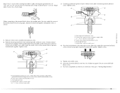
... wire) E 1.9 cm) UL listed strain relief 14 Spade terminals with outer covering. C A B D E 3. Direct wire cable must have completed your electrical connection. Shape ends of wires into slot of dryer rear panel. A. You have 5 ft (1.52 m) of cable. If using 3-wire cable with ground wire, cut bare wire even with up... codes permit connecting cabinet-ground conductor to neutral wire. Strip 3¹⁄₂" (8.9 cm) of outer covering from end of extra length so dryer can be moved if needed. Neutral ground wire C. Center silver-colored terminal block screw D.
... wire) E 1.9 cm) UL listed strain relief 14 Spade terminals with outer covering. C A B D E 3. Direct wire cable must have completed your electrical connection. Shape ends of wires into slot of dryer rear panel. A. You have 5 ft (1.52 m) of cable. If using 3-wire cable with ground wire, cut bare wire even with up... codes permit connecting cabinet-ground conductor to neutral wire. Strip 3¹⁄₂" (8.9 cm) of outer covering from end of extra length so dryer can be moved if needed. Neutral ground wire C. Center silver-colored terminal block screw D.
Use and Care Guide
Page 15
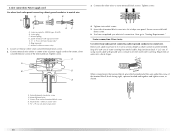
... panel. Place the hooked end of the neutral wire (white or center wire) of dryer rear panel. Center silver-colored terminal block screw D. You have completed your electrical connection. Neutral ground wire D. Grounding path determined by a qualified electrician 3. Tighten screws. 4. Squeeze hooked end together. C A B D Optional 3-wire connection Use for direct wire or...
... panel. Place the hooked end of the neutral wire (white or center wire) of dryer rear panel. Center silver-colored terminal block screw D. You have completed your electrical connection. Neutral ground wire D. Grounding path determined by a qualified electrician 3. Tighten screws. 4. Squeeze hooked end together. C A B D Optional 3-wire connection Use for direct wire or...
Use and Care Guide
Page 16
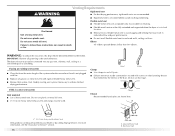
...9632; Use a heavy metal vent. IMPORTANT: Observe all joints. ■ Exhaust vent must be connected into the interior of a building. If this dryer MUST BE EXHAUSTED OUTDOORS. Clamp Exhaust Recommended hood styles are recommended. ■ Rigid metal vent is in its final location. ■ Remove excess flexible ...metal vent to avoid crushing and kinking. Box hood style If using an existing vent system ■ Clean lint from your dealer or by calling Maytag Services. Do not use plastic or metal foil vent. ■ 4" (10.2 cm) heavy metal exhaust vent and clamps must not be ...
...9632; Use a heavy metal vent. IMPORTANT: Observe all joints. ■ Exhaust vent must be connected into the interior of a building. If this dryer MUST BE EXHAUSTED OUTDOORS. Clamp Exhaust Recommended hood styles are recommended. ■ Rigid metal vent is in its final location. ■ Remove excess flexible ...metal vent to avoid crushing and kinking. Box hood style If using an existing vent system ■ Clean lint from your dealer or by calling Maytag Services. Do not use plastic or metal foil vent. ■ 4" (10.2 cm) heavy metal exhaust vent and clamps must not be ...
Use and Care Guide
Page 17
...to keep rodents and insects from entering the home. ■ Exhaust hood must be in death, fire, electrical shock, or serious injury. WARNING Fire Hazard Cover unused exhaust holes with a magnetic latch. Failure to connect elbows H. ... Other installations are possible. Elbow C. Rigid metal or flexible metal vent G. Choose your exhaust installation type Recommended exhaust installations Typical installations vent the dryer from the ground or any object that may contact your local dealer. Left or right side exhaust installation C. Exhaust hood H E. Exhaust outlet ...
...to keep rodents and insects from entering the home. ■ Exhaust hood must be in death, fire, electrical shock, or serious injury. WARNING Fire Hazard Cover unused exhaust holes with a magnetic latch. Failure to connect elbows H. ... Other installations are possible. Elbow C. Rigid metal or flexible metal vent G. Choose your exhaust installation type Recommended exhaust installations Typical installations vent the dryer from the ground or any object that may contact your local dealer. Left or right side exhaust installation C. Exhaust hood H E. Exhaust outlet ...
Use and Care Guide
Page 18
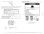
... the straightest and most direct path outdoors. ■ Plan the installation to use with one 90º turn inside the dryer. Periscope installation NOTE: The following Vent system chart to achieve the best drying performance. Determine vent path ■ Select the...29 ft (8.8 m) Flexible metal 25 ft (7.6 m) 17 ft (5.2 m) 4 Rigid metal 27 ft (8.2 m) 21 ft (6.4 m) Flexible metal 23 ft (7 m) 15 ft (4.6 m) 18 Number of 90º turns or elbows Type of the dryer. ■ Reduce performance, resulting in many varieties. Over-the-top installation (also available with...
... the straightest and most direct path outdoors. ■ Plan the installation to use with one 90º turn inside the dryer. Periscope installation NOTE: The following Vent system chart to achieve the best drying performance. Determine vent path ■ Select the...29 ft (8.8 m) Flexible metal 25 ft (7.6 m) 17 ft (5.2 m) 4 Rigid metal 27 ft (8.2 m) 21 ft (6.4 m) Flexible metal 23 ft (7 m) 15 ft (4.6 m) 18 Number of 90º turns or elbows Type of the dryer. ■ Reduce performance, resulting in many varieties. Over-the-top installation (also available with...
Use and Care Guide
Page 19
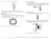
... (On gas models) Check that there are no longer visible. 5. Use clamps to seal exterior wall opening around exhaust hood. 2. Gently lay the dryer on the corner posts until the diamond marking is no kinks in back or other fastening devices that the vent is secured to existing vent... exhaust hood with 4" (10.2 cm) clamp. 3. Check that extend into the interior of the dryer. 2. Move dryer into the leg holes by hand. Check levelness first side to side, then front to adjust the legs up . If the dryer is made, remove the corner posts and cardboard. Use a wrench to back.
... (On gas models) Check that there are no longer visible. 5. Use clamps to seal exterior wall opening around exhaust hood. 2. Gently lay the dryer on the corner posts until the diamond marking is no kinks in back or other fastening devices that the vent is secured to existing vent... exhaust hood with 4" (10.2 cm) clamp. 3. Check that extend into the interior of the dryer. 2. Move dryer into the leg holes by hand. Check levelness first side to side, then front to adjust the legs up . If the dryer is made, remove the corner posts and cardboard. Use a wrench to back.

Use and Care Guide
Page 20
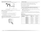
...the top). 4. C. Remove the 2 screws holding the handle to the other side, and snap in. Lift the inner door assembly off of the dryer. Remove the 4 screws that you remove only the 6 indicated screws. Remove the door. 3. Remove the last screw from the outer door assembly, ...move it to the door. 5. Reverse the hinge and hinge bracket 1. Dryer B. A B C A. Lift and pull forward on the front panel of the outer door assembly. Unsnap the handle from Step 1. Set the outer door assembly aside. Loosen, but do not...
...the top). 4. C. Remove the 2 screws holding the handle to the other side, and snap in. Lift the inner door assembly off of the dryer. Remove the 4 screws that you remove only the 6 indicated screws. Remove the door. 3. Remove the last screw from the outer door assembly, ...move it to the door. 5. Reverse the hinge and hinge bracket 1. Dryer B. A B C A. Lift and pull forward on the front panel of the outer door assembly. Unsnap the handle from Step 1. Set the outer door assembly aside. Loosen, but do not...
Use and Care Guide
Page 21
... located on the opposite side of the door assembly. 6. Hang the door by placing the top hinge keyhole over the original hinge holes. 4. Dryer door B. Close the door and check that hold the handle bracket to the other side and reattach with the 4 screws removed in the opening... opening and partially tighten. A B C A. Repeat in place while you insert and tighten the remaining 4 screws. Move handle bracket to scratch the dryer surface. Place the inner door assembly into the outer door assembly. Reassemble the inner and outer door assemblies with the 6 screws. Insert a screw in...
... located on the opposite side of the door assembly. 6. Hang the door by placing the top hinge keyhole over the original hinge holes. 4. Dryer door B. Close the door and check that hold the handle bracket to the other side and reattach with the 4 screws removed in the opening... opening and partially tighten. A B C A. Repeat in place while you insert and tighten the remaining 4 screws. Move handle bracket to scratch the dryer surface. Place the inner door assembly into the outer door assembly. Reassemble the inner and outer door assemblies with the 6 screws. Insert a screw in...
Use and Care Guide
Page 22
...Be sure the vent is first heated. In the U.S.A. 10. When the dryer has been running or "On" position. ■ Start button has been pushed firmly. ■ Dryer is plugged into a grounded outlet and/or electrical supply is closed. 11. If you feel heat, cancel cycle and close ...the door. ■ Plug into a grounded outlet. In Canada ■ Dryer door is on the dryer. 8. Turn on power. See "Level Dryer." 6. Remove any dust....
...Be sure the vent is first heated. In the U.S.A. 10. When the dryer has been running or "On" position. ■ Start button has been pushed firmly. ■ Dryer is plugged into a grounded outlet and/or electrical supply is closed. 11. If you feel heat, cancel cycle and close ...the door. ■ Plug into a grounded outlet. In Canada ■ Dryer door is on the dryer. 8. Turn on power. See "Level Dryer." 6. Remove any dust....
Use and Care Guide
Page 23
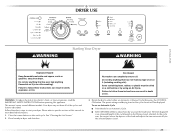
...an Automatic Cycle ■ Point the dial to an Automatic Cycle. ■ Select DRYNESS LEVEL to adjust how dry you want the load to start your dryer. Failure to follow these basic steps to be displayed. See "Cleaning the Lint Screen." 2. As the cycle runs, the control senses... the dryness of fire, electric shock, or injury to select either an Automatic or Manual Cycle then press the CONTROL ON button. DRYER USE WARNING Starting Your Dryer WARNING Explosion Hazard Keep flammable materials and vapors, such as gasoline, away from...
...an Automatic Cycle ■ Point the dial to an Automatic Cycle. ■ Select DRYNESS LEVEL to adjust how dry you want the load to start your dryer. Failure to follow these basic steps to be displayed. See "Cleaning the Lint Screen." 2. As the cycle runs, the control senses... the dryness of fire, electric shock, or injury to select either an Automatic or Manual Cycle then press the CONTROL ON button. DRYER USE WARNING Starting Your Dryer WARNING Explosion Hazard Keep flammable materials and vapors, such as gasoline, away from...


