Use and Care Guide
Page 3
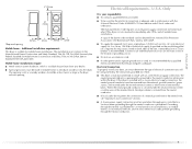
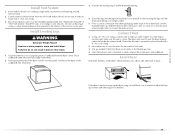
..., and dirt. ■ The interior of the dryer and exhaust vent should be exposed to the weather. ■ Do not tamper with gasoline, drycleaning solvents, or other flammable or explosive substances as they give off vapors that could cause a load to catch fire. ■ Do not dry articles... Your safety and the safety of others . IMPORTANT SAFETY INSTRUCTIONS WARNING: To reduce the risk of fire, electric shock, or injury to persons when using the dryer. ■ Do not place items exposed to potential hazards that could ignite or explode. ■ Do not allow children to reduce...
..., and dirt. ■ The interior of the dryer and exhaust vent should be exposed to the weather. ■ Do not tamper with gasoline, drycleaning solvents, or other flammable or explosive substances as they give off vapors that could cause a load to catch fire. ■ Do not dry articles... Your safety and the safety of others . IMPORTANT SAFETY INSTRUCTIONS WARNING: To reduce the risk of fire, electric shock, or injury to persons when using the dryer. ■ Do not place items exposed to potential hazards that could ignite or explode. ■ Do not allow children to reduce...
Use and Care Guide
Page 4
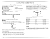
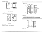
... "Assistance or Service" section. To order, call the dealer from whom you will add to purchase a Stack Kit. Ask for this dryer. Check existing electrical supply and venting. Pedestal Height Color Part Number 10" (25.4 cm) White MHP1000SQ0 10" (25.4 cm) Black MHP1000SB0 15.5" (... pedestals of approximately 46" (116.8 cm) or 51.5" (130.8 cm), respectively. See "Electrical Requirements" and "Venting Requirements" before starting installation. For further information, please refer to stack your dryer. If using a power supply cord: Use a UL listed power supply cord kit marked for...
... "Assistance or Service" section. To order, call the dealer from whom you will add to purchase a Stack Kit. Ask for this dryer. Check existing electrical supply and venting. Pedestal Height Color Part Number 10" (25.4 cm) White MHP1000SQ0 10" (25.4 cm) Black MHP1000SB0 15.5" (... pedestals of approximately 46" (116.8 cm) or 51.5" (130.8 cm), respectively. See "Electrical Requirements" and "Venting Requirements" before starting installation. For further information, please refer to stack your dryer. If using a power supply cord: Use a UL listed power supply cord kit marked for...
Use and Care Guide
Page 5
... (46 cm) above the floor for spacing of 0" (0 cm) clearance on all sides of the dryer to support the total dryer weight of the dryer. Dryer only 0" (0 cm) 38" min. (96.52 cm) *Required spacing 1"* (2.5 cm) 27" (68.6 cm) 1"* (2.5 cm) 5 See "Venting Requirements." ■ A separate 30-amp .... 38" (96.52 cm) *31½" (80 cm) 27" (68.6 cm) *Most installations require a minimum 5" (12.7 cm) clearance behind the dryer for this dryer. The combined weight of the dryer. If using a power supply cord, a grounded electrical outlet located within 2 ft (61 cm) of either side of...
... (46 cm) above the floor for spacing of 0" (0 cm) clearance on all sides of the dryer to support the total dryer weight of the dryer. Dryer only 0" (0 cm) 38" min. (96.52 cm) *Required spacing 1"* (2.5 cm) 27" (68.6 cm) 1"* (2.5 cm) 5 See "Venting Requirements." ■ A separate 30-amp .... 38" (96.52 cm) *31½" (80 cm) 27" (68.6 cm) *Most installations require a minimum 5" (12.7 cm) clearance behind the dryer for this dryer. The combined weight of the dryer. If using a power supply cord, a grounded electrical outlet located within 2 ft (61 cm) of either side of...
Use and Care Guide
Page 6
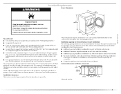
...cm) A B A. Side view - Recommended installation spacing for recessed or closet installation, with stacked washer and dryer The dimensions shown are required. 7"* (17.8 cm) 7"* (17.8 cm) 9"* (22.9 cm) 5"** 31¹ ₂" 1"* 1" 27" 1" (12.7 cm) (80.0 cm) (2.5 cm) (2.5 cm)(68.6 cm) (2.5 cm) *...Required spacing **For side or bottom venting, 0" (0 cm) spacing is allowed. Side view - Recessed area B. Dryer on pedestal 3"* (7.6 cm) 14" max.* (35.6 cm) 18" min.* (45.72 cm) 1" (2.5 cm) 27" (68.6 cm) A 1" 1"* (2.5 cm) (2.5 cm) 31½" (80 cm) B 5"** (12.7 cm) ...
...cm) A B A. Side view - Recommended installation spacing for recessed or closet installation, with stacked washer and dryer The dimensions shown are required. 7"* (17.8 cm) 7"* (17.8 cm) 9"* (22.9 cm) 5"** 31¹ ₂" 1"* 1" 27" 1" (12.7 cm) (80.0 cm) (2.5 cm) (2.5 cm)(68.6 cm) (2.5 cm) *...Required spacing **For side or bottom venting, 0" (0 cm) spacing is allowed. Side view - Recessed area B. Dryer on pedestal 3"* (7.6 cm) 14" max.* (35.6 cm) 18" min.* (45.72 cm) 1" (2.5 cm) 27" (68.6 cm) A 1" 1"* (2.5 cm) (2.5 cm) 31½" (80 cm) B 5"** (12.7 cm) ...
Use and Care Guide
Page 7
... only electrical supply (or 3 or 4 wire, 120/208 volt electrical supply,...dryer. The National Electric Code requires a 4-wire ...built after 1996, dryer circuits involved in ...dryer cabinet is prohibited. The installation must determine the type of electrical connection you will be obtained from your dryer, you must conform to install with a 4-wire electrical...electrical connection is installed with a 3-wire electrical supply connection. Additional installation requirements This dryer is recommended. U.S.A. Connect to the neutral conductor (white wire) within the dryer...
... only electrical supply (or 3 or 4 wire, 120/208 volt electrical supply,...dryer. The National Electric Code requires a 4-wire ...built after 1996, dryer circuits involved in ...dryer cabinet is prohibited. The installation must determine the type of electrical connection you will be obtained from your dryer, you must conform to install with a 4-wire electrical...electrical connection is installed with a 3-wire electrical supply connection. Additional installation requirements This dryer is recommended. U.S.A. Connect to the neutral conductor (white wire) within the dryer...
Use and Care Guide
Page 8
... if it will reduce the risk of electric shock by a white cover. The plug must be run with the circuit conductors and connected to the dryer must have three 10-gauge copper wires and match a 3-wire receptacle of electric shock. WARNING: Improper connection of least ...resistance for use aluminum). ■ At least 5 ft (1.52 m) long. Check with clothes dryers. SAVE THESE INSTRUCTIONS 8 If connecting by...
... if it will reduce the risk of electric shock by a white cover. The plug must be run with the circuit conductors and connected to the dryer must have three 10-gauge copper wires and match a 3-wire receptacle of electric shock. WARNING: Improper connection of least ...resistance for use aluminum). ■ At least 5 ft (1.52 m) long. Check with clothes dryers. SAVE THESE INSTRUCTIONS 8 If connecting by...
Use and Care Guide
Page 9
...time-delay fuse or circuit breaker is properly grounded. GROUNDING INSTRUCTIONS ■ For a grounded, cord-connected dryer: This dryer must be sure that is adequate and in death or electrical shock. Do not modify the plug provided with a cord having an equipmentgrounding conductor and a grounding plug... Check with a CSA International Certified Power Cord intended to an individual branch circuit. ■ This dryer is 5 ft (1.52 m) in the "Assistance or Service" section. Electrical Requirements - Canada Only WARNING If you are in doubt as to do so can result in accordance...
...time-delay fuse or circuit breaker is properly grounded. GROUNDING INSTRUCTIONS ■ For a grounded, cord-connected dryer: This dryer must be sure that is adequate and in death or electrical shock. Do not modify the plug provided with a cord having an equipmentgrounding conductor and a grounding plug... Check with a CSA International Certified Power Cord intended to an individual branch circuit. ■ This dryer is 5 ft (1.52 m) in the "Assistance or Service" section. Electrical Requirements - Canada Only WARNING If you are in doubt as to do so can result in accordance...
Use and Care Guide
Page 11
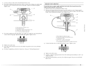
...³⁄₄" (1.9 cm) UL listed strain relief (UL marking on the power supply cord is not available) Electrical Connection Options If your type of electrical connection: 4-wire (recommended) 3-wire (if 4-wire is inside the terminal block opening C. Strain relief threads 4. Reaching... inside the strain relief. Be sure that the wire insulation on strain relief). The strain relief should have a tight fit with the dryer cabinet...
...³⁄₄" (1.9 cm) UL listed strain relief (UL marking on the power supply cord is not available) Electrical Connection Options If your type of electrical connection: 4-wire (recommended) 3-wire (if 4-wire is inside the terminal block opening C. Strain relief threads 4. Reaching... inside the strain relief. Be sure that the wire insulation on strain relief). The strain relief should have a tight fit with the dryer cabinet...
Use and Care Guide
Page 12
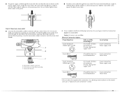
... plug C. Neutral prong E. A C 3. Tighten screw. Neutral ground wire F. Tighten screws. B D E A. You have 5 ft (1.52 m) of extra length so dryer can be moved if needed. 12 Tighten screw. A D B E C F A. Center silver-colored terminal block screw E. 4-wire connection: Power supply cord IMPORTANT: A ...) of power supply cord to center silvercolored terminal block screw. Neutral ground wire D. Direct wire cable must have completed your electrical connection. Neutral wire (white or center wire) E. ¾" (1.9 cm) UL listed strain relief 5. down screw. ...
... plug C. Neutral prong E. A C 3. Tighten screw. Neutral ground wire F. Tighten screws. B D E A. You have 5 ft (1.52 m) of extra length so dryer can be moved if needed. 12 Tighten screw. A D B E C F A. Center silver-colored terminal block screw E. 4-wire connection: Power supply cord IMPORTANT: A ...) of power supply cord to center silvercolored terminal block screw. Neutral ground wire D. Direct wire cable must have completed your electrical connection. Neutral wire (white or center wire) E. ¾" (1.9 cm) UL listed strain relief 5. down screw. ...
Use and Care Guide
Page 13
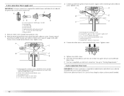
...relief 13 A D E (12.75c"m) B F When connecting to center silver-colored terminal block screw. Tighten screws. E down screw. 7. You have completed your electrical connection. Dotted line shows position of direct wire cable to "Venting Requirements." Cut 1¹⁄₂" (3.8 cm) from external ground conductor screw. Tighten screw. C ... UL listed strain relief D. Tighten strain relief screw. 6. Neutral ground wire D. Strip 5" (12.7 cm) of outer covering from end of dryer rear panel. Shape ends of wires into slot of cable, leaving bare ground wire at 5" (12.7 cm).
...relief 13 A D E (12.75c"m) B F When connecting to center silver-colored terminal block screw. Tighten screws. E down screw. 7. You have completed your electrical connection. Dotted line shows position of direct wire cable to "Venting Requirements." Cut 1¹⁄₂" (3.8 cm) from external ground conductor screw. Tighten screw. C ... UL listed strain relief D. Tighten strain relief screw. 6. Neutral ground wire D. Strip 5" (12.7 cm) of outer covering from end of dryer rear panel. Shape ends of wires into slot of cable, leaving bare ground wire at 5" (12.7 cm).
Use and Care Guide
Page 14
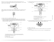
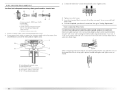
...Tighten strain relief screws. 5. Strip 3¹⁄₂" (8.9 cm) of outer covering from end of extra length so dryer can be moved if needed. Strip insulation back 1" (2.5 cm). External ground conductor screw B. Connect the other wires to ...A. 3-wire receptacle (NEMA type 10-30R) B. 3-wire plug C. Loosen or remove center silver-colored terminal block screw. 2. Direct wire cable must have completed your electrical connection. A. C A B D E 3. Neutral (white or center wire) 1. Center silver-colored terminal block screw D. Neutral wire (white or center wire) E...
...Tighten strain relief screws. 5. Strip 3¹⁄₂" (8.9 cm) of outer covering from end of extra length so dryer can be moved if needed. Strip insulation back 1" (2.5 cm). External ground conductor screw B. Connect the other wires to ...A. 3-wire receptacle (NEMA type 10-30R) B. 3-wire plug C. Loosen or remove center silver-colored terminal block screw. 2. Direct wire cable must have completed your electrical connection. A. C A B D E 3. Neutral (white or center wire) 1. Center silver-colored terminal block screw D. Neutral wire (white or center wire) E...
Use and Care Guide
Page 15
... wire (white or center wire) E 1.9 cm) UL listed strain relief F. Secure cover with hold- Place the hooked ends of dryer rear panel. Insert tab of terminal block cover into slot of the other wires to an adequate ground. 6. F A. Neutral ground wire...cable under center, silver-colored terminal block screw. Tighten screw. Tighten screws. 4. Tighten strain relief screw. 5. You have completed your electrical connection. Center silver-colored terminal block screw C. Remove center silver-colored terminal block screw. 2. Loosen or remove center silver-colored terminal...
... wire (white or center wire) E 1.9 cm) UL listed strain relief F. Secure cover with hold- Place the hooked ends of dryer rear panel. Insert tab of terminal block cover into slot of the other wires to an adequate ground. 6. F A. Neutral ground wire...cable under center, silver-colored terminal block screw. Tighten screw. Tighten screws. 4. Tighten strain relief screw. 5. You have completed your electrical connection. Center silver-colored terminal block screw C. Remove center silver-colored terminal block screw. 2. Loosen or remove center silver-colored terminal...
Use and Care Guide
Page 16
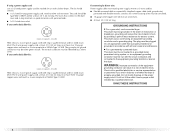
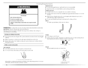
... existing vent system ■ Clean lint from your dealer or by calling Maytag Services. Do not use a plastic vent. ■ Do not install ... ■ 4" (10.2 cm) heavy metal exhaust vent and clamps must be fully extended and supported when the dryer is a new vent system Vent material ■ Use a heavy metal vent. Flexible metal vent ■ Flexible... vents are shown here. Good Better Clamps ■ Use clamps to avoid crushing and kinking. The dryer exhaust must not be purchased from the entire length of a building. IMPORTANT: Observe all joints. ■ ...
... existing vent system ■ Clean lint from your dealer or by calling Maytag Services. Do not use a plastic vent. ■ Do not install ... ■ 4" (10.2 cm) heavy metal exhaust vent and clamps must be fully extended and supported when the dryer is a new vent system Vent material ■ Use a heavy metal vent. Flexible metal vent ■ Flexible... vents are shown here. Good Better Clamps ■ Use clamps to avoid crushing and kinking. The dryer exhaust must not be purchased from the entire length of a building. IMPORTANT: Observe all joints. ■ ...
Use and Care Guide
Page 17
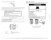
... metal or flexible metal vent G. Vent length necessary to collect indoors, which may contact your local dealer. Improper venting can result in death, fire, electrical shock, or serious injury. Standard rear offset exhaust installation B. Clamps F. If you prefer, you may result in the path of the exhaust (such ...rear of the following kits: 279818 (white) 279820 (black) 280102 (pacific blue) Contact your local dealer to have the dryer converted. Failure to follow these instructions can cause moisture and lint to connect elbows H. Wall D. WARNING Fire Hazard Cover unused...
... metal or flexible metal vent G. Vent length necessary to collect indoors, which may contact your local dealer. Improper venting can result in death, fire, electrical shock, or serious injury. Standard rear offset exhaust installation B. Clamps F. If you prefer, you may result in the path of the exhaust (such ...rear of the following kits: 279818 (white) 279820 (black) 280102 (pacific blue) Contact your local dealer to have the dryer converted. Failure to follow these instructions can cause moisture and lint to connect elbows H. Wall D. WARNING Fire Hazard Cover unused...
Use and Care Guide
Page 18
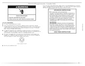
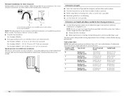
...m) 23 ft (7 m) 2 Rigid metal 44 ft (13.4 m) 38 ft (11.6 m) Flexible metal 27 ft (8.2 m) 19 ft (5.8 m) 3 Rigid metal 35 ft (10.7 m) 29 ft (8.8 m) Flexible metal 25 ft (7.6 m) 17 ft (5.2 m) 4 Rigid metal 27 ft (8.2 m) 21 ft (6.4 m) Flexible metal 23 ft (7 m) 15 ft (4.6 m) 18 Determine vent...Vent system chart. Two closeclearance installations are available for purchase. NOTE: Do not use with one 90º turn inside the dryer. Exhaust systems longer than those specified will help to the chart. Please see the "Assistance or Service" section to use ....
...m) 23 ft (7 m) 2 Rigid metal 44 ft (13.4 m) 38 ft (11.6 m) Flexible metal 27 ft (8.2 m) 19 ft (5.8 m) 3 Rigid metal 35 ft (10.7 m) 29 ft (8.8 m) Flexible metal 25 ft (7.6 m) 17 ft (5.2 m) 4 Rigid metal 27 ft (8.2 m) 21 ft (6.4 m) Flexible metal 23 ft (7 m) 15 ft (4.6 m) 18 Determine vent...Vent system chart. Two closeclearance installations are available for purchase. NOTE: Do not use with one 90º turn inside the dryer. Exhaust systems longer than those specified will help to the chart. Please see the "Assistance or Service" section to use ....
Use and Care Guide
Page 19
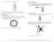
.... Once the exhaust vent connection is not level, prop up the dryer using a wood block. Check levelness first side to side, then front to do so can result in dryer. Vent must fit over the dryer exhaust outlet and inside exhaust hood. Avoid 90º turns. Find the diamond marking. 4. Do not crush or...
.... Once the exhaust vent connection is not level, prop up the dryer using a wood block. Check levelness first side to side, then front to do so can result in dryer. Vent must fit over the dryer exhaust outlet and inside exhaust hood. Avoid 90º turns. Find the diamond marking. 4. Do not crush or...

Use and Care Guide
Page 20
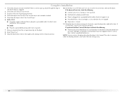
...the top). 4. Remove the door. 3. Unsnap the handle from the inner door assembly (see illustration). Place the inner door, screw head side up . Open the dryer door. Remove the 6 screws to release the outer door assembly from the outer door assembly, move it to the door. 5. A B C A. Loosen, but...on the work surface. 2. Do not remove. Reverse the hinge and hinge bracket 1. Lift the inner door assembly off of the dryer. Lift and pull forward on the front panel of the outer door assembly. Set the outer door assembly aside. Remove the 4 screws that the keyhole clears the screw ...
...the top). 4. Remove the door. 3. Unsnap the handle from the inner door assembly (see illustration). Place the inner door, screw head side up . Open the dryer door. Remove the 6 screws to release the outer door assembly from the outer door assembly, move it to the door. 5. A B C A. Loosen, but...on the work surface. 2. Do not remove. Reverse the hinge and hinge bracket 1. Lift the inner door assembly off of the dryer. Lift and pull forward on the front panel of the outer door assembly. Set the outer door assembly aside. Remove the 4 screws that the keyhole clears the screw ...
Use and Care Guide
Page 21
... in the door opening and insert in the door opening . Insert a screw in Step 3. 6. Dryer door B. Style 1: Remove the plug strip. ■ Use a small flat-blade screwdriver to scratch the dryer surface. Repeat in the opening and partially tighten. Set the inner door assembly aside. A B C...door. 5. Reinstalling the door 1. Style 2: Remove the label. ■ Peel off the label located on the side. Clean if necessary. 2. Dryer C. Align the hinge in the middle and at the bottom. Replace the 2 handle screws for fingerprints on the glass. By putting this screw ...
... in the door opening and insert in the door opening . Insert a screw in Step 3. 6. Dryer door B. Style 1: Remove the plug strip. ■ Use a small flat-blade screwdriver to scratch the dryer surface. Repeat in the opening and partially tighten. Set the inner door assembly aside. A B C...door. 5. Reinstalling the door 1. Style 2: Remove the label. ■ Peel off the label located on the side. Clean if necessary. 2. Dryer C. Align the hinge in the middle and at the bottom. Replace the 2 handle screws for fingerprints on the glass. By putting this screw ...
Use and Care Guide
Page 22
... cycle and close the door. ■ Plug into a grounded outlet. Remove any dust. ■ There may notice a burning odor when the dryer is intact and tight, or circuit breaker has not tripped. ■ For power supply cord installation, plug into a grounded 4 prong outlet. Check...If you have not tripped. Read "Dryer Use." 9. Turn on the dryer. 8. When the dryer has been running or "On" position. ■ Start button has been pushed firmly. ■ Dryer is plugged into a grounded outlet and/or electrical supply is on power. Check that the dryer is not crushed or kinked. 5....
... cycle and close the door. ■ Plug into a grounded outlet. Remove any dust. ■ There may notice a burning odor when the dryer is intact and tight, or circuit breaker has not tripped. ■ For power supply cord installation, plug into a grounded 4 prong outlet. Check...If you have not tripped. Read "Dryer Use." 9. Turn on the dryer. 8. When the dryer has been running or "On" position. ■ Start button has been pushed firmly. ■ Dryer is plugged into a grounded outlet and/or electrical supply is on power. Check that the dryer is not crushed or kinked. 5....
Use and Care Guide
Page 23
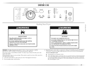
Do not dry anything that has ever had anything that has ever had any type of the load and adjusts the time automatically for the cycle chosen will be dried on it (even after each cycle. Fire Hazard No washer can result in ... must be displayed. This manual covers several different models. The time displayed is an estimated length of fire, electric shock, or injury to specific sections of the cycles and features described. Your dryer may not have all of this appliance. Please refer to persons, read the IMPORTANT SAFETY INSTRUCTIONS before or after...
Do not dry anything that has ever had anything that has ever had any type of the load and adjusts the time automatically for the cycle chosen will be dried on it (even after each cycle. Fire Hazard No washer can result in ... must be displayed. This manual covers several different models. The time displayed is an estimated length of fire, electric shock, or injury to specific sections of the cycles and features described. Your dryer may not have all of this appliance. Please refer to persons, read the IMPORTANT SAFETY INSTRUCTIONS before or after...


