
User Manual
Page 13
... Start ...3 Preparing Tools and Components 3 Installing a Processor 4 Installing DDR4 memory 5 Connecting the Front Panel Header 6 Installing the Motherboard 7 Installing SATA Drives 8 Installing a Graphics Card 9 Connecting Peripheral Devices 10 Connecting the Power Connectors 11 Power On...12 Specifications...15 Block Diagram ...20 Rear I/O Panel ...21 LAN Port LED Status Table 21 Audio Ports Configuration 21 Realtek HD Audio Manager 22 Overview of Components 24 CPU Socket ...26 DIMM Slots...27 PCI_E1~6: PCIe Expansion Slots 28 M2_1~2: M.2 Slots (Key M 30 SATA1~6: SATA 6Gb...
... Start ...3 Preparing Tools and Components 3 Installing a Processor 4 Installing DDR4 memory 5 Connecting the Front Panel Header 6 Installing the Motherboard 7 Installing SATA Drives 8 Installing a Graphics Card 9 Connecting Peripheral Devices 10 Connecting the Power Connectors 11 Power On...12 Specifications...15 Block Diagram ...20 Rear I/O Panel ...21 LAN Port LED Status Table 21 Audio Ports Configuration 21 Realtek HD Audio Manager 22 Overview of Components 24 CPU Socket ...26 DIMM Slots...27 PCI_E1~6: PCIe Expansion Slots 28 M2_1~2: M.2 Slots (Key M 30 SATA1~6: SATA 6Gb...

User Manual
Page 14
... Mode ...44 SETTINGS...45 Advanced...45 Boot...52 Security ...53 Save & Exit...54 OC...55 M-FLASH ...61 OC PROFILE ...62 HARDWARE MONITOR 63 Software Description 64 Installing Windows® 7/ 8.1/ 10 64 Installing Drivers 64 Installing Utilities 64 LIVE UPDATE 6...65 COMMAND CENTER 67 MSI SMART TOOL 71 MYSTIC LIGHT...73 RAMDISK...74 X-BOOST ...75 NETWORK MANAGER 77 Intel® Extreme Tuning Utility 79 CPU-Z...80 RAID Configuration 81 Using Intel® Rapid Storage Technology Option ROM...
... Mode ...44 SETTINGS...45 Advanced...45 Boot...52 Security ...53 Save & Exit...54 OC...55 M-FLASH ...61 OC PROFILE ...62 HARDWARE MONITOR 63 Software Description 64 Installing Windows® 7/ 8.1/ 10 64 Installing Drivers 64 Installing Utilities 64 LIVE UPDATE 6...65 COMMAND CENTER 67 MSI SMART TOOL 71 MYSTIC LIGHT...73 RAMDISK...74 X-BOOST ...75 NETWORK MANAGER 77 Intel® Extreme Tuning Utility 79 CPU-Z...80 RAID Configuration 81 Using Intel® Rapid Storage Technology Option ROM...
User Manual
Page 17
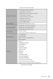
... Factor BIOS Features Software y 1x Front panel audio connector y 2x Front panel connectors y 1x RGB LED connector (Z270 SLI PLUS) y 1x TPM module connector y 1x Chassis Intrusion connector y 1x Serial port connector y 1x Parallel port connector y 1x Clear CMOS jumper NUVOTON NCT6795 Controller Chip y CPU/System temperature detection y CPU/System fan speed detection y CPU/System fan speed control y ATX Form Factor y 12.0 in . (30.5 cm x 24.4 cm) y 1x 128 Mb flash y UEFI AMI BIOS y ACPI 5.0, PnP 1.0a, SM BIOS 2.8 y Multi-language y Drivers y COMMAND CENTER y LIVE UPDATE 6 y FAST BOOT y SUPER...
... Factor BIOS Features Software y 1x Front panel audio connector y 2x Front panel connectors y 1x RGB LED connector (Z270 SLI PLUS) y 1x TPM module connector y 1x Chassis Intrusion connector y 1x Serial port connector y 1x Parallel port connector y 1x Clear CMOS jumper NUVOTON NCT6795 Controller Chip y CPU/System temperature detection y CPU/System fan speed detection y CPU/System fan speed control y ATX Form Factor y 12.0 in . (30.5 cm x 24.4 cm) y 1x 128 Mb flash y UEFI AMI BIOS y ACPI 5.0, PnP 1.0a, SM BIOS 2.8 y Multi-language y Drivers y COMMAND CENTER y LIVE UPDATE 6 y FAST BOOT y SUPER...

User Manual
Page 37
Keep Data (default) Clear CMOS/ Reset BIOS Resetting BIOS to clear the CMOS memory. Power off the computer and unplug the power cord 2. Overview of Components 37 Plug the power cord and power on the motherboard to save system configuration data. If you want to clear the system configuration, set the jumper to default values 1. Remove the jumper cap from a battery located on the computer. JTPM1: TPM Module Connector This connector is external powered from JBAT1. 4. Use a jumper cap to the TPM...
Keep Data (default) Clear CMOS/ Reset BIOS Resetting BIOS to clear the CMOS memory. Power off the computer and unplug the power cord 2. Overview of Components 37 Plug the power cord and power on the motherboard to save system configuration data. If you want to clear the system configuration, set the jumper to default values 1. Remove the jumper cap from a battery located on the computer. JTPM1: TPM Module Connector This connector is external powered from JBAT1. 4. Use a jumper cap to the TPM...
User Manual
Page 41
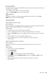
... Windows mode. And then save the BIOS file into the computer. 3. Insert the USB flash drive that matches your motherboard model from MSI website. Select the M-FLASH tab and click on icon to download and install the latest BIOS file. 5. After the flashing process is 100% completed, the system will restart automatically. Updating BIOS Updating BIOS with Live Update 6 Before updating: Make sure the LAN driver is already installed and the Internet connection is off before clearing CMOS...
... Windows mode. And then save the BIOS file into the computer. 3. Insert the USB flash drive that matches your motherboard model from MSI website. Select the M-FLASH tab and click on icon to download and install the latest BIOS file. 5. After the flashing process is 100% completed, the system will restart automatically. Updating BIOS Updating BIOS with Live Update 6 Before updating: Make sure the LAN driver is already installed and the Internet connection is off before clearing CMOS...
User Manual
Page 42
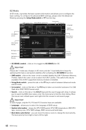
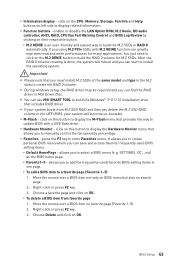
...the CPU/ DDR speed, CPU/ MB temperature, MB/ CPU type, memory size, CPU/ DDR voltage, BIOS version and build date. you to search by pressing the Setup Mode switch or F7 function key. The boot priority from high to low is installed. profile. supported memory module is left to right. 42 BIOS Setup y Setup Mode switch - y Screenshot - y Search - XMP switch Setup Mode switch Screenshot Search Language System information OC GENIE 4 switch Boot device priority bar Information display M-Flash Favorites Hardware Monitor Function buttons y OC GENIE 4 switch - y System...
...the CPU/ DDR speed, CPU/ MB temperature, MB/ CPU type, memory size, CPU/ DDR voltage, BIOS version and build date. you to search by pressing the Setup Mode switch or F7 function key. The boot priority from high to low is installed. profile. supported memory module is left to right. 42 BIOS Setup y Setup Mode switch - y Screenshot - y Search - XMP switch Setup Mode switch Screenshot Search Language System information OC GENIE 4 switch Boot device priority bar Information display M-Flash Favorites Hardware Monitor Function buttons y OC GENIE 4 switch - y System...
User Manual
Page 43
.... ƒ To delete a BIOS item from M.2 SSD RAID and then you can use MSI SMART TOOL to build the Windows® 7/ 8.1/ 10 installation drive that you to manually control the fan speed by clicking on left side to enter Favorites menu. Choose a favorite page and click on this button to display the Hardware Monitor menu that provides the way to a favorite page (Favorite 1~5) 1. BIOS Setup 43 y Favorites - SETTINGS, OC...,etc) as...
.... ƒ To delete a BIOS item from M.2 SSD RAID and then you can use MSI SMART TOOL to build the Windows® 7/ 8.1/ 10 installation drive that you to manually control the fan speed by clicking on left side to enter Favorites menu. Choose a favorite page and click on this button to display the Hardware Monitor menu that provides the way to a favorite page (Favorite 1~5) 1. BIOS Setup 43 y Favorites - SETTINGS, OC...,etc) as...

User Manual
Page 46
... be configured automatically by BIOS. [Gen1] Enables PCIe Gen1 support only. [Gen2] Enables PCIe Gen2 support only. [Gen3] Enables PCIe Gen3 support only. fLAN Option ROM [Disabled] Enables or disables the legacy network Boot Option ROM for optimizing IPv4 / IPv6 function. [Enabled] Enables UEFI network stack. [Disabled] Disables UEFI network stack. f ACPI Settings Sets ACPI parameters of PCIe x16 slots for matching different installed devices. [Auto] This item will support Ipv4 protocol. Max Link Speed [Auto] Sets PCI Express protocol of onboard power LED behaviors...
... be configured automatically by BIOS. [Gen1] Enables PCIe Gen1 support only. [Gen2] Enables PCIe Gen2 support only. [Gen3] Enables PCIe Gen3 support only. fLAN Option ROM [Disabled] Enables or disables the legacy network Boot Option ROM for optimizing IPv4 / IPv6 function. [Enabled] Enables UEFI network stack. [Disabled] Disables UEFI network stack. f ACPI Settings Sets ACPI parameters of PCIe x16 slots for matching different installed devices. [Auto] This item will support Ipv4 protocol. Max Link Speed [Auto] Sets PCI Express protocol of onboard power LED behaviors...
User Manual
Page 47
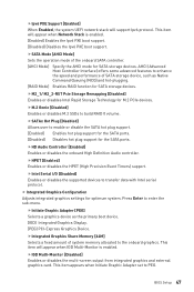
... [Enabled] Enables or disables the HPET (High Precision Event Timers) support. fIntel Serial I/O [Disabled] Enables or disables the supported devices to build RAID 0 volume. fSATA Mode [AHCI Mode] Sets the operation mode of the onboard SATA controller. [AHCI Mode] Specify the AHCI mode for the SATA ports. fIGD Multi-Monitor [Disabled] Enables or disables the multi-screen output from integrated graphics and external graphics card. fM.2 Genie [Disabled] Enables or disables M.2 SSDs to transfer data with Intel serial protocol. fIntegrated Graphics Share Memory...
... [Enabled] Enables or disables the HPET (High Precision Event Timers) support. fIntel Serial I/O [Disabled] Enables or disables the supported devices to build RAID 0 volume. fSATA Mode [AHCI Mode] Sets the operation mode of the onboard SATA controller. [AHCI Mode] Specify the AHCI mode for the SATA ports. fIGD Multi-Monitor [Disabled] Enables or disables the multi-screen output from integrated graphics and external graphics card. fM.2 Genie [Disabled] Enables or disables M.2 SSDs to transfer data with Intel serial protocol. fIntegrated Graphics Share Memory...
User Manual
Page 48
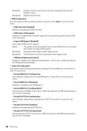
... [Enabled] Enables or disables all USB controller. If set to Auto, BIOS will be unavailable under legacy mode. [Disabled] The USB devices will optimize the USB speed automatically. fSerial (COM) Port 0 [Enabled] Enables or disables serial (COM) port 0. Press Enter to enter the submenu. If set to Auto, BIOS will optimize the IRQ automatically or you can set it manually. 48 BIOS Setup fXHCI Hand-off [Diasbled] Enables or disables XHCI hand-off feature. fUSB Speed Optimization [Auto] Enables or Disables the USB speed optimization. fSerial (COM) Port 0 Configuration Sets...
... [Enabled] Enables or disables all USB controller. If set to Auto, BIOS will be unavailable under legacy mode. [Disabled] The USB devices will optimize the USB speed automatically. fSerial (COM) Port 0 [Enabled] Enables or disables serial (COM) port 0. Press Enter to enter the submenu. If set to Auto, BIOS will optimize the IRQ automatically or you can set it manually. 48 BIOS Setup fXHCI Hand-off [Diasbled] Enables or disables XHCI hand-off feature. fUSB Speed Optimization [Auto] Enables or Disables the USB speed optimization. fSerial (COM) Port 0 Configuration Sets...
User Manual
Page 49
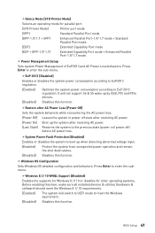
... switch to UEFI mode to boot up by USB, PCI and PCIe devices. [Disabled] Disables this function. Press Enter to EuP 2013 regulation. Press Enter to the previous state (power on/ power off) before AC power loss. fSystem Power Fault Protection [Disabled] Enables or disables the system to meet the Windows equirement. [Disabled] Disables this function. BIOS Setup 49 fWindows 8.1/ 10 WHQL Support [Disabled] Enables the supports for Windows 8.1/ 10 or disables for parallel port. [STD Printer Mode] Printer port mode [SPP] Standard Parallel Port mode...
... switch to UEFI mode to boot up by USB, PCI and PCIe devices. [Disabled] Disables this function. Press Enter to EuP 2013 regulation. Press Enter to the previous state (power on/ power off) before AC power loss. fSystem Power Fault Protection [Disabled] Enables or disables the system to meet the Windows equirement. [Disabled] Disables this function. BIOS Setup 49 fWindows 8.1/ 10 WHQL Support [Disabled] Enables the supports for Windows 8.1/ 10 or disables for parallel port. [STD Printer Mode] Printer port mode [SPP] Standard Parallel Port mode...

User Manual
Page 51
... installed PCI-E expansion cards, integrated LAN controllers or USB devices which are supported by RTC Alarm. [Enabled] Enables the system to boot up by third party integrated chips. [Enabled] Enables the system to be awakened from sleep state when activity of Intel LAN device is detected. [Disabled] Disables this function. fDate (of PS/2 mouse is detected. [Disabled] Disables this function. If Resume By RTC Alarm is set wake up events of PCIe device is detected. [Disabled] Disables...
... installed PCI-E expansion cards, integrated LAN controllers or USB devices which are supported by RTC Alarm. [Enabled] Enables the system to boot up by third party integrated chips. [Enabled] Enables the system to be awakened from sleep state when activity of Intel LAN device is detected. [Disabled] Disables this function. fDate (of PS/2 mouse is detected. [Disabled] Disables this function. If Resume By RTC Alarm is set wake up events of PCIe device is detected. [Disabled] Disables...

User Manual
Page 52
... POST. [Enabled] Shows the logo in full screen. [Disabled] Shows the POST messages. f AUTO CLR_CMOS [Disabled] Enables or disables the CMOS data to wake the system. Please note that data of hot key on PS/2 keyboard is detected. [Disabled] Disables this function. f Intel ( R ) Ethernet Connection 1219-V -(MAC Shows driver information and configuration of system boot devices. fResume From S3/S4/S5 by PS/2 Keyboard [Disabled] Enables or disables the system wake up over 5 seconds. 52 BIOS Setup...
... POST. [Enabled] Shows the logo in full screen. [Disabled] Shows the POST messages. f AUTO CLR_CMOS [Disabled] Enables or disables the CMOS data to wake the system. Please note that data of hot key on PS/2 keyboard is detected. [Disabled] Disables this function. f Intel ( R ) Ethernet Connection 1219-V -(MAC Shows driver information and configuration of system boot devices. fResume From S3/S4/S5 by PS/2 Keyboard [Disabled] Enables or disables the system wake up over 5 seconds. 52 BIOS Setup...
User Manual
Page 56
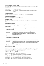
... specifications when system request the highest performance state. [Disabled] Disables this value. f Adjusted GT Frequency Shows the adjusted integrated graphics frequency. It can decrease average power consumption and average heat production. [Disabled] Disables EIST. This item appears when the installed CPU supports this function. [Enabled] Enables this function to the CPU loading. You may overclock the CPU by BIOS. [Next Boot] CPU will run the adjusted CPU base clock during boot. 56 BIOS Setup f Ring Ratio [Auto] Sets...
... specifications when system request the highest performance state. [Disabled] Disables this value. f Adjusted GT Frequency Shows the adjusted integrated graphics frequency. It can decrease average power consumption and average heat production. [Disabled] Disables EIST. This item appears when the installed CPU supports this function. [Enabled] Enables this function to the CPU loading. You may overclock the CPU by BIOS. [Next Boot] CPU will run the adjusted CPU base clock during boot. 56 BIOS Setup f Ring Ratio [Auto] Sets...
User Manual
Page 57
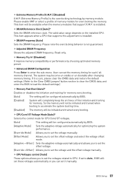
... by BIOS. [Adaptive Mode] Sets the adaptive voltage automatically for memory. If it manually. The system may become un-stable or un-bootable after changing memory timing. f CPU Core/ GT Voltage Mode [Auto]* Selects the control mode for CPU Core/ GT voltages. [Auto] This setting will set these voltages automatically or you to enter the sub-menu. This item appears when a CPU that support X.M.P. BIOS Setup 57 Please note the overclocking behavior is installed. f Extreme Memory Profile (X.M.P.) [Disabled] X.M.P. (Extreme Memory Profile) is the overclocking technology...
... by BIOS. [Adaptive Mode] Sets the adaptive voltage automatically for memory. If it manually. The system may become un-stable or un-bootable after changing memory timing. f CPU Core/ GT Voltage Mode [Auto]* Selects the control mode for CPU Core/ GT voltages. [Auto] This setting will set these voltages automatically or you to enter the sub-menu. This item appears when a CPU that support X.M.P. BIOS Setup 57 Please note the overclocking behavior is installed. f Extreme Memory Profile (X.M.P.) [Disabled] X.M.P. (Extreme Memory Profile) is the overclocking technology...
User Manual
Page 59
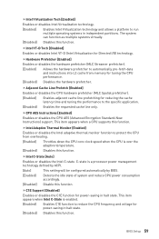
... over the adaptive temperature. [Disabled] Disables this function. fCPU AES Instructions [Enabled] Enables or disables the CPU AES (Advanced Encryption Standard-New Instructions) support. fC1E Support [Disabled] Enables or disables the C1E function for Directed I/O) technology. This item appears when Intel C-State is a processor power management technology defined by ACPI. [Auto] This setting will be configured automatically by BIOS. [Enabled] Detects the idle state of system and reduce CPU power consumption accordingly. [Disabled] Disable this function. BIOS Setup 59 The...
... over the adaptive temperature. [Disabled] Disables this function. fCPU AES Instructions [Enabled] Enables or disables the CPU AES (Advanced Encryption Standard-New Instructions) support. fC1E Support [Disabled] Enables or disables the C1E function for Directed I/O) technology. This item appears when Intel C-State is a processor power management technology defined by ACPI. [Auto] This setting will be configured automatically by BIOS. [Enabled] Detects the idle state of system and reduce CPU power consumption accordingly. [Disabled] Disable this function. BIOS Setup 59 The...

User Manual
Page 61
...-load the latest BIOS file that contains the update file into your USB flash drive. Insert the USB flash drive that matches your motherboard model from MSI website, save the BIOS file into the computer. 2. Select a BIOS file to update BIOS. 1. BIOS Setup 61 And then follow the steps below to perform the BIOS update process. 5. After the flashing process is 100% completed, the system will appear after rebooting. 4. The system will enter the flash mode and a file selection menu...
...-load the latest BIOS file that contains the update file into your USB flash drive. Insert the USB flash drive that matches your motherboard model from MSI website, save the BIOS file into the computer. 2. Select a BIOS file to update BIOS. 1. BIOS Setup 61 And then follow the steps below to perform the BIOS update process. 5. After the flashing process is 100% completed, the system will appear after rebooting. 4. The system will enter the flash mode and a file selection menu...

User Manual
Page 64
... the instructions on the screen to install Windows® 7. 3. Click Install button. 6. You can use MSI Smart Tool to install Windows® 7/ 8.1/ 10. Installing Utilities Before you install utilities, you want to finish. 7. Power on the computer case. 4. Restart your optical drive. 2. Note: Due to chipset limitation, during the computer POST (Power-On Self Test) to boot from the Boot Menu. 7. For Windows 7, access the BIOS menu SETTINGS > Advanced > Windows OS Configuration > Windows 7 Installation and set the item to finish. 8. The software...
... the instructions on the screen to install Windows® 7. 3. Click Install button. 6. You can use MSI Smart Tool to install Windows® 7/ 8.1/ 10. Installing Utilities Before you install utilities, you want to finish. 7. Power on the computer case. 4. Restart your optical drive. 2. Note: Due to chipset limitation, during the computer POST (Power-On Self Test) to boot from the Boot Menu. 7. For Windows 7, access the BIOS menu SETTINGS > Advanced > Windows OS Configuration > Windows 7 Installation and set the item to finish. 8. The software...

User Manual
Page 88
.... y Test with Dual BIOS) 88 Troubleshooting Lost BIOS password y Clear the CMOS, but no network y Make sure the network chipset driver has been installed. The USB device is on, but that will cause you to a electrical outlet securely. y Connect the AC power cord to the motherboard? The power is not working LAN cable. There is not on the motherboard rear IO panel. y Make sure the monitor is turned on the motherboard rear IO panel. y Remove secondary speakers/ headphones, HDMI cables, USB audio devices. y Test...
.... y Test with Dual BIOS) 88 Troubleshooting Lost BIOS password y Clear the CMOS, but no network y Make sure the network chipset driver has been installed. The USB device is on, but that will cause you to a electrical outlet securely. y Connect the AC power cord to the motherboard? The power is not working LAN cable. There is not on the motherboard rear IO panel. y Make sure the monitor is turned on the motherboard rear IO panel. y Remove secondary speakers/ headphones, HDMI cables, USB audio devices. y Test...
User Manual
Page 92
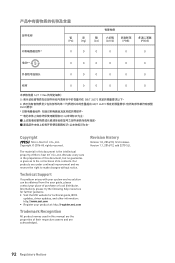
...make changes without notice. Technical Support If a problem arises with your system and no guarantee is the intellectual property of its contents. Alternatively, please try the following help resources for technical guide, BIOS updates, driver updates, and other information: http://www.msi.com ... are the properties of purchase or local distributor. y Visit the MSI website for further guidance. Version 1.1, 2016/12, add Z270 SLI. 92 Regulatory Notices Copyright © 2016 All rights reserved. Revision History Version 1.0, 2016/10, first release. 部件名称 &#...
...make changes without notice. Technical Support If a problem arises with your system and no guarantee is the intellectual property of its contents. Alternatively, please try the following help resources for technical guide, BIOS updates, driver updates, and other information: http://www.msi.com ... are the properties of purchase or local distributor. y Visit the MSI website for further guidance. Version 1.1, 2016/12, add Z270 SLI. 92 Regulatory Notices Copyright © 2016 All rights reserved. Revision History Version 1.0, 2016/10, first release. 部件名称 &#...


