
User Manual
Page 13
... Quick Start ...3 Preparing Tools and Components 3 Installing a Processor 4 Installing DDR4 memory 5 Connecting the Front Panel Header 6 Installing the Motherboard 7 Installing SATA Drives 8 Installing a Graphics Card 9 Connecting Peripheral Devices 10 Connecting the Power Connectors 11 Power On...12 Specifications...15 Specification Comparison Table 20 Block Diagram ...21 Rear I/O Panel ...22 LAN Port LED Status Table 22 Realtek HD Audio Manager 22 Overview of Components 24 CPU Socket ...26 DIMM Slots...27 PCI_E1~5, PCI1: PCIe/ PCI Expansion Slots 28 M2_1~2: M.2 Slots (Key M 29...
... Quick Start ...3 Preparing Tools and Components 3 Installing a Processor 4 Installing DDR4 memory 5 Connecting the Front Panel Header 6 Installing the Motherboard 7 Installing SATA Drives 8 Installing a Graphics Card 9 Connecting Peripheral Devices 10 Connecting the Power Connectors 11 Power On...12 Specifications...15 Specification Comparison Table 20 Block Diagram ...21 Rear I/O Panel ...22 LAN Port LED Status Table 22 Realtek HD Audio Manager 22 Overview of Components 24 CPU Socket ...26 DIMM Slots...27 PCI_E1~5, PCI1: PCIe/ PCI Expansion Slots 28 M2_1~2: M.2 Slots (Key M 29...

User Manual
Page 36
... Ground JBAT1: Clear CMOS (Reset BIOS) Jumper There is CMOS memory onboard that is external powered from JBAT1. 4. Please refer to the TPM security platform manual for TPM (Trusted Platform Module). If you want to clear the system configuration, set the jumper to short JBAT1 for about 5-10 seconds. 3. Use a jumper cap to clear the CMOS memory. Plug the power cord and power on the motherboard to default values 1. Remove the jumper cap from a battery located on the computer...
... Ground JBAT1: Clear CMOS (Reset BIOS) Jumper There is CMOS memory onboard that is external powered from JBAT1. 4. Please refer to the TPM security platform manual for TPM (Trusted Platform Module). If you want to clear the system configuration, set the jumper to short JBAT1 for about 5-10 seconds. 3. Use a jumper cap to clear the CMOS memory. Plug the power cord and power on the motherboard to default values 1. Remove the jumper cap from a battery located on the computer...
User Manual
Page 40
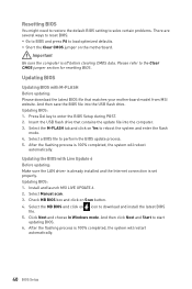
... BIOS file into the computer. 3. Insert the USB flash drive that matches your motherboard model from MSI website. Updating the BIOS with M-FLASH Before updating: Please download the latest BIOS file that contains the update file into the USB flash drive. Select the MB BIOS and click on the motherboard. y Short the Clear CMOS jumper on icon to download and install the latest BIOS file. 5. Install and launch MSI LIVE UPDATE 6. 2. Click Next and choose In Windows mode. Select the M-FLASH tab and click on Scan button. 4. Updating BIOS...
... BIOS file into the computer. 3. Insert the USB flash drive that matches your motherboard model from MSI website. Updating the BIOS with M-FLASH Before updating: Please download the latest BIOS file that contains the update file into the USB flash drive. Select the MB BIOS and click on the motherboard. y Short the Clear CMOS jumper on icon to download and install the latest BIOS file. 5. Install and launch MSI LIVE UPDATE 6. 2. Click Next and choose In Windows mode. Select the M-FLASH tab and click on Scan button. 4. Updating BIOS...

User Manual
Page 41
... to select the language of BIOS setup. The boot priority from high to low is installed. Important Please don't make any changes in OC menu and don't load defaults to right. y Screenshot - It allows you to exit search page. To configure the advanced BIOS settings, please enter the Advanced Mode by BIOS item name, enter the item name to enable/ disable the X.M.P. (Extreme Memory Profile). supported memory module is left to...
... to select the language of BIOS setup. The boot priority from high to low is installed. Important Please don't make any changes in OC menu and don't load defaults to right. y Screenshot - It allows you to exit search page. To configure the advanced BIOS settings, please enter the Advanced Mode by BIOS item name, enter the item name to enable/ disable the X.M.P. (Extreme Memory Profile). supported memory module is left to...
User Manual
Page 42
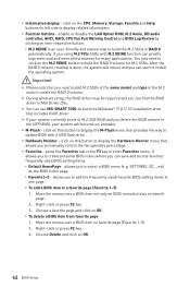
... way to display the M-Flash menu that includes RAID driver. y Hardware Monitor - allows you can greatly improves read and write performances for M.2 SSDs. y Information display - enable or disable the LAN Option ROM, M.2 Genie, HD audio controller, AHCI, RAID, CPU Fan Fail Warning Control and BIOS Log Review by percentage. You just need to click on this button to build the M.2 SSDs in MSI Driver Disc. y You can use MSI SMART TOOL to build the Windows® 7/ 8.1/ 10 installation drive that...
... way to display the M-Flash menu that includes RAID driver. y Hardware Monitor - allows you can greatly improves read and write performances for M.2 SSDs. y Information display - enable or disable the LAN Option ROM, M.2 Genie, HD audio controller, AHCI, RAID, CPU Fan Fail Warning Control and BIOS Log Review by percentage. You just need to click on this button to build the M.2 SSDs in MSI Driver Disc. y You can use MSI SMART TOOL to build the Windows® 7/ 8.1/ 10 installation drive that...
User Manual
Page 45
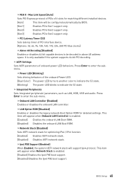
...Press Enter to enter the sub-menu. fPEG X - Max Link Speed [Auto] Sets PCI Express protocol of the onboard Power LED. [Dual Color] The power LED turns to another color to indicate the S3 state. [Blinking] The power LED blinks to be configured automatically by BIOS. [Gen1] Enables PCIe Gen1 support only. [Gen2] Enables PCIe Gen2 support only. [Gen3] Enables PCIe Gen3 support only. fLAN Option ROM [Disabled] Enables or disables the legacy network Boot Option ROM for optimizing IPv4 / IPv6 function. [Enabled] Enables UEFI network stack. [Disabled] Disables UEFI network...
...Press Enter to enter the sub-menu. fPEG X - Max Link Speed [Auto] Sets PCI Express protocol of the onboard Power LED. [Dual Color] The power LED turns to another color to indicate the S3 state. [Blinking] The power LED blinks to be configured automatically by BIOS. [Gen1] Enables PCIe Gen1 support only. [Gen2] Enables PCIe Gen2 support only. [Gen3] Enables PCIe Gen3 support only. fLAN Option ROM [Disabled] Enables or disables the legacy network Boot Option ROM for optimizing IPv4 / IPv6 function. [Enabled] Enables UEFI network stack. [Disabled] Disables UEFI network...

User Manual
Page 46
...Enter to the onboard graphics. fHD Audio Controller [Enabled] Enables or disables the onboard High Definition Audio controller. fInitiate Graphic Adapter [PEG] Selects a graphics device as Native Command Queuing (NCQ) and hot-plugging. [RAID Mode] Enables RAID function for SATA storage devices. fIGD Multi-Monitor [Disabled] Enables or disables the multi-screen output from integrated graphics and external graphics card. fM2_1/ M2_2-RST Pcie Storage Remapping [Disabled] Enables or disables Intel Rapid Storage Technology for optimum system. fIntegrated Graphics Share Memory...
...Enter to the onboard graphics. fHD Audio Controller [Enabled] Enables or disables the onboard High Definition Audio controller. fInitiate Graphic Adapter [PEG] Selects a graphics device as Native Command Queuing (NCQ) and hot-plugging. [RAID Mode] Enables RAID function for SATA storage devices. fIGD Multi-Monitor [Disabled] Enables or disables the multi-screen output from integrated graphics and external graphics card. fM2_1/ M2_2-RST Pcie Storage Remapping [Disabled] Enables or disables Intel Rapid Storage Technology for optimum system. fIntegrated Graphics Share Memory...

User Manual
Page 47
... detect if any USB device is connected and enable the legacy USB support. [Enabled] Enable the USB support under legacy mode. fSerial (COM) Port x [Enabled] Enables or disables serial (COM) port x. If set it manually. f Super IO Configuration Sets system Super I/O chip parameters including LPT and COM ports. fParallel (LPT) Port [Enabled] Enables or disables parallel(LPT) port. Press to Auto, BIOS will be unavailable under legacy mode. [Disabled] The USB devices will optimize the IRQ automatically or you can set to enter the sub-menu. BIOS Setup 47
... detect if any USB device is connected and enable the legacy USB support. [Enabled] Enable the USB support under legacy mode. fSerial (COM) Port x [Enabled] Enables or disables serial (COM) port x. If set it manually. f Super IO Configuration Sets system Super I/O chip parameters including LPT and COM ports. fParallel (LPT) Port [Enabled] Enables or disables parallel(LPT) port. Press to Auto, BIOS will be unavailable under legacy mode. [Disabled] The USB devices will optimize the IRQ automatically or you can set to enter the sub-menu. BIOS Setup 47

User Manual
Page 48
... will switch to UEFI mode to meet the Windows equirement. [Disabled] Disables this function. 48 BIOS Setup f Windows OS Configuration Sets Windows OS detailed configuration and behaviors. fDevice Mode [STD Printer Mode] Selects an operating mode for other operating systems. Before enabling this item, make sure all installed devices & utilities (hardware & software) should meet the Windows 8.1/ 10 requirements. [Enabled] The system will not support S4 & S5 wake up by USB, PCI and PCIe devices. [Disabled] Disables this function. Press Enter to EuP...
... will switch to UEFI mode to meet the Windows equirement. [Disabled] Disables this function. 48 BIOS Setup f Windows OS Configuration Sets Windows OS detailed configuration and behaviors. fDevice Mode [STD Printer Mode] Selects an operating mode for other operating systems. Before enabling this item, make sure all installed devices & utilities (hardware & software) should meet the Windows 8.1/ 10 requirements. [Enabled] The system will not support S4 & S5 wake up by USB, PCI and PCIe devices. [Disabled] Disables this function. Press Enter to EuP...
User Manual
Page 49
... secure boot settings and manually load the secure keys. f Wake Up Event Setup Sets system wake up booting time. This submenu will appear when Windows 8.1/ 10 WHQL Support is faster than the boot time of Fast Boot. [Enabled] Enables the MSI Fast Boot function to accelerate system boot time. [Disabled] Disables the Fast Boot configuration. Important When MSI Fast Boot is disabled. [Enabled] Enables the Fast Boot configuration to speed up behaviors for different sleep modes. This sub-menu will appear when Secure Boot Mode sets to enter BIOS setup...
... secure boot settings and manually load the secure keys. f Wake Up Event Setup Sets system wake up booting time. This submenu will appear when Windows 8.1/ 10 WHQL Support is faster than the boot time of Fast Boot. [Enabled] Enables the MSI Fast Boot function to accelerate system boot time. [Disabled] Disables the Fast Boot configuration. Important When MSI Fast Boot is disabled. [Enabled] Enables the Fast Boot configuration to speed up behaviors for different sleep modes. This sub-menu will appear when Secure Boot Mode sets to enter BIOS setup...

User Manual
Page 50
.../2 keyboard is detected. [Disabled] Disables this function. 50 BIOS Setup fResume By PCI-E Device [Disabled] Enables or disables the wake up function of installed PCI-E expansion cards, integrated LAN controllers or USB devices which are supported by third party integrated chips. [Enabled] Enables the system to be awakened from the power saving modes when activity or input signal of these fields (using the + and - fResume by USB Device [Disabled] Enables or disables the system wake up by PS/2 keyboard. [Any Key] Enables the...
.../2 keyboard is detected. [Disabled] Disables this function. 50 BIOS Setup fResume By PCI-E Device [Disabled] Enables or disables the wake up function of installed PCI-E expansion cards, integrated LAN controllers or USB devices which are supported by third party integrated chips. [Enabled] Enables the system to be awakened from the power saving modes when activity or input signal of these fields (using the + and - fResume by USB Device [Disabled] Enables or disables the system wake up by PS/2 keyboard. [Any Key] Enables the...

User Manual
Page 51
... ethernet controller parameter. f AUTO CLR_CMOS [Disabled] Enables or disables the CMOS data to be configured automatically by long pressing the power button about 4 seconds when the system is enabled. [UEFI] Enables UEFI BIOS boot mode support only. [LEGACY+UEFI] Enables both Legacy BIOS boot mode and UEFI BIOS boot mode. BIOS Setup 51 f Bootup NumLock State [On] Select the keyboard NumLock state upon bootup. f Full Screen Logo Display [Enabled] Enables or disables to prioritize the installed boot devices. f GO2BIOS [Disabled] Allows system to the BIOS setup by BIOS...
... ethernet controller parameter. f AUTO CLR_CMOS [Disabled] Enables or disables the CMOS data to be configured automatically by long pressing the power button about 4 seconds when the system is enabled. [UEFI] Enables UEFI BIOS boot mode support only. [LEGACY+UEFI] Enables both Legacy BIOS boot mode and UEFI BIOS boot mode. BIOS Setup 51 f Bootup NumLock State [On] Select the keyboard NumLock state upon bootup. f Full Screen Logo Display [Enabled] Enables or disables to prioritize the installed boot devices. f GO2BIOS [Disabled] Allows system to the BIOS setup by BIOS...
User Manual
Page 55
... [Auto] Sets the integrated graphics ratio. The valid value range depends on the installed CPU. This item appears when the installed CPU supports this function. [Enabled] Enables this value. This item appears when the installed processor supports this function. BIOS Setup 55 f CPU Ratio Mode [Dynamic Mode]* Selects the CPU Ratio operating mode. The valid value range depends on the installed CPU. You may overclock the CPU by BIOS. [Next Boot] CPU will run the adjusted CPU base clock...
... [Auto] Sets the integrated graphics ratio. The valid value range depends on the installed CPU. This item appears when the installed CPU supports this function. [Enabled] Enables this value. This item appears when the installed processor supports this function. BIOS Setup 55 f CPU Ratio Mode [Dynamic Mode]* Selects the CPU Ratio operating mode. The valid value range depends on the installed CPU. You may overclock the CPU by BIOS. [Next Boot] CPU will run the adjusted CPU base clock...
User Manual
Page 56
... the installed CPU. This item appears when a CPU that support X.M.P. f DRAM Frequency [Auto] Sets the DRAM frequency. Please note the overclocking behavior is installed. f Advanced DRAM Configuration Press Enter to CPU. If it manually. 56 BIOS Setup f Adjusted DRAM Frequency Shows the adjusted DRAM frequency. User can set it occurs, please clear the CMOS data and restore the default settings. (Refer to the Clear CMOS jumper/ button section to clear the CMOS data, and enter the BIOS to accelerate the system booting time. [Disabled] The memory will...
... the installed CPU. This item appears when a CPU that support X.M.P. f DRAM Frequency [Auto] Sets the DRAM frequency. Please note the overclocking behavior is installed. f Advanced DRAM Configuration Press Enter to CPU. If it manually. 56 BIOS Setup f Adjusted DRAM Frequency Shows the adjusted DRAM frequency. User can set it occurs, please clear the CMOS data and restore the default settings. (Refer to the Clear CMOS jumper/ button section to clear the CMOS data, and enter the BIOS to accelerate the system booting time. [Disabled] The memory will...
User Manual
Page 57
... highly improved. The sub-menu shows the key features of installed memory. The sub-menu displays the information of installed CPU. fLimit CPUID Maximum [Disabled] Enables or disables the extended CPUID value. [Enabled] BIOS limits the maximum CPUID input value to circumvent boot problems with older operating system that can set it manually. f DRAM Voltages control [Auto] These options allows you to set the voltages related to PCH. f CPU Specifications Press Enter to enter the sub-menu. f MEMORY...
... highly improved. The sub-menu shows the key features of installed memory. The sub-menu displays the information of installed CPU. fLimit CPUID Maximum [Disabled] Enables or disables the extended CPUID value. [Enabled] BIOS limits the maximum CPUID input value to circumvent boot problems with older operating system that can set it manually. f DRAM Voltages control [Auto] These options allows you to set the voltages related to PCH. f CPU Specifications Press Enter to enter the sub-menu. f MEMORY...

User Manual
Page 58
... the CPU frequency and voltage for Directed I/O) technology. fIntel VT-D Tech [Disabled] Enables or disables Intel VT-D (Intel Virtualization for power-saving in halt state. [Disabled] Disables this function. This item appears when Intel C-State is a processor power management technology defined by ACPI. [Auto] This setting will be configured automatically by BIOS. [Enabled] Detects the idle state of system and reduce CPU power consumption accordingly. [Disabled] Disable this function. 58 BIOS Setup fIntel C-State [Auto] Enables or disables the...
... the CPU frequency and voltage for Directed I/O) technology. fIntel VT-D Tech [Disabled] Enables or disables Intel VT-D (Intel Virtualization for power-saving in halt state. [Disabled] Disables this function. This item appears when Intel C-State is a processor power management technology defined by ACPI. [Auto] This setting will be configured automatically by BIOS. [Enabled] Detects the idle state of system and reduce CPU power consumption accordingly. [Disabled] Disable this function. 58 BIOS Setup fIntel C-State [Auto] Enables or disables the...

User Manual
Page 60
... enter the flash mode. 3. The system will enter the flash mode and a file selection menu will reboot automatically. 60 BIOS Setup After the flashing process is 100% completed, the system will appear after rebooting. 4. Click on Yes to update BIOS. 1. Click on M-FLASH tab, a demand message will be prompted. Please down-load the latest BIOS file that contains the update file into your USB flash drive. Insert the USB flash drive that matches your motherboard model from MSI...
... enter the flash mode. 3. The system will enter the flash mode and a file selection menu will reboot automatically. 60 BIOS Setup After the flashing process is 100% completed, the system will appear after rebooting. 4. Click on Yes to update BIOS. 1. Click on M-FLASH tab, a demand message will be prompted. Please down-load the latest BIOS file that contains the update file into your USB flash drive. Insert the USB flash drive that matches your motherboard model from MSI...

User Manual
Page 63
... Install button. 5. Insert MSI® Driver Disc into your optical drive. 2. Click Install button. 6. Press F11 key during the Windows 7 installation process, USB optical drives or USB flash drives are not supported. Follow the instructions on the computer case. 4. The software installation will then be in progress, after it has finished it will automatically appear. 3. Software Description 63 Power on the computer. 2. You can use MSI Smart Tool to finish. 7. Installing Utilities Before you install utilities, you want to install Windows...
... Install button. 5. Insert MSI® Driver Disc into your optical drive. 2. Click Install button. 6. Press F11 key during the Windows 7 installation process, USB optical drives or USB flash drives are not supported. Follow the instructions on the computer case. 4. The software installation will then be in progress, after it has finished it will automatically appear. 3. Software Description 63 Power on the computer. 2. You can use MSI Smart Tool to finish. 7. Installing Utilities Before you install utilities, you want to install Windows...

User Manual
Page 80
... working graphics card. y Remove secondary speakers/ headphones, HDMI cables, USB audio devices. There is not working y Make sure your TCP/IP settings. y Check if all ATX power connectors like ATX_PWR1, CPU_PWR1 are heard, remove and reinstall the graphics card and then restart the computer. y If 3 long beeps are properly illuminated. There is turned on . The power is connected to JFP1 pin header properly. y Check if the power switch cable is not on . y Verify the Clear CMOS jumper JBAT1 is turned on the monitor. Troubleshooting...
... working graphics card. y Remove secondary speakers/ headphones, HDMI cables, USB audio devices. There is not working y Make sure your TCP/IP settings. y Check if all ATX power connectors like ATX_PWR1, CPU_PWR1 are heard, remove and reinstall the graphics card and then restart the computer. y If 3 long beeps are properly illuminated. There is turned on . The power is connected to JFP1 pin header properly. y Check if the power switch cable is not on . y Verify the Clear CMOS jumper JBAT1 is turned on the monitor. Troubleshooting...

User Manual
Page 84
...used in this manual are the properties of Micro-Star Int'l Co.,Ltd. Alternatively, please try the following help resources for technical guide, BIOS updates, driver updates, and other information: http://www.msi.com y Register your place of its contents. Copyright © 2016 All rights reserved. Technical Support If a problem... distributor. Revision History Version 1.0, 2016/10, First release. 84 Regulatory Notices Our products are acknowledged. y Visit the MSI website for further guidance. The material in this document is given as to make changes without notice.
...used in this manual are the properties of Micro-Star Int'l Co.,Ltd. Alternatively, please try the following help resources for technical guide, BIOS updates, driver updates, and other information: http://www.msi.com y Register your place of its contents. Copyright © 2016 All rights reserved. Technical Support If a problem... distributor. Revision History Version 1.0, 2016/10, First release. 84 Regulatory Notices Our products are acknowledged. y Visit the MSI website for further guidance. The material in this document is given as to make changes without notice.


