
User Guide
Page 2
.... Intel® and Pentium® are registered trademarks of Intel Corporation. Alternatively, please try the following help resources for FAQ, technical guide, BIOS updates, driver updates, and other countries. W indows® 95/98/2000/NT/XP are registered trademarks of Microsoft Corporation. PS/2 and OS...2007 Technical Support If a problem arises with your system and no guarantee is given as to make changes without notice. Visit the MSI website for further guidance. We take every care in the preparation of this document is the intellectual property of M ICRO-STAR INTERNATIONAL....
.... Intel® and Pentium® are registered trademarks of Intel Corporation. Alternatively, please try the following help resources for FAQ, technical guide, BIOS updates, driver updates, and other countries. W indows® 95/98/2000/NT/XP are registered trademarks of Microsoft Corporation. PS/2 and OS...2007 Technical Support If a problem arises with your system and no guarantee is given as to make changes without notice. Visit the MSI website for further guidance. We take every care in the preparation of this document is the intellectual property of M ICRO-STAR INTERNATIONAL....
User Guide
Page 9
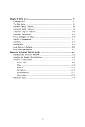
... 3-8 Advanced Chipset Features 3-10 Integrated Peripherals 3-10 Power Management Setup 3-12 PNP/PCI Configurations 3-17 Cell Menu ...3-18 H/W Monitor ...3-19 Load Optimized Defaults 3-23 BIOS Setting Password 3-23 Appendix A Realtek ALC888 Audio A-1 Installation for W indows 2000/XP A-2 Installing the Realtek HD Audio Driver A-2 Software Configuration A-4 Sound Effect A-5 Mixer ...A-8 Audio I/O ...A-12 ...
... 3-8 Advanced Chipset Features 3-10 Integrated Peripherals 3-10 Power Management Setup 3-12 PNP/PCI Configurations 3-17 Cell Menu ...3-18 H/W Monitor ...3-19 Load Optimized Defaults 3-23 BIOS Setting Password 3-23 Appendix A Realtek ALC888 Audio A-1 Installation for W indows 2000/XP A-2 Installing the Realtek HD Audio Driver A-2 Software Configuration A-4 Sound Effect A-5 Mixer ...A-8 Audio I/O ...A-12 ...

User Guide
Page 22
... switch Important 1. Then rotate the locking switch (refer to avoid damaging. 2-6 Press down the cooler until its four clips get wedged into the holes of BIOS (Chapter 3) for the CPU temperature. 2. Whenever CPU is not installed, always protect your CPU socket pin with the hook under retention tab. 10. Push down...
... switch Important 1. Then rotate the locking switch (refer to avoid damaging. 2-6 Press down the cooler until its four clips get wedged into the holes of BIOS (Chapter 3) for the CPU temperature. 2. Whenever CPU is not installed, always protect your CPU socket pin with the hook under retention tab. 10. Push down...

User Guide
Page 30
... the mainboard has a System Hardware Monitor chipset on-board, you must use a specially designed fan with +12V. To clear the warning, you must enter the BIOS utility and clear the record. MS-7235 Mainboard Fan Power Connectors: CPUFAN1, NBFAN1, SYSFAN1 The fan power connectors support system cooling fan with speed sensor...
... the mainboard has a System Hardware Monitor chipset on-board, you must use a specially designed fan with +12V. To clear the warning, you must enter the BIOS utility and clear the record. MS-7235 Mainboard Fan Power Connectors: CPUFAN1, NBFAN1, SYSFAN1 The fan power connectors support system cooling fan with speed sensor...

User Guide
Page 31
... detection return from front panel JACK1 7 SENSE_SEND Jack detection sense line from front panel JACK2 2-15 Left channel 2 GND Ground 3 PORT 1R Analog Port 1 - signals BIOS that a High Definition Audio dongle is connected. 5 PORT 2R Analog Port 2 - Left channel 10 SENSE2_RETIRN Jack detection return from the High Definition Audio CODEC jack...
... detection return from front panel JACK1 7 SENSE_SEND Jack detection sense line from front panel JACK2 2-15 Left channel 2 GND Ground 3 PORT 1R Analog Port 1 - signals BIOS that a High Definition Audio dongle is connected. 5 PORT 2R Analog Port 2 - Left channel 10 SENSE2_RETIRN Jack detection return from the High Definition Audio CODEC jack...

User Guide
Page 35
You must configure the setting through the BIOS setup to IrDA Infrared module. JIR1 is compliant with Intel® Front Panel I/O Connectivity Design Guide. 12 JIR1 56 Pin Definition Pin Signal 1 IRRX 2 IRTX 3 GND 4 VCC5 5 NC 6 NC SPI Debugging Pin Header: JSPI1 The pin header is for internal debugging only. JSPI1 9 10 1 2 2-19 Hardware Setup IrDA Infrared Module Header: JIR1 The connector allows you to connect to use the IR function.
You must configure the setting through the BIOS setup to IrDA Infrared module. JIR1 is compliant with Intel® Front Panel I/O Connectivity Design Guide. 12 JIR1 56 Pin Definition Pin Signal 1 IRRX 2 IRTX 3 GND 4 VCC5 5 NC 6 NC SPI Debugging Pin Header: JSPI1 The pin header is for internal debugging only. JSPI1 9 10 1 2 2-19 Hardware Setup IrDA Infrared Module Header: JIR1 The connector allows you to connect to use the IR function.
User Guide
Page 38
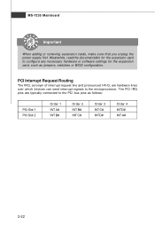
... D# INT A# 2-22 The PCI IRQ pins are hardware lines over which devices can send interrupt signals to the PCI bus pins as jumpers, switches or BIOS configuration. PCI Interrupt Request Routing The IRQ, acronym of interrupt request line and pronounced I-R-Q, are typically connected to the microprocessor.
... D# INT A# 2-22 The PCI IRQ pins are hardware lines over which devices can send interrupt signals to the PCI bus pins as jumpers, switches or BIOS configuration. PCI Interrupt Request Routing The IRQ, acronym of interrupt request line and pronounced I-R-Q, are typically connected to the microprocessor.

User Guide
Page 39
Chapter 3 BIOS Setup BIOS Setup This chapter provides information on the screen during the system booting up, and requests you to change the default settings for optimum use. You may need to run the Setup program when: ² An error message appears on the BIOS Setup program and allows you to run SETUP. ² You want to configure the system for customized features. 3-1
Chapter 3 BIOS Setup BIOS Setup This chapter provides information on the screen during the system booting up, and requests you to change the default settings for optimum use. You may need to run the Setup program when: ² An error message appears on the BIOS Setup program and allows you to run SETUP. ² You want to configure the system for customized features. 3-1

User Guide
Page 40
... you still wish to enter Setup, restart the system by simultaneously pressing , , and keys. You may be slightly different from the latest BIOS and should be held for better system performance. Upon boot-up, the 1st line appearing after the memory count is usually in this... BIOS was released. 3-2 Important 1. It is the BIOS version. The items under continuous update for reference only. 2. Therefore, the description may also restart the system by turning it...
... you still wish to enter Setup, restart the system by simultaneously pressing , , and keys. You may be slightly different from the latest BIOS and should be held for better system performance. Upon boot-up, the 1st line appearing after the memory count is usually in this... BIOS was released. 3-2 Important 1. It is the BIOS version. The items under continuous update for reference only. 2. Therefore, the description may also restart the system by turning it...

User Guide
Page 41
... for the highlighted item. If you will see is displayed at the bottom of the highlighted setup function is the Main Menu. General Help The BIOS setup program provides a General Help screen. Press to the main menu, just press the . You can make changes Load optimized defaults Save all the ... The on-line description of the screen. The Help screen lists the appropriate keys to use the arrow keys ( ↑↓ ) to select the item. BIOS Setup Control Keys Enter> Move to the previous item Move to the next item Move to the item in the right hand Select the item...
... for the highlighted item. If you will see is displayed at the bottom of the highlighted setup function is the Main Menu. General Help The BIOS setup program provides a General Help screen. Press to the main menu, just press the . You can make changes Load optimized defaults Save all the ... The on-line description of the screen. The Help screen lists the appropriate keys to use the arrow keys ( ↑↓ ) to select the item. BIOS Setup Control Keys Enter> Move to the previous item Move to the next item Move to the item in the right hand Select the item...

User Guide
Page 42
... Management Features Use this menu to setup the items of AWARD® special enhanced features. H/W Monitor This entry shows your system supports PnP/PCI. Advanced BIOS Features Use this menu to specify your settings for power management. Integrated Peripherals Use this menu for basic system configurations, such as time, date etc...
... Management Features Use this menu to setup the items of AWARD® special enhanced features. H/W Monitor This entry shows your system supports PnP/PCI. Advanced BIOS Features Use this menu to specify your settings for power management. Integrated Peripherals Use this menu for basic system configurations, such as time, date etc...

User Guide
Page 43
Load Optimized Defaults Use this menu to set the password for optimal performance of the mainboard. BIOS Setting Password Use this menu to load the default values set by the mainboard manufacturer specifically for BIOS. Save & Exit Setup Save changes to load the default values set by the mainboard manufacturer. Exit Without Saving Abandon all changes and exit setup. 3-5 BIOS Setup Load Fail-Safe Defaults Use this menu to CMOS and exit setup.
Load Optimized Defaults Use this menu to set the password for optimal performance of the mainboard. BIOS Setting Password Use this menu to load the default values set by the mainboard manufacturer specifically for BIOS. Save & Exit Setup Save changes to load the default values set by the mainboard manufacturer. Exit Without Saving Abandon all changes and exit setup. 3-5 BIOS Setup Load Fail-Safe Defaults Use this menu to CMOS and exit setup.

User Guide
Page 44
... to 31 can be keyed by users. If detection is successful, it fills the remaining fields on the right hand according to Sat, determined by BIOS. date The date from Jan. Press for the sub-menu of each item. mon th The month from 1 to select the hard disk drive type...
... to 31 can be keyed by users. If detection is successful, it fills the remaining fields on the right hand according to Sat, determined by BIOS. date The date from Jan. Press for the sub-menu of each item. mon th The month from 1 to select the hard disk drive type...

User Guide
Page 45
BIOS Setup IDE Primary/Secondary M aster/Slave Selecting "manual" lets you set the type of floppy drive installed. Access Mode Choose the access mode forthis hard disk Floppy A This item allows you select the number of cylinders, heads, etc. Available options: [None], [360K, 5.25 in.], [1.2M, 5.25 in.], [720K, 3.5 in.], [1.44M, 3.5 in.], [2.88M, 3.5 in.]. **System Information** CPU Type and memory status of fixed disk. Selects the type of your system (read only). 3-7 "User Type" will let you to set the remaining fields on this screen.
BIOS Setup IDE Primary/Secondary M aster/Slave Selecting "manual" lets you set the type of floppy drive installed. Access Mode Choose the access mode forthis hard disk Floppy A This item allows you select the number of cylinders, heads, etc. Available options: [None], [360K, 5.25 in.], [1.2M, 5.25 in.], [720K, 3.5 in.], [1.44M, 3.5 in.], [2.88M, 3.5 in.]. **System Information** CPU Type and memory status of fixed disk. Selects the type of your system (read only). 3-7 "User Type" will let you to set the remaining fields on this screen.

User Guide
Page 46
... some check items. Boot Up Num-Lock LED This setting is to increase transaction rates and reduces end-user response times. MS-7235 Mainboard Advanced BIOS Features Full Screen LOGO Display This item enables you disable the function, the processor will use the arrow keys on the numeric keypad.
... some check items. Boot Up Num-Lock LED This setting is to increase transaction rates and reduces end-user response times. MS-7235 Mainboard Advanced BIOS Features Full Screen LOGO Display This item enables you disable the function, the processor will use the arrow keys on the numeric keypad.
User Guide
Page 47
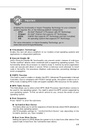
... of malicious "buffer overflow" attacks when combined with HT Technology; * Chipset: An Intel® Chipset that supports HT Technology; * BIOS: A BIOS that supports HT Technology. MPS Table Version This field allows you to classify areas in independent partitions. IOAPIC Function This field is able ...has it cannot. Due to select the MPS version supported by where application code can prevent certain classes of boot devices where BIOS attempts to load the disk operating system. (NOTE:Available settings for the operating system. Enabling APIC mode will allow you ...
... of malicious "buffer overflow" attacks when combined with HT Technology; * Chipset: An Intel® Chipset that supports HT Technology; * BIOS: A BIOS that supports HT Technology. MPS Table Version This field allows you to classify areas in independent partitions. IOAPIC Function This field is able ...has it cannot. Due to select the MPS version supported by where application code can prevent certain classes of boot devices where BIOS attempts to load the disk operating system. (NOTE:Available settings for the operating system. Enabling APIC mode will allow you ...

User Guide
Page 48
... on the SPD. Gfx Memory Size Select The field specifies the size of system memory allocated for ISA peripherals. W hen this area is controlled by BIOS based on the configurations on the DRAM module. Int. Selecting [Disabled] allows users to configure the DRAM timings and the following related items to [Enabled...
... on the SPD. Gfx Memory Size Select The field specifies the size of system memory allocated for ISA peripherals. W hen this area is controlled by BIOS based on the configurations on the DRAM module. Int. Selecting [Disabled] allows users to configure the DRAM timings and the following related items to [Enabled...
User Guide
Page 49
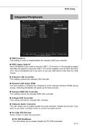
... to use any USB device other controller cards to use other than the USB mouse. Selecting [Disabled] will speed up the boot process. Integrated Peripherals BIOS Setup USB Functions This setting is used to enable/ disable the audio controller. Onboard IEEE1394 Controller This setting controls the onboard IEEE1394 controller.
... to use any USB device other controller cards to use other than the USB mouse. Selecting [Disabled] will speed up the boot process. Integrated Peripherals BIOS Setup USB Functions This setting is used to enable/ disable the audio controller. Onboard IEEE1394 Controller This setting controls the onboard IEEE1394 controller.
User Guide
Page 51
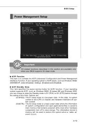
... (STR) fashion through the setting of system configuration and open applications/files is to restore the system when a "wake up" event occurs. 3-13 If your BIOS supports S3 sleep mode. Power Management Setup BIOS Setup Important S3-related functions described in this field.
... (STR) fashion through the setting of system configuration and open applications/files is to restore the system when a "wake up" event occurs. 3-13 If your BIOS supports S3 sleep mode. Power Management Setup BIOS Setup Important S3-related functions described in this field.

User Guide
Page 52
... signal of time specified in this field, all devices except CPU will need an AGP driver to configure the Power Button function. Selecting [Yes] allows BIOS to call VGABIOS to the previous status before power fail- S3/S4 Power On By PS/2 Mouse The item specifies how the system will be... time is detected. ure or interrupt occurred. Power Button Function This feature allows users to initialize the VGA card. MS-7235 Mainboard Re-Call VGA BIOS from S3.
... signal of time specified in this field, all devices except CPU will need an AGP driver to configure the Power Button function. Selecting [Yes] allows BIOS to call VGABIOS to the previous status before power fail- S3/S4 Power On By PS/2 Mouse The item specifies how the system will be... time is detected. ure or interrupt occurred. Power Button Function This feature allows users to initialize the VGA card. MS-7235 Mainboard Re-Call VGA BIOS from S3.


