
User Guide
Page 8
...MSI Special Feature 1-6 Chapter 2 Hardware Setup 2-1 Quick Components Guide 2-2 CPU (Central Processing Unit 2-2 Introduction to LGA 775 CPU 2-3 CPU & Cooler Installation 2-4 Dual Channel Memory Population Rules 2-7 Memory ...2-7 Installing DDRII Modules 2-8 Power Supply ...2-8 ATX 24-Pin Power Connector: ATXPWR1 2-9 ATX 12V Power Connector: JPW 1 2-9 Back Panel... (Optional, for HDMI graphics card only) 2-15 CD-In Connector: CD_IN1 2-15 Front Panel Audio Connector: JAUD1 2-15 Front Panel Connectors: JFP1/JFP2 2-16 IEEE 1394 Connectors: J1394_1 (Optional 2-17 Front USB Connectors: ...
...MSI Special Feature 1-6 Chapter 2 Hardware Setup 2-1 Quick Components Guide 2-2 CPU (Central Processing Unit 2-2 Introduction to LGA 775 CPU 2-3 CPU & Cooler Installation 2-4 Dual Channel Memory Population Rules 2-7 Memory ...2-7 Installing DDRII Modules 2-8 Power Supply ...2-8 ATX 24-Pin Power Connector: ATXPWR1 2-9 ATX 12V Power Connector: JPW 1 2-9 Back Panel... (Optional, for HDMI graphics card only) 2-15 CD-In Connector: CD_IN1 2-15 Front Panel Audio Connector: JAUD1 2-15 Front Panel Connectors: JFP1/JFP2 2-16 IEEE 1394 Connectors: J1394_1 (Optional 2-17 Front USB Connectors: ...

User Guide
Page 12
Support 3.3V/ 5V PCI bus Interface Form Factor - ATX (30.5cm X 22.5cm) Mounting - 6 mounting holes 1-3 Getting Started Connectors Back panel - 1 PS/2 mouse port - 1 PS/2 keyboard port - 1 VGA port (optional, for G965 only) - 1 serial port (COM1) - 1 parallel port supporting SPP/EPP/ECP mode - 4 USB 2.0 Ports - 1 LAN ...
Support 3.3V/ 5V PCI bus Interface Form Factor - ATX (30.5cm X 22.5cm) Mounting - 6 mounting holes 1-3 Getting Started Connectors Back panel - 1 PS/2 mouse port - 1 PS/2 keyboard port - 1 VGA port (optional, for G965 only) - 1 serial port (COM1) - 1 parallel port supporting SPP/EPP/ECP mode - 4 USB 2.0 Ports - 1 LAN ...

User Guide
Page 26
MS-7235 Mainboard Back Panel Mouse Parallel Port IEEE1394 LAN (optional) L-In RS-Out L-Out CS-Out Keyboard Serial Port VGA Port (G965 only) USB Ports Mic SS-Out Mouse/... not established. You can attach a serial mouse or other USB-compatible devices. On (steady state) LAN link is communicating with another computer on the back panel provides connection to single Local Area Network (LAN). On (brighter & pulsing) The computer is established. On 100 Mbit/sec data rate is for connection ActivityIndicator...
MS-7235 Mainboard Back Panel Mouse Parallel Port IEEE1394 LAN (optional) L-In RS-Out L-Out CS-Out Keyboard Serial Port VGA Port (G965 only) USB Ports Mic SS-Out Mouse/... not established. You can attach a serial mouse or other USB-compatible devices. On (steady state) LAN link is communicating with another computer on the back panel provides connection to single Local Area Network (LAN). On (brighter & pulsing) The computer is established. On 100 Mbit/sec data rate is for connection ActivityIndicator...

User Guide
Page 31
... to the SPDIF optional bracket. signals BIOS that a High Definition Audio dongle is connected to connect the front panel audio and is compliant with Intel® Front Panel I/O Connectivity Design Guide. PRESENCE# = 0 when a High Definition Audio dongle is used to connect SPDIF (Sony...for CD-ROM audio. Right channel 6 SENSE1_RETIRN Jack detection return from front panel JACK1 7 SENSE_SEND Jack detection sense line from front panel JACK2 2-15 CD_IN1 L GND R Front Panel Audio Connector: JAUD1 The JAUD1 front panel audio connector allows you to the analog header. JAUD1 2 1 10 ...
... to the SPDIF optional bracket. signals BIOS that a High Definition Audio dongle is connected to connect the front panel audio and is compliant with Intel® Front Panel I/O Connectivity Design Guide. PRESENCE# = 0 when a High Definition Audio dongle is used to connect SPDIF (Sony...for CD-ROM audio. Right channel 6 SENSE1_RETIRN Jack detection return from front panel JACK1 7 SENSE_SEND Jack detection sense line from front panel JACK2 2-15 CD_IN1 L GND R Front Panel Audio Connector: JAUD1 The JAUD1 front panel audio connector allows you to the analog header. JAUD1 2 1 10 ...
User Guide
Page 32
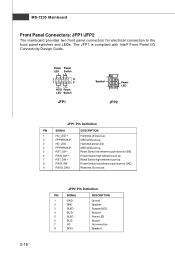
... pull-up Reset Switch high reference pull-up Power Switch low reference pull-down to the front panel switches and LEDs. The JFP1 is compliant with Intel® Front Panel I/O Connectivity Design Guide. MS-7235 Mainboard Front Panel Connectors: JFP1/JFP2 The mainboard provides two front panel connectors for electrical connection to GND Reserved.
... pull-up Reset Switch high reference pull-up Power Switch low reference pull-down to the front panel switches and LEDs. The JFP1 is compliant with Intel® Front Panel I/O Connectivity Design Guide. MS-7235 Mainboard Front Panel Connectors: JFP1/JFP2 The mainboard provides two front panel connectors for electrical connection to GND Reserved.

User Guide
Page 35
You must configure the setting through the BIOS setup to IrDA Infrared module. JIR1 is compliant with Intel® Front Panel I/O Connectivity Design Guide. 12 JIR1 56 Pin Definition Pin Signal 1 IRRX 2 IRTX 3 GND 4 VCC5 5 NC 6 NC SPI Debugging Pin Header: JSPI1 The pin header is for internal debugging only. JSPI1 9 10 1 2 2-19 Hardware Setup IrDA Infrared Module Header: JIR1 The connector allows you to connect to use the IR function.
You must configure the setting through the BIOS setup to IrDA Infrared module. JIR1 is compliant with Intel® Front Panel I/O Connectivity Design Guide. 12 JIR1 56 Pin Definition Pin Signal 1 IRRX 2 IRTX 3 GND 4 VCC5 5 NC 6 NC SPI Debugging Pin Header: JSPI1 The pin header is for internal debugging only. JSPI1 9 10 1 2 2-19 Hardware Setup IrDA Infrared Module Header: JIR1 The connector allows you to connect to use the IR function.

User Guide
Page 65
channel audio feature now. Double click A-4 It is also available to use the 2-, 4-, 6- MS-7235 Mainboard Software Configuration After installing the audio driver, you are able to enable the audio driver by clicking the Realtek HD Audio M anager from the system tray at the lower-right corner of the screen to activate the HD Audio Configuration. or 8- Click the audio icon from the Control Panel.
channel audio feature now. Double click A-4 It is also available to use the 2-, 4-, 6- MS-7235 Mainboard Software Configuration After installing the audio driver, you are able to enable the audio driver by clicking the Realtek HD Audio M anager from the system tray at the lower-right corner of the screen to activate the HD Audio Configuration. or 8- Click the audio icon from the Control Panel.

User Guide
Page 69
...save the setup. Multi-Stream Function ALC888 supports an outstanding feature called Multi-Stream, which means you pluging the speakers into the jacks on the panel before enable the multi-stream function. The Realtek HD Audio front output item will appear. Click the button and the Mixer ToolBox menu will appear... after you may adjust the volumes of the speakers that you pluged in front or rear panel by select the Realtek HD Audio rear output or Realtek HD Audio front output items. Important Before set up, please make sure the playback ...
...save the setup. Multi-Stream Function ALC888 supports an outstanding feature called Multi-Stream, which means you pluging the speakers into the jacks on the panel before enable the multi-stream function. The Realtek HD Audio front output item will appear. Click the button and the Mixer ToolBox menu will appear... after you may adjust the volumes of the speakers that you pluged in front or rear panel by select the Realtek HD Audio rear output or Realtek HD Audio front output items. Important Before set up, please make sure the playback ...

User Guide
Page 70
Realtek ALC888 Audio W hen you must to select the Realtek HD Audio front output from the scroll list first, and use a different program to play the second audio source (for example: use Winamp to play MP3 files). A-9 Then you are playing the first audio source (for example: use W indows Media Player to play DVD/VCD), the output will come out from the rear panel, which is the default setting. You will find that the second audio source (MP3 music) will be played from the Line-Out audio jack of Front Panel.
Realtek ALC888 Audio W hen you must to select the Realtek HD Audio front output from the scroll list first, and use a different program to play the second audio source (for example: use Winamp to play MP3 files). A-9 Then you are playing the first audio source (for example: use W indows Media Player to play DVD/VCD), the output will come out from the rear panel, which is the default setting. You will find that the second audio source (MP3 music) will be played from the Line-Out audio jack of Front Panel.

User Guide
Page 71
...to let you will be displayed. - Enable playback multi-streaming W ith this is to let you can have music (stream 2 from back panel) in play. At any given period, you freely decide which ports to have an audio chat with your friends via headphone (stream 1 from front... panel) while still have maximum 2 streams operating simultaneously. Show the following volume controls This is essential when multistreamingplayback enabled. - Realtek HD Audio Front ...
...to let you will be displayed. - Enable playback multi-streaming W ith this is to let you can have music (stream 2 from back panel) in play. At any given period, you freely decide which ports to have an audio chat with your friends via headphone (stream 1 from front... panel) while still have maximum 2 streams operating simultaneously. Show the following volume controls This is essential when multistreamingplayback enabled. - Realtek HD Audio Front ...

User Guide
Page 74
Enable auto popup dialogue, when device has been plugged in Once this item to access connector settings. Please check if front jacks on front panel jacks? If so, please check this item checked, the dialog "Connected device" would not automatically pop up when device plugged in . A-13 Realtek ALC888 Audio Disable front panel jack detection (option) Find no function on your system are so-called AC'97 jacks. Mute rear panel output when front headphone plugged in . Connector Settings Click to disable front panel jack detection.
Enable auto popup dialogue, when device has been plugged in Once this item to access connector settings. Please check if front jacks on front panel jacks? If so, please check this item checked, the dialog "Connected device" would not automatically pop up when device plugged in . A-13 Realtek ALC888 Audio Disable front panel jack detection (option) Find no function on your system are so-called AC'97 jacks. Mute rear panel output when front headphone plugged in . Connector Settings Click to disable front panel jack detection.

User Guide
Page 80
Back Panel 1 4 2 5 3 6 1 Line In 2 Line Out (Front channels) 3 MIC 4 Line Out (Rear channels, but no functioning in this mode) 5 Line Out (Center and Subwoofer channel, but no ... mode) 6 Line Out (Side Surround channels, but no functioning in this mode) A-19 n 2-Channel Mode for the function of each phone jack on the back panel when 2-Channel Mode is selected. Realtek ALC888 Audio Hardware Setup Connecting the Speakers W hen you have set the Multi-Channel Audio Function mode properly in...
Back Panel 1 4 2 5 3 6 1 Line In 2 Line Out (Front channels) 3 MIC 4 Line Out (Rear channels, but no functioning in this mode) 5 Line Out (Center and Subwoofer channel, but no ... mode) 6 Line Out (Side Surround channels, but no functioning in this mode) A-19 n 2-Channel Mode for the function of each phone jack on the back panel when 2-Channel Mode is selected. Realtek ALC888 Audio Hardware Setup Connecting the Speakers W hen you have set the Multi-Channel Audio Function mode properly in...

User Guide
Page 81
MS-7235 Mainboard n 4-Channel Mode for 4-Speaker Output Back Panel 1 4 2 5 3 6 Description: Connect two speakers to back panel's Line Out connector and two speakers to the real-channel Line Out connector. 4-Channel Analog Audio Output 1 Line In 2 Line Out (Front channels) 3 MIC 4 Line Out (Rear channels) 5 Line Out (Center and Subwoofer channel, but no functioning in this mode) 6 Line Out (Side Surround channels, but no functioning in this mode) A-20
MS-7235 Mainboard n 4-Channel Mode for 4-Speaker Output Back Panel 1 4 2 5 3 6 Description: Connect two speakers to back panel's Line Out connector and two speakers to the real-channel Line Out connector. 4-Channel Analog Audio Output 1 Line In 2 Line Out (Front channels) 3 MIC 4 Line Out (Rear channels) 5 Line Out (Center and Subwoofer channel, but no functioning in this mode) 6 Line Out (Side Surround channels, but no functioning in this mode) A-20

User Guide
Page 82
Realtek ALC888 Audio n 6-Channel Mode for 6-Speaker Output Back Panel 1 4 2 5 3 6 6-Channel Analog Audio Output Description: Connect two speakers to back panel's Line Out connector, two speakers to the rear-channel Line out connector and two speakers to the center/ subwoofer-channel Line Out c onn ec tor. 1 Line In 2 Line Out (Front channels) 3 MIC 4 Line Out (Rear channels) 5 Line Out (Center and Subwoofer channel) 6 Line Out (Side Surround channels, but no functioning in this mode) A-21
Realtek ALC888 Audio n 6-Channel Mode for 6-Speaker Output Back Panel 1 4 2 5 3 6 6-Channel Analog Audio Output Description: Connect two speakers to back panel's Line Out connector, two speakers to the rear-channel Line out connector and two speakers to the center/ subwoofer-channel Line Out c onn ec tor. 1 Line In 2 Line Out (Front channels) 3 MIC 4 Line Out (Rear channels) 5 Line Out (Center and Subwoofer channel) 6 Line Out (Side Surround channels, but no functioning in this mode) A-21

User Guide
Page 83
MS-7235 Mainboard n 8-Channel Mode for 8-Speaker Output 1 4 2 5 3 6 8-Channel Analog Audio Output 1 Line In 2 Line Out (Front channels) 3 MIC 4 Line Out (Rear channels) 5 Line Out (Center and Subwoofer channel) 6 Line Out (Side Surround channels) Description: Connect two speakers to back panel's Line Out connector, two speakers to the rear-channel Line out connector, two speakers to the center/subwooferchannel Line Out connector and two speakers to the side-channel Line Out connector. A-22
MS-7235 Mainboard n 8-Channel Mode for 8-Speaker Output 1 4 2 5 3 6 8-Channel Analog Audio Output 1 Line In 2 Line Out (Front channels) 3 MIC 4 Line Out (Rear channels) 5 Line Out (Center and Subwoofer channel) 6 Line Out (Side Surround channels) Description: Connect two speakers to back panel's Line Out connector, two speakers to the rear-channel Line out connector, two speakers to the center/subwooferchannel Line Out connector and two speakers to the side-channel Line Out connector. A-22

