
User Guide
Page 8
CONTENTS Chapter 1 Getting started 1-1 Mainboard Specifications 1-2 Mainboard Layout 1-4 Packing Checklist 1-4 MSI Special Feature 1-6 Chapter 2 Hardware Setup 2-1 Quick Components Guide 2-2 CPU (Central Processing Unit 2-2 Introduction to LGA 775 CPU 2-3 CPU & Cooler Installation 2-4 Dual Channel Memory Population Rules 2-7 Memory ...2-7 Installing DDRII Modules 2-8 Power Supply ...2-8 ATX 24-Pin Power Connector: ATXPWR1 2-9 ATX 12V Power Connector: JPW 1 2-9 Back Panel ...2-11...
CONTENTS Chapter 1 Getting started 1-1 Mainboard Specifications 1-2 Mainboard Layout 1-4 Packing Checklist 1-4 MSI Special Feature 1-6 Chapter 2 Hardware Setup 2-1 Quick Components Guide 2-2 CPU (Central Processing Unit 2-2 Introduction to LGA 775 CPU 2-3 CPU & Cooler Installation 2-4 Dual Channel Memory Population Rules 2-7 Memory ...2-7 Installing DDRII Modules 2-8 Power Supply ...2-8 ATX 24-Pin Power Connector: ATXPWR1 2-9 ATX 12V Power Connector: JPW 1 2-9 Back Panel ...2-11...
User Guide
Page 10
The P965Neo-F V2 Series mainboards are based on Intel® P965 / G965 & ICH8 chipsets for choosing the P965Neo-F V2 Series (MS7235 v2.X) ATX mainboard. Getting Started Chapter 1 Getting Started Thank you for optimal system efficiency. Designed to fit the advanced Intel® Pentium 4 LGA775 series processors, the P965Neo-F V2 Series deliver a high performance and professional desktop platform solution. 1-1
The P965Neo-F V2 Series mainboards are based on Intel® P965 / G965 & ICH8 chipsets for choosing the P965Neo-F V2 Series (MS7235 v2.X) ATX mainboard. Getting Started Chapter 1 Getting Started Thank you for optimal system efficiency. Designed to fit the advanced Intel® Pentium 4 LGA775 series processors, the P965Neo-F V2 Series deliver a high performance and professional desktop platform solution. 1-1

User Guide
Page 11
...real x 1 Floppy - 1 floppy port - Supports 4 pin CPU Fan Pin-Header with Azalia 1.0 Spec - North Bridge: Intel® P965/ G965 chipset - msi.com.tw/program/products/mainboard/mbd/pro_m bd_trp_list.php) LAN - Meet Microsoft Vista Premium spec IDE - 1 IDE port by Realtek 8110SC Audio - Supports PIO, Bus Master...174; ALC888 - Supports Intel Quad Core / Dual Core Technology up to 1066 MHz (For the latest information about CPU, please visit http://www.msi. DDRII 800/667/533 SDRAM (8GB Max) - 4 DDRII DIMMs (240pin / 1.8V) (For the updated supporting memory modules, please visit http...
...real x 1 Floppy - 1 floppy port - Supports 4 pin CPU Fan Pin-Header with Azalia 1.0 Spec - North Bridge: Intel® P965/ G965 chipset - msi.com.tw/program/products/mainboard/mbd/pro_m bd_trp_list.php) LAN - Meet Microsoft Vista Premium spec IDE - 1 IDE port by Realtek 8110SC Audio - Supports PIO, Bus Master...174; ALC888 - Supports Intel Quad Core / Dual Core Technology up to 1066 MHz (For the latest information about CPU, please visit http://www.msi. DDRII 800/667/533 SDRAM (8GB Max) - 4 DDRII DIMMs (240pin / 1.8V) (For the updated supporting memory modules, please visit http...

User Guide
Page 13
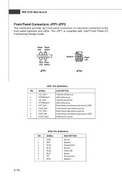
... FA N1 RTL8110SC PCIE2 Intel P965/ G965 VT 63 08 P (optional) PCIE3 Intel ICH8 ALC888 PCI 1 PCI 2 JSP I1 BATT + JAUD1 CD_IN1 J1394_1 (optional) JSPD1 (optional) FDD1 JUSB2 JUSB3 JBAT1 JUSB4 JFP1 P965Neo-F V2 Series (MS-7235 v2.X) ATX Mainboard 1-4 SATA7 IDE1 SATA4 SATA3 ...SATA2 SATA1 JFP2 Ou t B:Mic T:RS - MS-7235 Mainboard Mainboard Layout Top : mouse Bottom: keyboard JPW1 Top : Parallel Port Bottom: COM portA VGA port (G965...
... FA N1 RTL8110SC PCIE2 Intel P965/ G965 VT 63 08 P (optional) PCIE3 Intel ICH8 ALC888 PCI 1 PCI 2 JSP I1 BATT + JAUD1 CD_IN1 J1394_1 (optional) JSPD1 (optional) FDD1 JUSB2 JUSB3 JBAT1 JUSB4 JFP1 P965Neo-F V2 Series (MS-7235 v2.X) ATX Mainboard 1-4 SATA7 IDE1 SATA4 SATA3 ...SATA2 SATA1 JFP2 Ou t B:Mic T:RS - MS-7235 Mainboard Mainboard Layout Top : mouse Bottom: keyboard JPW1 Top : Parallel Port Bottom: COM portA VGA port (G965...

User Guide
Page 15
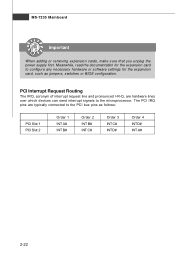
... system status during real time operation. In the right side it shows the current system status, including the Vcore, 3.3V, +5V and 12V. MS-7235 Mainboard MSI Special Feature The Core Center is just like your PC doctor that can find in the left side it shows the current PC hardware status...
... system status during real time operation. In the right side it shows the current system status, including the Vcore, 3.3V, +5V and 12V. MS-7235 Mainboard MSI Special Feature The Core Center is just like your PC doctor that can find in the left side it shows the current PC hardware status...

User Guide
Page 19
...damage the CPU and system. While replacing the CPU, always turn off the ATX power supply or unplug the power supply's power cord from overheating. 2. Important 1. Hardware Setup CPU (Central Processing Unit) This mainboard supports Intel® Pentium 4, Pentium D, CoreTM 2 processor in LGA 775 ...LGA 775 CPU. The surface of LGA 775 CPU. For the latest information about CPU, please visit http://www.msi.com.tw/program/ products/mainboard/mbd/pro_mbd_cpu_support.php. Introduction to enhance heat dissipation. 3. Always make sure to install the cooler to purchase and install...
...damage the CPU and system. While replacing the CPU, always turn off the ATX power supply or unplug the power supply's power cord from overheating. 2. Important 1. Hardware Setup CPU (Central Processing Unit) This mainboard supports Intel® Pentium 4, Pentium D, CoreTM 2 processor in LGA 775 ...LGA 775 CPU. The surface of LGA 775 CPU. For the latest information about CPU, please visit http://www.msi.com.tw/program/ products/mainboard/mbd/pro_mbd_cpu_support.php. Introduction to enhance heat dissipation. 3. Always make sure to install the cooler to purchase and install...

User Guide
Page 20
MS-7235 Mainboard CPU & Cooler Installation W hen you do not forget to protect the socket pin. 2. W rong installation will cause the damage of socket reveal. 4. Open the load ... CPU before turning on it to install the CPU & cooler correctly. Remove the cap from damage. Meanwhile, do not have the cooler, contact your CPU & mainboard. 1. Follow the steps below to protect the contact from lever hinge side (as the arrow shows). 3. The CPU has a plastic cap on the computer.
MS-7235 Mainboard CPU & Cooler Installation W hen you do not forget to protect the socket pin. 2. W rong installation will cause the damage of socket reveal. 4. Open the load ... CPU before turning on it to install the CPU & cooler correctly. Remove the cap from damage. Meanwhile, do not have the cooler, contact your CPU & mainboard. 1. Follow the steps below to protect the contact from lever hinge side (as the arrow shows). 3. The CPU has a plastic cap on the computer.

User Guide
Page 22
... the load lever lightly onto the load plate, and then secure the lever with the plastic cap covered (shown in H/W M onitor of the mainboard. 11. Turn over the mainboard to lock the h ook s . 12. locking switch Important 1. Align the holes on it) to confirm that the clip-ends are correctly inserted. Press... information in Figure 1) to fasten the cooler. Push down to avoid damaging. 2-6 Then rotate the locking switch (refer to the correct direction marked on the mainboard with the heatsink. MS-7235...
... the load lever lightly onto the load plate, and then secure the lever with the plastic cap covered (shown in H/W M onitor of the mainboard. 11. Turn over the mainboard to lock the h ook s . 12. locking switch Important 1. Align the holes on it) to confirm that the clip-ends are correctly inserted. Press... information in Figure 1) to fasten the cooler. Push down to avoid damaging. 2-6 Then rotate the locking switch (refer to the correct direction marked on the mainboard with the heatsink. MS-7235...

User Guide
Page 23
Channel B in GREEN; For more information on compatible components, please visit http://www.msi.com.tw/ p ro gr a m/ pr od u c t s / m ainb o ar d/ mb d /p ro _ mb d_ t rp _lis t .p hp . DIMM1 DIMM2 DIMM3 DIMM4 DIMM1 DIMM2 DIMM3 DIMM4 DIMM1 DIMM2 DIMM3 DIMM4 2-7 DDRII 240-pin, 1.8V 64x2=128 pin 56x2=112 pin Single-Channel: All DIMMs in GREEN Dual-Channel: Channel A in ORANGE Dual Channel Memory Population Rules 1 2 3 - Hardware Setup Memory The mainboard provides four 240-pin non-ECC DDRII 800/667/533 DIMM slots and supports up to 8GB system memory.
Channel B in GREEN; For more information on compatible components, please visit http://www.msi.com.tw/ p ro gr a m/ pr od u c t s / m ainb o ar d/ mb d /p ro _ mb d_ t rp _lis t .p hp . DIMM1 DIMM2 DIMM3 DIMM4 DIMM1 DIMM2 DIMM3 DIMM4 DIMM1 DIMM2 DIMM3 DIMM4 2-7 DDRII 240-pin, 1.8V 64x2=128 pin 56x2=112 pin Single-Channel: All DIMMs in GREEN Dual-Channel: Channel A in ORANGE Dual Channel Memory Population Rules 1 2 3 - Hardware Setup Memory The mainboard provides four 240-pin non-ECC DDRII 800/667/533 DIMM slots and supports up to 8GB system memory.

User Guide
Page 24
... slots. - In dual-channel mode, make sure that you install memory modules of the DIMM slot will only fit in the right orientation. 2. MS-7235 Mainboard Installing DDRII Modules 1. You should always install DDRII memory modules in the DDRII DIMM slots and DDR memory modules in different channel DDR DIMM slots. -
... slots. - In dual-channel mode, make sure that you install memory modules of the DIMM slot will only fit in the right orientation. 2. MS-7235 Mainboard Installing DDRII Modules 1. You should always install DDRII memory modules in the DDRII DIMM slots and DDR memory modules in different channel DDR DIMM slots. -

User Guide
Page 25
... GND 8 PW R OK 20 Res 9 5VSB 21 +5V 10 +12V 22 +5V 13 11 +12V 12 NC 23 +5V 24 GND pin 13 pin 12 ATX 12V Power Connector: JPW1 This 12V power connector is highly recommended for system stability. 3. Power supply of 350 watts (and above) is used to provide... the power supply is also a foolproof design on pin 11, 12, 23 & 24 to connect an ATX 24-pin power supply. To connect the ATX 24-pin power supply, make sure the plug of the mainboard. 2. Hardware Setup Power Supply ATX 24-Pin Power Connector: ATXPWR1 This connector allows you to avoid wrong installation...
... GND 8 PW R OK 20 Res 9 5VSB 21 +5V 10 +12V 22 +5V 13 11 +12V 12 NC 23 +5V 24 GND pin 13 pin 12 ATX 12V Power Connector: JPW1 This 12V power connector is highly recommended for system stability. 3. Power supply of 350 watts (and above) is used to provide... the power supply is also a foolproof design on pin 11, 12, 23 & 24 to connect an ATX 24-pin power supply. To connect the ATX 24-pin power supply, make sure the plug of the mainboard. 2. Hardware Setup Power Supply ATX 24-Pin Power Connector: ATXPWR1 This connector allows you to avoid wrong installation...

User Guide
Page 26
... Left Orange Green Right Orange LED State Condition Off LAN link is selected. 2-10 On 1000 Mbit/sec data rate is not established. MS-7235 Mainboard Back Panel Mouse Parallel Port IEEE1394 LAN (optional) L-In RS-Out L-Out CS-Out Keyboard Serial Port VGA Port (G965 only) USB Ports Mic SS...
... Left Orange Green Right Orange LED State Condition Off LAN link is selected. 2-10 On 1000 Mbit/sec data rate is not established. MS-7235 Mainboard Back Panel Mouse Parallel Port IEEE1394 LAN (optional) L-In RS-Out L-Out CS-Out Keyboard Serial Port VGA Port (G965 only) USB Ports Mic SS...

User Guide
Page 28
... Important If you install two hard disks on cable, you must configure the second hard drive to Slave mode by setting its jumper. MS-7235 Mainboard Connectors Floppy Disk Drive Connector: FDD1 This standard FDD connector supports 360K, 720K, 1.2M, 1.44M and 2.88M floppy disk types. You can ...a Master and a Slave drive. Refer to the hard disk documentation supplied by setting the jumper accordingly. FDD1 Hard Disk Connector: IDE1 The mainboard provides a one-channel Ultra ATA 133 bus Master IDE controller that supports PIO mode 0~4, Bus Master, and Ultra DMA 66/100/133 function.
... Important If you install two hard disks on cable, you must configure the second hard drive to Slave mode by setting its jumper. MS-7235 Mainboard Connectors Floppy Disk Drive Connector: FDD1 This standard FDD connector supports 360K, 720K, 1.2M, 1.44M and 2.88M floppy disk types. You can ...a Master and a Slave drive. Refer to the hard disk documentation supplied by setting the jumper accordingly. FDD1 Hard Disk Connector: IDE1 The mainboard provides a one-channel Ultra ATA 133 bus Master IDE controller that supports PIO mode 0~4, Bus Master, and Ultra DMA 66/100/133 function.

User Guide
Page 30
...Intrusion Switch Connector: JCASE1 This connector connects to the actual CPU temperature. CINTRU 1 GND JCASE1 2-14 CPUFAN1 supports fan control. MS-7235 Mainboard Fan Power Connectors: CPUFAN1, NBFAN1, SYSFAN1 The fan power connectors support system cooling fan with speed sensor to take note that will automatically ... to the connectors, always take advantage of the CPU fan c on -board, you must use a specially designed fan with +12V. If the mainboard has a System Hardware Monitor chipset on tr ol . CONTROL GND SENSOR +1 2V CPUFAN1 SE NS OR +1 2V GND NBFAN1 GND SE NS OR...
...Intrusion Switch Connector: JCASE1 This connector connects to the actual CPU temperature. CINTRU 1 GND JCASE1 2-14 CPUFAN1 supports fan control. MS-7235 Mainboard Fan Power Connectors: CPUFAN1, NBFAN1, SYSFAN1 The fan power connectors support system cooling fan with speed sensor to take note that will automatically ... to the connectors, always take advantage of the CPU fan c on -board, you must use a specially designed fan with +12V. If the mainboard has a System Hardware Monitor chipset on tr ol . CONTROL GND SENSOR +1 2V CPUFAN1 SE NS OR +1 2V GND NBFAN1 GND SE NS OR...
User Guide
Page 32
... Panel Connectors: JFP1/JFP2 The mainboard provides two front panel connectors for electrical connection to GND Reserved. Do not use. 2-16 JFP2 Pin Definition PIN SIGNAL 1 GND 2 SPK- 3 SLED 4 BUZ+ 5 PLED 6 ...
... Panel Connectors: JFP1/JFP2 The mainboard provides two front panel connectors for electrical connection to GND Reserved. Do not use. 2-16 JFP2 Pin Definition PIN SIGNAL 1 GND 2 SPK- 3 SLED 4 BUZ+ 5 PLED 6 ...

User Guide
Page 33
Hardware Setup IEEE 1394 Connectors: J1394_1(Optional) The mainboard provides IEEE1394 pinheaders that allow you to connect IEEE 1394 ports via an external IEEE1394 bracket (optional). 9 1 10 2 J1394_1 Pin Definition PIN SIGNAL PIN 1 TPA+ 2 3 Ground 4 5 TPB+ 6 7 Cable power 8 9 Key (no pin) 10 SIGNAL TPAGround TPBCable power Ground Connected to J1394_1 Foolproof design IEEE1394 Bracket (Optional) 2-17
Hardware Setup IEEE 1394 Connectors: J1394_1(Optional) The mainboard provides IEEE1394 pinheaders that allow you to connect IEEE 1394 ports via an external IEEE1394 bracket (optional). 9 1 10 2 J1394_1 Pin Definition PIN SIGNAL PIN 1 TPA+ 2 3 Ground 4 5 TPB+ 6 7 Cable power 8 9 Key (no pin) 10 SIGNAL TPAGround TPBCable power Ground Connected to J1394_1 Foolproof design IEEE1394 Bracket (Optional) 2-17

User Guide
Page 34
... USB Connectors: JUSB2, JUSB3, JUSB4 The mainboard provides three USB 2.0 pinheaders (optional USB 2.0 bracket available) that the pins of 480Mbps, which is 40 times faster than USB 1.1, and is ideal for connecting ...
... USB Connectors: JUSB2, JUSB3, JUSB4 The mainboard provides three USB 2.0 pinheaders (optional USB 2.0 bracket available) that the pins of 480Mbps, which is 40 times faster than USB 1.1, and is ideal for connecting ...

User Guide
Page 36
... system configuration. it is turned on ; With the CMOS RAM, the system can clear CMOS by shorting 2-3 pin while the system is on . MS-7235 Mainboard Jumpers Clear CMOS Jumper: JBAT1 There is a CMOS RAM onboard that has a power supply from external battery to 1-2 pin position. Avoid clearing the CMOS while...
... system configuration. it is turned on ; With the CMOS RAM, the system can clear CMOS by shorting 2-3 pin while the system is on . MS-7235 Mainboard Jumpers Clear CMOS Jumper: JBAT1 There is a CMOS RAM onboard that has a power supply from external battery to 1-2 pin position. Avoid clearing the CMOS while...
User Guide
Page 38
The PCI IRQ pins are hardware lines over which devices can send interrupt signals to the microprocessor. MS-7235 Mainboard Important When adding or removing expansion cards, make sure that you unplug the power supply first. Meanwhile, read the documentation for the expansion card to ...
The PCI IRQ pins are hardware lines over which devices can send interrupt signals to the microprocessor. MS-7235 Mainboard Important When adding or removing expansion cards, make sure that you unplug the power supply first. Meanwhile, read the documentation for the expansion card to ...

User Guide
Page 40
... is the BIOS version. W hen the message below appears on the computer and the system will start POST (Power On Self Test) process. MS-7235 Mainboard Entering Setup Power on the screen, press key to enter Setup. The items under continuous update for reference only. 2. Important 1. Upon boot-up, the 1st...
... is the BIOS version. W hen the message below appears on the computer and the system will start POST (Power On Self Test) process. MS-7235 Mainboard Entering Setup Power on the screen, press key to enter Setup. The items under continuous update for reference only. 2. Important 1. Upon boot-up, the 1st...


