
User Guide
Page 2
...of Novell, Inc. Alternatively, please try the following help resources for FAQ, technical guide, BIOS updates, driver updates, and other countries. W indows® 95/98/2000/NT/XP...States and/or other information: http://www.msi.com.tw/program/service/faq/ faq/esc_faq_list.php Contact our technical staff at: http://support.msi.com.tw/ ii AMD, Athlon™, ... trademark of Phoenix Technologies Ltd. Revision History Revision V1.0 Revision History First release for P31 Neo Series Date July 2007 Technical Support If a problem arises with your place of NVIDIA Corporation...
...of Novell, Inc. Alternatively, please try the following help resources for FAQ, technical guide, BIOS updates, driver updates, and other countries. W indows® 95/98/2000/NT/XP...States and/or other information: http://www.msi.com.tw/program/service/faq/ faq/esc_faq_list.php Contact our technical staff at: http://support.msi.com.tw/ ii AMD, Athlon™, ... trademark of Phoenix Technologies Ltd. Revision History Revision V1.0 Revision History First release for P31 Neo Series Date July 2007 Technical Support If a problem arises with your place of NVIDIA Corporation...

User Guide
Page 8
... 2-1 Quick Components Guide 2-2 CPU (Central Processing Unit 2-3 Memory ...2-7 Power Supply ...2-9 Back Panel ...2-10 Connectors ...2-11 Jumper ...2-18 Slots ...2-19 Chapter 3 BIOS Setup 3-1 Entering Setup ...3-2 The Main Menu ...3-4 Standard CMOS Features 3-6 Advanced BIOS Features 3-9 Integrated Peripherals 3-12 Power Management Setup 3-14 PNP/PCI Configurations 3-16 H/W Monitor ...3-18 Frequency/Voltage Control 3-19 Load Fail...
... 2-1 Quick Components Guide 2-2 CPU (Central Processing Unit 2-3 Memory ...2-7 Power Supply ...2-9 Back Panel ...2-10 Connectors ...2-11 Jumper ...2-18 Slots ...2-19 Chapter 3 BIOS Setup 3-1 Entering Setup ...3-2 The Main Menu ...3-4 Standard CMOS Features 3-6 Advanced BIOS Features 3-9 Integrated Peripherals 3-12 Power Management Setup 3-14 PNP/PCI Configurations 3-16 H/W Monitor ...3-18 Frequency/Voltage Control 3-19 Load Fail...

User Guide
Page 20
... then secure the lever with the hook under retention tab. 10. Then rotate the locking switch (refer to avoid damaging. 3. Read the CPU status in BIOS (Chapter 3). 2. Align the holes on it) to confirm that the clip-ends are for demonstration of the mainboard. 11. The appearance of your CPU socket...
... then secure the lever with the hook under retention tab. 10. Then rotate the locking switch (refer to avoid damaging. 3. Read the CPU status in BIOS (Chapter 3). 2. Align the holes on it) to confirm that the clip-ends are for demonstration of the mainboard. 11. The appearance of your CPU socket...

User Guide
Page 26
... will be short. CINTRU 1 GND 2 JCI1 2-12 If the chassis is a high-speed Serial ATA interface port. To clear the warning, you must enter the BIOS utility and clear the record. SATA2 SATA4 SATA1 SATA3 Important Please do not fold the Serial ATA cable into 90-degree angle. Otherwise, data loss...
... will be short. CINTRU 1 GND 2 JCI1 2-12 If the chassis is a high-speed Serial ATA interface port. To clear the warning, you must enter the BIOS utility and clear the record. SATA2 SATA4 SATA1 SATA3 Important Please do not fold the Serial ATA cable into 90-degree angle. Otherwise, data loss...

User Guide
Page 27
Hardware Setup Fan Power Connectors: CPUFAN1, SYSFAN1, SYSFAN2 The fan power connectors support system cooling fan with speed sensor to take advantage of BIOS Setup. the black wire is Ground and should be connected to the recommended CPU fans at processor's official website or consult the vendors for CPUFAN1. 3. ...
Hardware Setup Fan Power Connectors: CPUFAN1, SYSFAN1, SYSFAN2 The fan power connectors support system cooling fan with speed sensor to take advantage of BIOS Setup. the black wire is Ground and should be connected to the recommended CPU fans at processor's official website or consult the vendors for CPUFAN1. 3. ...

User Guide
Page 33
... PCI Interrupt Request Routing The IRQ, acronym of interrupt request line and pronounced I-R-Q, are typically connected to the PCI bus pins as jumpers, switches or BIOS configuration. The PCI Express x 1 supports up to 250 MB/s transfer rate. The PCI Express x 8 supports up to 2.0 GB/s transfer rate. The PCI IRQ pins are...
... PCI Interrupt Request Routing The IRQ, acronym of interrupt request line and pronounced I-R-Q, are typically connected to the PCI bus pins as jumpers, switches or BIOS configuration. The PCI Express x 1 supports up to 250 MB/s transfer rate. The PCI Express x 8 supports up to 2.0 GB/s transfer rate. The PCI IRQ pins are...

User Guide
Page 34
Chapter 3 BIOS Setup BIOS Setup This chapter provides information on the screen during the system booting up, and requests you to change the default settings for optimum use. You may need to run the Setup program when: ² An error message appears on the BIOS Setup program and allows you to run SETUP. ² You want to configure the system for customized features. 3-1
Chapter 3 BIOS Setup BIOS Setup This chapter provides information on the screen during the system booting up, and requests you to change the default settings for optimum use. You may need to run the Setup program when: ² An error message appears on the BIOS Setup program and allows you to run SETUP. ² You want to configure the system for customized features. 3-1

User Guide
Page 35
... you respond and you still wish to enter Setup, restart the system by simultaneously pressing , , and keys. Important 1. V1.0 refers to the BIOS version. 071407 refers to the date this chapter are under continuous update for reference only. 2. W hen the message below appears on the computer and... the system will start POST (Power On Self Test) process. The items under each BIOS category described in the format: A7392IMS V1.0 071407 where: 1st digit refers to BIOS maker as A = AMI, W = AWARD, and P = PHOENIX. 2nd - 5th digit refers to the model number....
... you respond and you still wish to enter Setup, restart the system by simultaneously pressing , , and keys. Important 1. V1.0 refers to the BIOS version. 071407 refers to the date this chapter are under continuous update for reference only. 2. W hen the message below appears on the computer and... the system will start POST (Power On Self Test) process. The items under each BIOS category described in the format: A7392IMS V1.0 071407 where: 1st digit refers to BIOS maker as A = AMI, W = AWARD, and P = PHOENIX. 2nd - 5th digit refers to the model number....

User Guide
Page 36
... will see is displayed at the bottom of certain fields that means a sub-menu can call up this screen from this field. General Help The BIOS setup program provides a General Help screen. Press to select the item. You can use arrow keys ( ↑↓ ) to highlight the field and press ...the appropriate keys to use the arrow keys ( ↑↓ ) to exit the Help screen. 3-3 You can be launched from any menu by simply pressing . BIOS Setup Control Keys Enter> Move to the previous item Move to the next item Move to the item in the right hand Select the item...
... will see is displayed at the bottom of certain fields that means a sub-menu can call up this screen from this field. General Help The BIOS setup program provides a General Help screen. Press to select the item. You can use arrow keys ( ↑↓ ) to highlight the field and press ...the appropriate keys to use the arrow keys ( ↑↓ ) to exit the Help screen. 3-3 You can be launched from any menu by simply pressing . BIOS Setup Control Keys Enter> Move to the previous item Move to the next item Move to the item in the right hand Select the item...

User Guide
Page 37
...menu to specify your settings for stable system performance. 3-4 Power Management Setup Use this menu to load the default values set by the BIOS vendor for power management. Load Fail-Safe Defaults Use this menu to specify your settings for basic system configurations, such as time, date ...etc. Advanced BIOS Features Use this menu for integrated peripherals. MS-7392 Mainboard The Main Menu Standard CMOS Features Use this menu to setup the items ...
...menu to specify your settings for stable system performance. 3-4 Power Management Setup Use this menu to load the default values set by the BIOS vendor for power management. Load Fail-Safe Defaults Use this menu to specify your settings for basic system configurations, such as time, date ...etc. Advanced BIOS Features Use this menu for integrated peripherals. MS-7392 Mainboard The Main Menu Standard CMOS Features Use this menu to setup the items ...

User Guide
Page 38
Save & Exit Setup Save changes to set by the mainboard manufacturer specifically for BIOS. Exit Without Saving Abandon all changes and exit setup. 3-5 BIOS Setup Load Optimized Defaults Use this menu to CMOS and exit setup. BIOS Setting Password Use this menu to load the default values set the password for optimal performance of the mainboard.
Save & Exit Setup Save changes to set by the mainboard manufacturer specifically for BIOS. Exit Without Saving Abandon all changes and exit setup. 3-5 BIOS Setup Load Optimized Defaults Use this menu to CMOS and exit setup. BIOS Setting Password Use this menu to load the default values set the password for optimal performance of the mainboard.

User Guide
Page 39
..., determined by users. month The month from 1 to 31 can be keyed by numeric function keys. through Dec. year The year can be adjusted by BIOS. IDE Primary Master/Slave, SATA1~4 Press to enter the sub-menu, and the following screen appears. 3-6 The time format is . Date (MM:DD:YY) This...
..., determined by users. month The month from 1 to 31 can be keyed by numeric function keys. through Dec. year The year can be adjusted by BIOS. IDE Primary Master/Slave, SATA1~4 Press to enter the sub-menu, and the following screen appears. 3-6 The time format is . Date (MM:DD:YY) This...
User Guide
Page 40
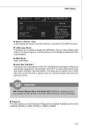
BIOS Setup Device / Vender / Size It will showing the device information that monitors your disk status to predict hard disk failure. Setting to the SATA connector. S.M.A.R.T ...
BIOS Setup Device / Vender / Size It will showing the device information that monitors your disk status to predict hard disk failure. Setting to the SATA connector. S.M.A.R.T ...

User Guide
Page 41
MS-7392 Mainboard System Information Press to enter the sub-menu, and the following screen appears. This sub-menu shows the CPU information, BIOS version and memory status of your system (read only). 3-8
MS-7392 Mainboard System Information Press to enter the sub-menu, and the following screen appears. This sub-menu shows the CPU information, BIOS version and memory status of your system (read only). 3-8

User Guide
Page 42
... This field is able to show the company logo on the bootup screen. Settings are: [Enabled] Shows a still image (logo) on the numeric keypad. Advanced BIOS Features BIOS Setup Full Screen LOGO Display This item enables you to run in APIC mode.
... This field is able to show the company logo on the bootup screen. Settings are: [Enabled] Shows a still image (logo) on the numeric keypad. Advanced BIOS Features BIOS Setup Full Screen LOGO Display This item enables you to run in APIC mode.

User Guide
Page 44
if the system fails to boot from other device. Boot From Other Device Setting the option to [Yes] allows the system to try to load the disk operating system. BIOS Setup Boot Sequence Press to enter the sub-menu and the following screen appears: 1st/ 2nd/ 3rd Boot Device The items allow you to set the first/ second boot device where BIOS attempts to boot from the 1st/ 2nd/ 3rd boot device. 3-11
if the system fails to boot from other device. Boot From Other Device Setting the option to [Yes] allows the system to try to load the disk operating system. BIOS Setup Boot Sequence Press to enter the sub-menu and the following screen appears: 1st/ 2nd/ 3rd Boot Device The items allow you to set the first/ second boot device where BIOS attempts to boot from the 1st/ 2nd/ 3rd boot device. 3-11

User Guide
Page 46
... item allows you to select the parallel port mode. 3-13 PCI IDE BusMaster This item allows you to enable/ disable BIOS to used PCI busmastering for the first serial port. BIOS Setup On-Chip IDE Controller These items allow users to enable or disable the SATA controller. On-Chip SATA Controller These...
... item allows you to select the parallel port mode. 3-13 PCI IDE BusMaster This item allows you to enable/ disable BIOS to used PCI busmastering for the first serial port. BIOS Setup On-Chip IDE Controller These items allow users to enable or disable the SATA controller. On-Chip SATA Controller These...

User Guide
Page 47
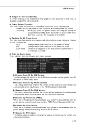
... to restore the system when a "wake up" event occurs. 3-14 If your operating system supports ACPI, such as W indows 2000/ XP, select [Enabled]. If your BIOS supports S3 sleep mode. Settings are available only when your operating system is a low power state.
... to restore the system when a "wake up" event occurs. 3-14 If your operating system supports ACPI, such as W indows 2000/ XP, select [Enabled]. If your BIOS supports S3 sleep mode. Settings are available only when your operating system is a low power state.
User Guide
Page 48
... Alarm The field is used to the status before power failure or interrupt occurred. Wake Up Event Setup Press and the following sub-menu appears. BIOS Setup Suspend Time Out (Minute) If system activity is not detected for the length of time specified in the power on PME (Power Management Event...
... Alarm The field is used to the status before power failure or interrupt occurred. Wake Up Event Setup Press and the following sub-menu appears. BIOS Setup Suspend Time Out (Minute) If system activity is not detected for the length of time specified in the power on PME (Power Management Event...

User Guide
Page 50
BIOS Setup IRQ Resource Setup Press to it signals this by AMIBIOS. IRQ 3/4/5/7/9/10/11/14/15 These items specify the bus where the specified IRQ ... PnP devices. When an I /O are system resources allocated to the onboard PCI IDE, IRQ 9 will interrupt itself and perform the service required by the system BIOS. After receiving the signal, when the operating system is determined by assigning an [Reserved] setting to enter the sub-menu and the following screen appears...
BIOS Setup IRQ Resource Setup Press to it signals this by AMIBIOS. IRQ 3/4/5/7/9/10/11/14/15 These items specify the bus where the specified IRQ ... PnP devices. When an I /O are system resources allocated to the onboard PCI IDE, IRQ 9 will interrupt itself and perform the service required by the system BIOS. After receiving the signal, when the operating system is determined by assigning an [Reserved] setting to enter the sub-menu and the following screen appears...


