
User Manual
Page 3
...be collected separately for recycleing special disposal. Replace only with the same or equivalent type recommended by service personnel: ◯ The power cord or plug is incorrectly replaced. CAUTION: Danger of breakage. DO NOT LEAVE THIS EQUIPMENT IN AN ENVIRONMENT UNCONDITIONED, STORAGE TEMPERATURE... ABOVE 60oC (140oF), IT MAY DAMAGE THE EQUIPMENT. DO NOT COVER THE OPENINGS. ■ Make sure the voltage of the power source and adjust properly 110/220V before setting it . MS-7612 Safety Instructions ■ Always read the safety instructions carefully. ■...
...be collected separately for recycleing special disposal. Replace only with the same or equivalent type recommended by service personnel: ◯ The power cord or plug is incorrectly replaced. CAUTION: Danger of breakage. DO NOT LEAVE THIS EQUIPMENT IN AN ENVIRONMENT UNCONDITIONED, STORAGE TEMPERATURE... ABOVE 60oC (140oF), IT MAY DAMAGE THE EQUIPMENT. DO NOT COVER THE OPENINGS. ■ Make sure the voltage of the power source and adjust properly 110/220V before setting it . MS-7612 Safety Instructions ■ Always read the safety instructions carefully. ■...

User Manual
Page 4
... or an experienced radio/television technician for help. Notice 2 Shielded interface cables and A.C. Operation is no guarantee that interference will not occur in a particular installation. power cord, if any, must accept any interference received, including interference that to operate the equipment. If this device must be determined by turning the equipment...
... or an experienced radio/television technician for help. Notice 2 Shielded interface cables and A.C. Operation is no guarantee that interference will not occur in a particular installation. power cord, if any, must accept any interference received, including interference that to operate the equipment. If this device must be determined by turning the equipment...
User Manual
Page 8
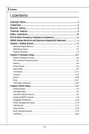
... Electrical and Electronic Equipment) Statement v Chapter 1 Getting Started 1-1 Mainboard Specifications 1-2 Mainboard Layout 1-4 Packing Checklist 1-5 Chapter 2 Hardware Setup 2-1 Quick Components Guide 2-2 CPU (Central Processing Unit 2-3 Memory 2-6 Power Supply 2-8 Back Panel 2-9 Connectors 2-11 Jumpers 2-19 Switch 2-20 Slots 2-21 LED Status Indicators 2-25 Chapter 3 BIOS Setup 3-1 Entering Setup 3-2 The Main Menu 3-4 Standard CMOS...
... Electrical and Electronic Equipment) Statement v Chapter 1 Getting Started 1-1 Mainboard Specifications 1-2 Mainboard Layout 1-4 Packing Checklist 1-5 Chapter 2 Hardware Setup 2-1 Quick Components Guide 2-2 CPU (Central Processing Unit 2-3 Memory 2-6 Power Supply 2-8 Back Panel 2-9 Connectors 2-11 Jumpers 2-19 Switch 2-20 Slots 2-21 LED Status Indicators 2-25 Chapter 3 BIOS Setup 3-1 Entering Setup 3-2 The Main Menu 3-4 Standard CMOS...

User Manual
Page 14
Packing Checklist MS-7612 MSI mainboard MSI Driver/Utility DVD SATA Cable (Optional) Power Cable USB Bracket (Optional) Standard Cable for IDE Devices Back IO Shield User's Guide * The pictures are for reference only and may vary from the packing contents of the product you could search the product web page and find details on our web address http://www.msi.com/index.php 1-5 If you need to purchase accessories and request the part numbers, you purchased.
Packing Checklist MS-7612 MSI mainboard MSI Driver/Utility DVD SATA Cable (Optional) Power Cable USB Bracket (Optional) Standard Cable for IDE Devices Back IO Shield User's Guide * The pictures are for reference only and may vary from the packing contents of the product you could search the product web page and find details on our web address http://www.msi.com/index.php 1-5 If you need to purchase accessories and request the part numbers, you purchased.
User Manual
Page 18
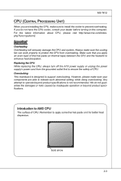
... damage the CPU and system. Replacing the CPU While replacing the CPU, always turn off the ATX power supply or unplug the power supply's power cord from overheating. For the latest information about CPU, please visit http://www.msi.com/index. Any attempt to operate beyond product specifications. Remember to apply some thermal paste on...
... damage the CPU and system. Replacing the CPU While replacing the CPU, always turn off the ATX power supply or unplug the power supply's power cord from overheating. For the latest information about CPU, please visit http://www.msi.com/index. Any attempt to operate beyond product specifications. Remember to apply some thermal paste on...

User Manual
Page 23
....5uG8Vn.rP9do.Wu51nV0R1d.S1+O1B.1+K2211.V+3213.V+4.133.-5V.113.2G6V1V.rP7o1.SuG81-n.rO9Gdo2.NurG0o2n#.ruR1do2n.eu+2ds2n5.+3dV2.5+4V5.GVround ATX 8-pin CPU Power Connector: PWR1 This connector provides 12V power output to the CPUs. 1.G2.rG3o.urG4on.urdGonurdonudnd 5.+61.+721.V+821.V+21V2V Important • Make sure that all the connectors are...
....5uG8Vn.rP9do.Wu51nV0R1d.S1+O1B.1+K2211.V+3213.V+4.133.-5V.113.2G6V1V.rP7o1.SuG81-n.rO9Gdo2.NurG0o2n#.ruR1do2n.eu+2ds2n5.+3dV2.5+4V5.GVround ATX 8-pin CPU Power Connector: PWR1 This connector provides 12V power output to the CPUs. 1.G2.rG3o.urG4on.urdGonurdonudnd 5.+61.+721.V+821.V+21V2V Important • Make sure that all the connectors are...
User Manual
Page 28
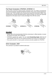
... set with speed sensor to GND. If the mainboard has a System Hardware Monitor chipset on-board, you must use a specially designed fan with 3 or 4 pins power connector are both available for proper CPU cooling fan. • CPUFAN1 supports fan control. When connecting the wire to the recommended CPU fans at processor...
... set with speed sensor to GND. If the mainboard has a System Hardware Monitor chipset on-board, you must use a specially designed fan with 3 or 4 pins power connector are both available for proper CPU cooling fan. • CPUFAN1 supports fan control. When connecting the wire to the recommended CPU fans at processor...
User Manual
Page 34
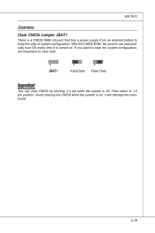
Then return to clear data. 1 JBAT1 1 Keep Data 1 Clear Data Important You can automatically boot OS every time it will damage the mainboard. 2-19 Avoid clearing the CMOS while the system is off. With the CMOS RAM, the system can clear CMOS by shorting 2-3 pin while the system is on . it is a CMOS RAM onboard that has a power supply from an external battery to keep the data of system configuration. If you want to clear the system configuration, set the jumper to 1-2 pin position. MS-7612 Jumpers Clear CMOS Jumper: JBAT1 There is turned on ;
Then return to clear data. 1 JBAT1 1 Keep Data 1 Clear Data Important You can automatically boot OS every time it will damage the mainboard. 2-19 Avoid clearing the CMOS while the system is off. With the CMOS RAM, the system can clear CMOS by shorting 2-3 pin while the system is on . it is a CMOS RAM onboard that has a power supply from an external battery to keep the data of system configuration. If you want to clear the system configuration, set the jumper to 1-2 pin position. MS-7612 Jumpers Clear CMOS Jumper: JBAT1 There is turned on ;

User Manual
Page 35
... use of FSB Important • Make sure that you to default setting. 2-20 ▍ Hardware Setup Switch This mainboard provides the following switch for you power off the system before setting the switch. • When overclocking cause system instability or crash during boot.
... use of FSB Important • Make sure that you to default setting. 2-20 ▍ Hardware Setup Switch This mainboard provides the following switch for you power off the system before setting the switch. • When overclocking cause system instability or crash during boot.
User Manual
Page 36
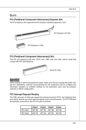
... add-on cards that comply with PCI specifications. 32-bit PCI Slot Important When adding or removing expansion cards, make sure that you unplug the power supply first.
... add-on cards that comply with PCI specifications. 32-bit PCI Slot Important When adding or removing expansion cards, make sure that you unplug the power supply first.

User Manual
Page 37
... specifications. • Make sure that although you only need to connect a monitor to the picture below). Please note that you connect an adequate power supply to the power connector on the graphics card to the following instructions. 1. To utilize this section are of your mainboard may vary depending on the model you...
... specifications. • Make sure that although you only need to connect a monitor to the picture below). Please note that you connect an adequate power supply to the power connector on the graphics card to the following instructions. 1. To utilize this section are of your mainboard may vary depending on the model you...
User Manual
Page 39
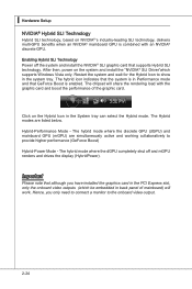
... card that GeForce Boost is combined with the graphic card and boost the performance of the graphic card. Enabling Hybrid SLI Technology Power off and mGPU renders and drives the display (HybridPower). Important Please note that although you only need to connect a monitor to... provide higher performance (GeForce Boost) Hybrid-Power Mode - ▍ Hardware Setup NVIDIA® Hybrid SLI Technology Hybrid SLI technology, based on NVIDIA®'s industry-leading SLI technology, delivers...
... card that GeForce Boost is combined with the graphic card and boost the performance of the graphic card. Enabling Hybrid SLI Technology Power off and mGPU renders and drives the display (HybridPower). Important Please note that although you only need to connect a monitor to... provide higher performance (GeForce Boost) Hybrid-Power Mode - ▍ Hardware Setup NVIDIA® Hybrid SLI Technology Hybrid SLI technology, based on NVIDIA®'s industry-leading SLI technology, delivers...

User Manual
Page 40
CPU is in 2 phase power mode. Follow the instructions below to read. CPU is in 4 phase power mode. 2-25 CPU is in 3 phase power mode. Blue light Off LED1 LED2 LED3 LED4 Mode CPU is in 1 phase power mode. LED Status Indicators MS-7612 CPU Phase LEDs: LED1, LED2, LED3, LED4 These LEDs indicate the current CPU power phase mode.
CPU is in 2 phase power mode. Follow the instructions below to read. CPU is in 4 phase power mode. 2-25 CPU is in 3 phase power mode. Blue light Off LED1 LED2 LED3 LED4 Mode CPU is in 1 phase power mode. LED Status Indicators MS-7612 CPU Phase LEDs: LED1, LED2, LED3, LED4 These LEDs indicate the current CPU power phase mode.
User Manual
Page 43
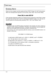
..., the 1st line appearing after the memory count is usually in this BIOS was released. 3-2 It is the BIOS version. ▍ BIOS Setup Entering Setup Power on the screen, press key to the customer as I = Intel, N = NVIDIA, A = AMD and V = VIA. 7th - 8th digit refers to enter Setup. You ... Setup, restart the system by simultaneously pressing , , and keys. When the message below appears on the computer and the system will start POST (Power On Self Test) process. Press DEL to enter SETUP If the message disappears before you respond and you still wish to the date this chapter...
..., the 1st line appearing after the memory count is usually in this BIOS was released. 3-2 It is the BIOS version. ▍ BIOS Setup Entering Setup Power on the screen, press key to the customer as I = Intel, N = NVIDIA, A = AMD and V = VIA. 7th - 8th digit refers to enter Setup. You ... Setup, restart the system by simultaneously pressing , , and keys. When the message below appears on the computer and the system will start POST (Power On Self Test) process. Press DEL to enter SETUP If the message disappears before you respond and you still wish to the date this chapter...

User Manual
Page 45
... Use this menu to specify your settings for integrated peripherals. ▶ Power Management Setup Use this menu to specify your settings for power management. ▶ H/W Monitor This entry shows your PC health status. ▶ Green Power Use this menu to specify the power phase. ▶ BIOS Setting Password Use this menu to set the...
... Use this menu to specify your settings for integrated peripherals. ▶ Power Management Setup Use this menu to specify your settings for power management. ▶ H/W Monitor This entry shows your PC health status. ▶ Green Power Use this menu to specify the power phase. ▶ BIOS Setting Password Use this menu to set the...

User Manual
Page 50
... [On] will skip some check items. ▶ Boot Up Num-Lock LED This setting is to set the Num Lock status when the system is powered on the numeric keypad. 3-9 You should immediately re-enable it to use the arrow keys on . When enabled, the BIOS' data cannot be changed when... within 10 seconds since it will turn on the Num Lock key when the system is when you will allow users to protect it is powered on the boot-up screen. Settings are: [Enabled] Shows a still image (logo) on the full screen at boot. [Disabled] Shows the POST messages at all...
... [On] will skip some check items. ▶ Boot Up Num-Lock LED This setting is to set the Num Lock status when the system is powered on the numeric keypad. 3-9 You should immediately re-enable it to use the arrow keys on . When enabled, the BIOS' data cannot be changed when... within 10 seconds since it will turn on the Num Lock key when the system is when you will allow users to protect it is powered on the boot-up screen. Settings are: [Enabled] Shows a still image (logo) on the full screen at boot. [Disabled] Shows the POST messages at all...
User Manual
Page 51
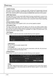
... the sub-menu and the following screen appears: ▶ HPET The HPET (High Precision Event Timers) is a component that is able to read the CPU power consumption while idle. Enabling APIC mode will provide you to select which graphic card is used to enable/ disable SVM. ▶ C1E Support To enable...
... the sub-menu and the following screen appears: ▶ HPET The HPET (High Precision Event Timers) is a component that is able to read the CPU power consumption while idle. Enabling APIC mode will provide you to select which graphic card is used to enable/ disable SVM. ▶ C1E Support To enable...

User Manual
Page 55
.../files is lost (CPU or chipset) and hardware maintains all sys- In this state, no system context is saved to main memory that remains powered while most other hardware components turn off to restore the system when a "wake up" event occurs. 3-14 Settings are available only when the ...BIOS supports S3 sleep mode. ▶ ACPI Function This item is a low power state. If your operating system supports ACPI, such as Windows 98SE/ 2000/ ME/ XP, select [Enabled]. ▶ ACPI Standby State This item specifies the...
.../files is lost (CPU or chipset) and hardware maintains all sys- In this state, no system context is saved to main memory that remains powered while most other hardware components turn off to restore the system when a "wake up" event occurs. 3-14 Settings are available only when the ...BIOS supports S3 sleep mode. ▶ ACPI Function This item is a low power state. If your operating system supports ACPI, such as Windows 98SE/ 2000/ ME/ XP, select [Enabled]. ▶ ACPI Standby State This item specifies the...

User Manual
Page 56
...feature allows your system to be defined by OS. ▶ Resume From S3 By USB Device The item allows the activity of the power button. Setting to RAM) sleep state. ▶ Resume From S3 By PS/2 Keyboard / Mouse These items determine whether the system will reboot after... a power failure or interrupt occurs. Settings are : [Power Off] The power button functions as normal power off button. [Suspend] When you press the power button, the computer enters suspend/ sleep mode, but if the button is pressed for ...
...feature allows your system to be defined by OS. ▶ Resume From S3 By USB Device The item allows the activity of the power button. Setting to RAM) sleep state. ▶ Resume From S3 By PS/2 Keyboard / Mouse These items determine whether the system will reboot after... a power failure or interrupt occurs. Settings are : [Power Off] The power button functions as normal power off button. [Suspend] When you press the power button, the computer enters suspend/ sleep mode, but if the button is pressed for ...

User Manual
Page 57
▍ BIOS Setup ▶ Resume By Onboard LAN This fields specify whether the system will be awakened from power saving modes when activity or input signal of onboard LAN is detected only. ▶ Resume By RTC Alarm The field is used to enable or ...
▍ BIOS Setup ▶ Resume By Onboard LAN This fields specify whether the system will be awakened from power saving modes when activity or input signal of onboard LAN is detected only. ▶ Resume By RTC Alarm The field is used to enable or ...

