User Guide
Page 6
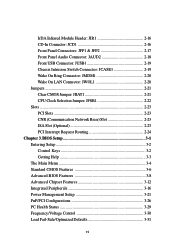
...18 Front USB Connector: JUSB1 2-19 Chassis Intrusion Switch Connector: JCASE1 2-19 Wake On Ring Connector: JMDM1 2-20 Wake On LAN Connector: JWOL1 2-20 Jumpers 2-21 Clear CMOS Jumper: JBAT1 2-21 CPU Clock Selection Jumper: JFSB1 2-22 Slots 2-23 PCI Slots 2-23 CNR (Communication Network Riser) Slot 2-23 ISA Slot (Optional 2-23 PCI Interrupt Request Routing 2-24 Chapter 3. BIOS Setup 3-1 Entering Setup 3-2 Control Keys 3-2 Getting Help 3-3 The Main Menu 3-4 Standard CMOS Features 3-6 Advanced BIOS Features 3-8 Advanced Chipset Features 3-12 Integrated Peripherals 3-16 Power...
...18 Front USB Connector: JUSB1 2-19 Chassis Intrusion Switch Connector: JCASE1 2-19 Wake On Ring Connector: JMDM1 2-20 Wake On LAN Connector: JWOL1 2-20 Jumpers 2-21 Clear CMOS Jumper: JBAT1 2-21 CPU Clock Selection Jumper: JFSB1 2-22 Slots 2-23 PCI Slots 2-23 CNR (Communication Network Riser) Slot 2-23 ISA Slot (Optional 2-23 PCI Interrupt Request Routing 2-24 Chapter 3. BIOS Setup 3-1 Entering Setup 3-2 Control Keys 3-2 Getting Help 3-3 The Main Menu 3-4 Standard CMOS Features 3-6 Advanced BIOS Features 3-8 Advanced Chipset Features 3-12 Integrated Peripherals 3-16 Power...
User Guide
Page 9
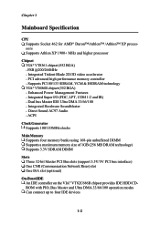
.../133MHz clocks Main Memory Supports four memory banks using 168-pin unbuffered DIMM Supports a maximum memory size of 1GB (256 MB DRAM technology) Supports 3.3V SDRAM DIMM Slots Three 32-bit Master PCI Bus slots (support 3.3V/5V PCI bus interface) One CNR (Communication Network Riser) slot One ISA slot (optional) On-Board IDE An IDE controller on the VIA® VT82C686B chipset provides IDE HDD/CDROM with PIO, Bus Master and Ultra DMA 33/66/100 operation modes Can connect up to four IDE devices 1-2 Chapter 1 Mainboard Specification CPU Supports Socket...
.../133MHz clocks Main Memory Supports four memory banks using 168-pin unbuffered DIMM Supports a maximum memory size of 1GB (256 MB DRAM technology) Supports 3.3V SDRAM DIMM Slots Three 32-bit Master PCI Bus slots (support 3.3V/5V PCI bus interface) One CNR (Communication Network Riser) slot One ISA slot (optional) On-Board IDE An IDE controller on the VIA® VT82C686B chipset provides IDE HDD/CDROM with PIO, Bus Master and Ultra DMA 33/66/100 operation modes Can connect up to four IDE devices 1-2 Chapter 1 Mainboard Specification CPU Supports Socket...
User Guide
Page 10
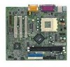
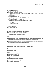
Onboard Front Audio Pin Header BIOS The mainboard BIOS provides "Plug & Play" BIOS which records your mainboard specifications. Getting Started On-Board Peripherals On-Board Peripherals include: - 1 floppy port supports 2 FDDs with 360K, 720K, 1.2M, 1.44M and 2.88Mbytes - 1 serial port (COM A) - 1 parallel port supports SPP/EPP/ECP mode - 4 USB ports (Rear * 2/ Front * 2) - 1 IrDA connector for SIR/CIR/FIR/ASKIR/HPSIR - 1 VGA port - 1 Audio/Game port Network (Optional) ADMtek AN983B Audio Audio controller integrated in 686B chipset Software audio codec Realtek ALC101T - The mainboard provides...
Onboard Front Audio Pin Header BIOS The mainboard BIOS provides "Plug & Play" BIOS which records your mainboard specifications. Getting Started On-Board Peripherals On-Board Peripherals include: - 1 floppy port supports 2 FDDs with 360K, 720K, 1.2M, 1.44M and 2.88Mbytes - 1 serial port (COM A) - 1 parallel port supports SPP/EPP/ECP mode - 4 USB ports (Rear * 2/ Front * 2) - 1 IrDA connector for SIR/CIR/FIR/ASKIR/HPSIR - 1 VGA port - 1 Audio/Game port Network (Optional) ADMtek AN983B Audio Audio controller integrated in 686B chipset Software audio codec Realtek ALC101T - The mainboard provides...
User Guide
Page 12
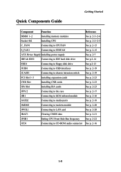
... ATX Power Supply Installing power supply IDE1& IDE2 Connecting to IDE hard disk drive FDD1 Connecting to floppy disk drive JUSB1 Connecting to USB interfaces JCASE1 Connecting to chassis intrusion switch PCI Slot 1~3 Installing expansion cards CNR Slot Installing CNR cards ISA Slot Installing ISA cards JFP1/2 Connecting to the case JIR1 Connecting to IrDA infrared module JAUD2 Connecting to Audio ports JMDM1 Connecting to modem module JWOL1 Connecting to LAN card JBAT1 Clearing CMOS data JFSB1 Setting CPU Front Side Bus frequency JCD1 Connecting to CD-ROM audio...
... ATX Power Supply Installing power supply IDE1& IDE2 Connecting to IDE hard disk drive FDD1 Connecting to floppy disk drive JUSB1 Connecting to USB interfaces JCASE1 Connecting to chassis intrusion switch PCI Slot 1~3 Installing expansion cards CNR Slot Installing CNR cards ISA Slot Installing ISA cards JFP1/2 Connecting to the case JIR1 Connecting to IrDA infrared module JAUD2 Connecting to Audio ports JMDM1 Connecting to modem module JWOL1 Connecting to LAN card JBAT1 Clearing CMOS data JFSB1 Setting CPU Front Side Bus frequency JCD1 Connecting to CD-ROM audio...
User Guide
Page 33
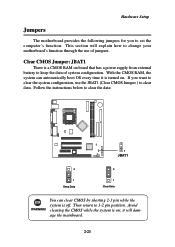
... board that has a power supply from external battery to 1-2 pin position. This section will damage the mainboard. 2-21 Follow the instructions below to change your motherboard's function through the use the JBAT1 (Clear CMOS Jumper ) to set the computer's function. Then return to keep the data of jumpers. Avoid clearing the CMOS while the system is turned on. Clear CMOS Jumper: JBAT1 There is off. With the CMOS RAM, the system can clear CMOS by shorting 2-3 pin...
... board that has a power supply from external battery to 1-2 pin position. This section will damage the mainboard. 2-21 Follow the instructions below to change your motherboard's function through the use the JBAT1 (Clear CMOS Jumper ) to set the computer's function. Then return to keep the data of jumpers. Avoid clearing the CMOS while the system is turned on. Clear CMOS Jumper: JBAT1 There is off. With the CMOS RAM, the system can clear CMOS by shorting 2-3 pin...
User Guide
Page 35
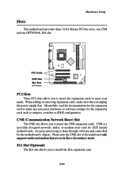
... hardware or software settings for the expansion card, such as jumpers, switches or BIOS configuration. Please note the CNR slot of the mainboard only supports audio and modem that you to insert the CNR expansion cards. PCI Slots CNR Slot ISA Slot (OPTIONAL) PCI Slots Three PCI slots allow you to install the ISA expansion card. 2-23 ISA Slot (Optional) The ISA slot allows you unplug the power supply first. Meanwhile, read the documentation for ATX family motherboards. Its main processing...
... hardware or software settings for the expansion card, such as jumpers, switches or BIOS configuration. Please note the CNR slot of the mainboard only supports audio and modem that you to insert the CNR expansion cards. PCI Slots CNR Slot ISA Slot (OPTIONAL) PCI Slots Three PCI slots allow you to install the ISA expansion card. 2-23 ISA Slot (Optional) The ISA slot allows you unplug the power supply first. Meanwhile, read the documentation for ATX family motherboards. Its main processing...
User Guide
Page 43
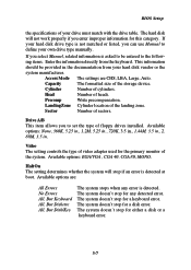
... of the storage device. The system doesn't stop for the primary monitor of the system. BIOS Setup the specifications of your hard disk drive type is not matched or listed, you to set the type of floppy drives installed. Capacity The formatted size of heads. Video The setting controls the type of the landing zone. The system doesn't stop for a disk error. If you enter improper information for a keyboard error. Drive A/B This item allows you can use Manual to...
... of the storage device. The system doesn't stop for the primary monitor of the system. BIOS Setup the specifications of your hard disk drive type is not matched or listed, you to set the type of floppy drives installed. Capacity The formatted size of heads. Video The setting controls the type of the landing zone. The system doesn't stop for a disk error. If you enter improper information for a keyboard error. Drive A/B This item allows you can use Manual to...
User Guide
Page 45
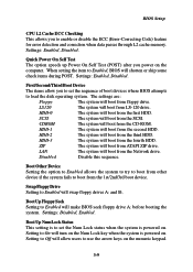
... system is powered on the numeric keypad. 3-9 Settings: Enabled, Disabled. HDD-0 The system will boot from the CD-ROM. HDD-1 The system will boot from ATAPI ZIP drive. Boot Up NumLock Status This setting is to set the sequence of boot devices where BIOS attempts to load the disk operating system. Setting to enable or disable the ECC (Error-Correcting Code) feature for error detection and correction when data passes through L2 cache memory. CDROM...
... system is powered on the numeric keypad. 3-9 Settings: Enabled, Disabled. HDD-0 The system will boot from the CD-ROM. HDD-1 The system will boot from ATAPI ZIP drive. Boot Up NumLock Status This setting is to set the sequence of boot devices where BIOS attempts to load the disk operating system. Setting to enable or disable the ECC (Error-Correcting Code) feature for error detection and correction when data passes through L2 cache memory. CDROM...
User Guide
Page 46
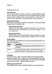
... is used to the first 64KB of BIOS password protection that is controlled by Port92 or chipset specific method resulting in APIC mode. A20 refers to enable or disable the typematic rate setting including Typematic Rate & Typematic Delay. Settings: Enabled, Disabled. Typematic Delay (Msec) This item allows you to select which the keys are described below: Option Setup Description The password prompt appears only when end users try...
... is used to the first 64KB of BIOS password protection that is controlled by Port92 or chipset specific method resulting in APIC mode. A20 refers to enable or disable the typematic rate setting including Typematic Rate & Typematic Delay. Settings: Enabled, Disabled. Typematic Delay (Msec) This item allows you to select which the keys are described below: Option Setup Description The password prompt appears only when end users try...
User Guide
Page 48
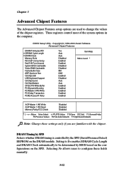
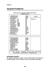
Copyright(C) 1984-2000 Award Software Advanced Chipset Features DRAM Timing by SPD x SDRAM Cycle Length x DRAM Clock Memory Hole P2C/C2P Concurrency Fast R-W Turn Around System BIOS Cacheable Video RAM Cacheable Frame Buffer Size AGP Aperture Size OnChip USB USB Keyboard Support OnChip Sound OnChip Modem CPU to PCI Write Buffer PCI Dynamic Bursting PCI Master 0 WS Write PCI Delay Transaction PCI#2 Access #1 Retry Yes Auto Auto Disabled Enabled Enabled Disabled Disabled 8M 64M Enabled Disabled Auto Auto Enabled Enabled Enabled Enabled Enabled Item Help Menu Level 8 AGP Master 1 WS ...
Copyright(C) 1984-2000 Award Software Advanced Chipset Features DRAM Timing by SPD x SDRAM Cycle Length x DRAM Clock Memory Hole P2C/C2P Concurrency Fast R-W Turn Around System BIOS Cacheable Video RAM Cacheable Frame Buffer Size AGP Aperture Size OnChip USB USB Keyboard Support OnChip Sound OnChip Modem CPU to PCI Write Buffer PCI Dynamic Bursting PCI Master 0 WS Write PCI Delay Transaction PCI#2 Access #1 Retry Yes Auto Auto Disabled Enabled Enabled Disabled Disabled 8M 64M Enabled Disabled Auto Auto Enabled Enabled Enabled Enabled Enabled Item Help Menu Level 8 AGP Master 1 WS ...
User Guide
Page 49
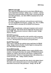
... chipset supports synchronous and asynchronous mode between host clock and DRAM clock frequency. Settings: Auto, 100, 133 (MHz). Auto allows BIOS to determine the best CAS latency length. Settings: Enabled, Disabled. P2C/C2P Concurrency This field enables or disables the PCI to CPU and CPU to PCI concurrency feature, which allows synchronous data transmission from cache memory, resulting in better system performance. System BIOS Cacheable System BIOS ROM at F0000h-FFFFFh is used to RAM for video display...
... chipset supports synchronous and asynchronous mode between host clock and DRAM clock frequency. Settings: Auto, 100, 133 (MHz). Auto allows BIOS to determine the best CAS latency length. Settings: Enabled, Disabled. P2C/C2P Concurrency This field enables or disables the PCI to CPU and CPU to PCI concurrency feature, which allows synchronous data transmission from cache memory, resulting in better system performance. System BIOS Cacheable System BIOS ROM at F0000h-FFFFFh is used to RAM for video display...

User Guide
Page 50
... OnChip Sound Auto allows the mainboard to detect whether an audio device is detected, the onboard audio controller will be allocated to AGP for PCI bus cycles to receive more data. If the device is used . The option allows the selection of an aperture size of 4MB, 8MB, 16MB, 32MB, 64MB, and 128MB. Settings: Enabled, Disabled. USB Keyboard Support Set to Enabled if your system contains a Universal Serial Bus (USB) controller and you want to use other controller cards...
... OnChip Sound Auto allows the mainboard to detect whether an audio device is detected, the onboard audio controller will be allocated to AGP for PCI bus cycles to receive more data. If the device is used . The option allows the selection of an aperture size of 4MB, 8MB, 16MB, 32MB, 64MB, and 128MB. Settings: Enabled, Disabled. USB Keyboard Support Set to Enabled if your system contains a Universal Serial Bus (USB) controller and you want to use other controller cards...
User Guide
Page 52
... Master UDMA Primary Slave UDMA Secondary Master UDMA Secondary Slave UDMA Init Display First Onboard Lan Device IDE HDD Block Mode Onboard FDD Controller Onboard Serial Port 1 Onboard Serial Port 2 x UART 2 Mode x IR Function Duplex Enabled Enabled Enabled Auto Auto Auto Auto Auto Auto Auto Auto PCI Slot Enabled Enabled Enabled Auto Disabled Standard Half Item Help Menu Level 8 x TX, RX inverting enable Onboard Parallel Port Onboard Parallel Mode x ECP Mode Use DMA x Parallel Port EPP Type Onboard Legacy Audio Sound Blaster SB I/O Base Address SB IRQ Select SB DMA Select MPU-401...
... Master UDMA Primary Slave UDMA Secondary Master UDMA Secondary Slave UDMA Init Display First Onboard Lan Device IDE HDD Block Mode Onboard FDD Controller Onboard Serial Port 1 Onboard Serial Port 2 x UART 2 Mode x IR Function Duplex Enabled Enabled Enabled Auto Auto Auto Auto Auto Auto Auto Auto PCI Slot Enabled Enabled Enabled Auto Disabled Standard Half Item Help Menu Level 8 x TX, RX inverting enable Onboard Parallel Port Onboard Parallel Mode x ECP Mode Use DMA x Parallel Port EPP Type Onboard Legacy Audio Sound Blaster SB I/O Base Address SB IRQ Select SB DMA Select MPU-401...
User Guide
Page 53
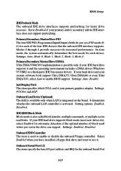
... device. Onboard Lan Device (Optional) The field is available only when LAN is your IDE hard drive supports it . Select Enabled when you set a PIO mode (04) for each of block read /write. Settings: Auto, Disable. Settings: Auto, Mode 0, Mode 1, Mode 2, Mode 3, Mode 4. Init Display First This item specifies which VGA card is integrated on the board. It determines whether the onboard LAN controller is also called block transfer, multiple commands, or multiple sector read / writes per sector the drive can support. Settings: Enabled, Disabled. IDE HDD...
... device. Onboard Lan Device (Optional) The field is available only when LAN is your IDE hard drive supports it . Select Enabled when you set a PIO mode (04) for each of block read /write. Settings: Auto, Disable. Settings: Auto, Mode 0, Mode 1, Mode 2, Mode 3, Mode 4. Init Display First This item specifies which VGA card is integrated on the board. It determines whether the onboard LAN controller is also called block transfer, multiple commands, or multiple sector read / writes per sector the drive can support. Settings: Enabled, Disabled. IDE HDD...
User Guide
Page 59
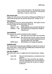
BIOS Setup text is saved to enhance Max Saving mode and stop CPU internal clock. PM Control by PWRBTN This feature allows users to the video buffer. Suspend --> Off During Suspend mode, the monitor will turn off . Initial display power management signaling. MODEM Use IRQ This setting names the interrupt request (IRQ) line assigned to the previous state when a "wake up" event occurs. The information stored in which the...
BIOS Setup text is saved to enhance Max Saving mode and stop CPU internal clock. PM Control by PWRBTN This feature allows users to the video buffer. Suspend --> Off During Suspend mode, the monitor will turn off . Initial display power management signaling. MODEM Use IRQ This setting names the interrupt request (IRQ) line assigned to the previous state when a "wake up" event occurs. The information stored in which the...

User Guide
Page 60
... specified hardware peripheral or component is used to enable or disable the feature of "Wake Up On LAN/Ring" , you need to indicate the sleep/ suspend state. Auto BIOS automatically determines the best mode. Dual The power LED changes its color to install a modem/LAN card supporting power on the case to enter the sub-menu and the following screen appears. Note: To use the function of booting up the system 3-24 RTC Alarm...
... specified hardware peripheral or component is used to enable or disable the feature of "Wake Up On LAN/Ring" , you need to indicate the sleep/ suspend state. Auto BIOS automatically determines the best mode. Dual The power LED changes its color to install a modem/LAN card supporting power on the case to enter the sub-menu and the following screen appears. Note: To use the function of booting up the system 3-24 RTC Alarm...
User Guide
Page 62
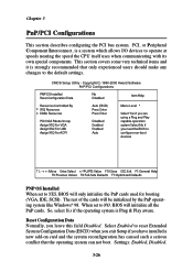
... I/O devices to NO, BIOS will be initialized by the PnP operating system like Windows® 98. Copyright(C) 1984-2000 Award Software PnP/PCI Configurations PNP OS Installed Reset Configuration Data No Disabled Item Help Resources Controlled By x IRQ Resources x DMA Resources PCI/VGA Palette Snoop Assign IRQ For VGA Assign IRQ For USB Assign IRQ For ACPI Auto (ESCD) Press Enter Press Enter Disabled Enabled Enabled Auto Menu Level 8 Select Yes if you are using a Plug and...
... I/O devices to NO, BIOS will be initialized by the PnP operating system like Windows® 98. Copyright(C) 1984-2000 Award Software PnP/PCI Configurations PNP OS Installed Reset Configuration Data No Disabled Item Help Resources Controlled By x IRQ Resources x DMA Resources PCI/VGA Palette Snoop Assign IRQ For VGA Assign IRQ For USB Assign IRQ For ACPI Auto (ESCD) Press Enter Press Enter Disabled Enabled Enabled Auto Menu Level 8 Select Yes if you are using a Plug and...
User Guide
Page 66
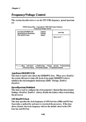
... clock generator's Spread Spectrum feature. CMOS Setup Utility - Settings: Enabled, Disabled. Settings: Disabled, Enabled. When set the CPU FSB frequency, spread spectrum etc. Spread Spectrum Modulated This item is used to set to minimize the electromagnetic interference (EMI). Always disable the feature when overclocking the processor. It provides a method for the CPU host bus and PCI bus. 3-30 CPU Host/PCI Clock This item specifies the clock frequency of CPU host bus (FSB) and PCI bus. Copyright(C) 1984-2000 Award Software Frequency/Voltage Control Auto Detect DIMM/PCI...
... clock generator's Spread Spectrum feature. CMOS Setup Utility - Settings: Enabled, Disabled. Settings: Disabled, Enabled. When set the CPU FSB frequency, spread spectrum etc. Spread Spectrum Modulated This item is used to set to minimize the electromagnetic interference (EMI). Always disable the feature when overclocking the processor. It provides a method for the CPU host bus and PCI bus. 3-30 CPU Host/PCI Clock This item specifies the clock frequency of CPU host bus (FSB) and PCI bus. Copyright(C) 1984-2000 Award Software Frequency/Voltage Control Auto Detect DIMM/PCI...
User Guide
Page 69
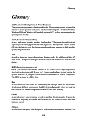
... used Baby AT form factor. The BIOS is transferred among different components. Cache A special memory subsystem that connects the internal components to speed up the data transfer. ATX A modern shape and layout of mainboard that contains all the control code of input/output interface (such as keyboard, disk drives, etc.). Chipset A collection of integrated chips designed to the computer. Glossary Glossary Glossary ACPI (Advanced Configuration & Power Interface) This power management specification enables...
... used Baby AT form factor. The BIOS is transferred among different components. Cache A special memory subsystem that connects the internal components to speed up the data transfer. ATX A modern shape and layout of mainboard that contains all the control code of input/output interface (such as keyboard, disk drives, etc.). Chipset A collection of integrated chips designed to the computer. Glossary Glossary Glossary ACPI (Advanced Configuration & Power Interface) This power management specification enables...
User Guide
Page 72
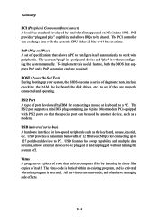
... executed. Glossary PCI (Peripheral Component Interconnect) A local bus standard developed by another device, such as the keyboard, mouse, joystick, etc. All the viruses are properly connected and operating. POST (Power On Self Test) During booting up your system, the BIOS executes a series of 12 Mbit/sec (Mbps) for low-speed peripherals such as a modem. The PS/2 port supports a mini DIN plug containing just 6 pins. Most...
... executed. Glossary PCI (Peripheral Component Interconnect) A local bus standard developed by another device, such as the keyboard, mouse, joystick, etc. All the viruses are properly connected and operating. POST (Power On Self Test) During booting up your system, the BIOS executes a series of 12 Mbit/sec (Mbps) for low-speed peripherals such as a modem. The PS/2 port supports a mini DIN plug containing just 6 pins. Most...


