
User Manual
Page 6
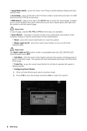
.... 6 BIOS Setup Press F10 to save it provides 4 function modes to enter the search page. It allows you to turn on/ off - press the reset/ smart button for all the onboard LEDs. ⚠ Important The Mystic Light on the motherboard. ▪ Reset - press the reset/ smart button to search by the smart button on / off function mode is unavailable when the LED_SW1 (EZ LED Control) switch turns OFF. ▪ Safe Boot - The system will boot with default...
.... 6 BIOS Setup Press F10 to save it provides 4 function modes to enter the search page. It allows you to turn on/ off - press the reset/ smart button for all the onboard LEDs. ⚠ Important The Mystic Light on the motherboard. ▪ Reset - press the reset/ smart button to search by the smart button on / off function mode is unavailable when the LED_SW1 (EZ LED Control) switch turns OFF. ▪ Safe Boot - The system will boot with default...
User Manual
Page 7
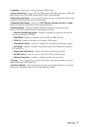
... temperature, MB/ CPU type, memory size, CPU/ DDR voltage, BIOS version and build date. ∙ Boot device priority bar - The button shows ON after enableing the function . ▪ CPU Fan Fail Warning Control - enables or disables the Intel VMD for RAID function. ▪ fTPM 2.0 - ∙ Language - enables or disables the system power consumption according to change the boot priority. enables or disable the HD audio controller. ∙ M-Flash - The boot priority from high to low is left to update BIOS with a USB flash drive. ∙ Hardware Monitor...
... temperature, MB/ CPU type, memory size, CPU/ DDR voltage, BIOS version and build date. ∙ Boot device priority bar - The button shows ON after enableing the function . ▪ CPU Fan Fail Warning Control - enables or disables the Intel VMD for RAID function. ▪ fTPM 2.0 - ∙ Language - enables or disables the system power consumption according to change the boot priority. enables or disable the HD audio controller. ∙ M-Flash - The boot priority from high to low is left to update BIOS with a USB flash drive. ∙ Hardware Monitor...
User Manual
Page 17
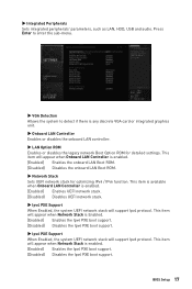
... any discrete VGA card or integrated graphics unit. ▶ Onboard LAN Controller Enables or disables the onboard LAN controller. ▶ LAN Option ROM Enables or disables the legacy network Boot Option ROM for optimizing IPv4 / IPv6 function. This item will support Ipv6 protocol. Press Enter to enter the sub-menu. ▶ VGA Detection Allows the system to detect if there is enabled. [Enabled] Enables the Ipv6 PXE boot support. [Disabled] Disables the Ipv6 PXE boot support. ▶ Integrated Peripherals Sets integrated peripherals' parameters, such as LAN, HDD, USB and audio.
... any discrete VGA card or integrated graphics unit. ▶ Onboard LAN Controller Enables or disables the onboard LAN controller. ▶ LAN Option ROM Enables or disables the legacy network Boot Option ROM for optimizing IPv4 / IPv6 function. This item will support Ipv6 protocol. Press Enter to enter the sub-menu. ▶ VGA Detection Allows the system to detect if there is enabled. [Enabled] Enables the Ipv6 PXE boot support. [Disabled] Disables the Ipv6 PXE boot support. ▶ Integrated Peripherals Sets integrated peripherals' parameters, such as LAN, HDD, USB and audio.
User Manual
Page 20
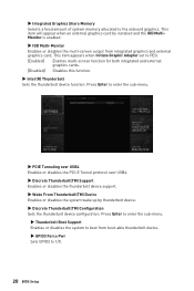
... memory allocated to 1/0. 20 BIOS Setup Press Enter to enter the sub-menu. ▶ Thunderbolt Boot Support Enables or disables the system to boot from integrated graphics and external graphics card. This item appears when Initiate Graphic Adapter set to enter the sub-menu. ▶ PCIE Tunneling over USB4 Enables or disables the PCI-E Tunnel protocol over USB4. ▶ Discrete Thunderbolt(TM) Support Enables or disables the thunderbolt device support. ▶ Wake From Thunderbolt(TM) Device Enables or disables the system wake...
... memory allocated to 1/0. 20 BIOS Setup Press Enter to enter the sub-menu. ▶ Thunderbolt Boot Support Enables or disables the system to boot from integrated graphics and external graphics card. This item appears when Initiate Graphic Adapter set to enter the sub-menu. ▶ PCIE Tunneling over USB4 Enables or disables the PCI-E Tunnel protocol over USB4. ▶ Discrete Thunderbolt(TM) Support Enables or disables the thunderbolt device support. ▶ Wake From Thunderbolt(TM) Device Enables or disables the system wake...

User Manual
Page 22
... USB support. [Enabled] Enables the USB support under legacy mode. ▶ USB Port Control Enables or disables the individual USB ports of the motherboard. Press Enter to enter the sub-menu. ▶ Super IO Configuration Sets system Super I/O chip parameters including LPT and COM ports. If set to enter the submenu. ▶ Serial (COM) Port 0/1 Enables or disables serial (COM) port 0/1. ▶ Serial (COM) Port 0/1 Settings Sets serial (COM) port 0/1. ▶ USB Configuration Sets the onboard USB controller and device function. Press Enter to enter the submenu. 22 BIOS Setup...
... USB support. [Enabled] Enables the USB support under legacy mode. ▶ USB Port Control Enables or disables the individual USB ports of the motherboard. Press Enter to enter the sub-menu. ▶ Super IO Configuration Sets system Super I/O chip parameters including LPT and COM ports. If set to enter the submenu. ▶ Serial (COM) Port 0/1 Enables or disables serial (COM) port 0/1. ▶ Serial (COM) Port 0/1 Settings Sets serial (COM) port 0/1. ▶ USB Configuration Sets the onboard USB controller and device function. Press Enter to enter the submenu. 22 BIOS Setup...

User Manual
Page 23
... Capability Port mode + Enhanced Parallel Port-1.9/ 1.7 mode. ▶ Power Management Setup Sets system Power Management of ErP and AC Power Loss behaviors. If set to Auto, BIOS will not support S4 & S5 wake up by USB, PCI and PCIe devices. [Disabled] Disables this function. ▶ Restore after AC Power Loss Sets the system behaviors while encountering the AC power loss. [Power Off] Leaves the system in power off state after restoring AC power. [Power On] Boot up the...
... Capability Port mode + Enhanced Parallel Port-1.9/ 1.7 mode. ▶ Power Management Setup Sets system Power Management of ErP and AC Power Loss behaviors. If set to Auto, BIOS will not support S4 & S5 wake up by USB, PCI and PCIe devices. [Disabled] Disables this function. ▶ Restore after AC Power Loss Sets the system behaviors while encountering the AC power loss. [Power Off] Leaves the system in power off state after restoring AC power. [Power On] Boot up the...

User Manual
Page 24
... USB Device is set wake up behaviors for different sleep modes. If Resume By RTC Alarm is disabled. ▶ BIOS CSM/UEFI Mode Select CSM (Compatibility Support Module) or UEFI mode to [Enabled], the system will be defined by OS. ▶ Resume By RTC Alarm Disables or enables the system wake up by RTC Alarm. [Enabled] Enables the system to select the date & time settings). 24 BIOS Setup Press Enter to enter the sub-menu. ▶ Wake...
... USB Device is set wake up behaviors for different sleep modes. If Resume By RTC Alarm is disabled. ▶ BIOS CSM/UEFI Mode Select CSM (Compatibility Support Module) or UEFI mode to [Enabled], the system will be defined by OS. ▶ Resume By RTC Alarm Disables or enables the system wake up by RTC Alarm. [Enabled] Enables the system to select the date & time settings). 24 BIOS Setup Press Enter to enter the sub-menu. ▶ Wake...
User Manual
Page 25
BIOS Setup 25 ▶ Resume By PCI/ PCI-E/ Networking Device Enables or disables the wake up function of installed PCI/ PCI-E expansion cards, integrated LAN controllers, onboard WiFi or USB devices which are supported by third party integrated chips. [Enabled] Enables the system to be awakened from the power saving modes when activity or input signal of PCI/ PCIe/ LAN/ WiFi device is detected. [Disabled] Disables this function. ▶ Resume By Intel Onboard LAN Enables or disables the system wake up by Onboard Intel LAN. [Enabled] Enables the system to...
BIOS Setup 25 ▶ Resume By PCI/ PCI-E/ Networking Device Enables or disables the wake up function of installed PCI/ PCI-E expansion cards, integrated LAN controllers, onboard WiFi or USB devices which are supported by third party integrated chips. [Enabled] Enables the system to be awakened from the power saving modes when activity or input signal of PCI/ PCIe/ LAN/ WiFi device is detected. [Disabled] Disables this function. ▶ Resume By Intel Onboard LAN Enables or disables the system wake up by Onboard Intel LAN. [Enabled] Enables the system to...
User Manual
Page 26
... according LED color of SSD will appear when Network Stack is enable. Boot Sets the sequence of the ethernet controller parameter. This item will be downloaded automatically through Windows Update after enabling Secure Erase+. ▶ MSI Driver Utility Installer Enables or disables the MSI driver utility support. Please note that data of the M.2 XPANDER-Z fan. Secure Erase+ is the best way to Auto, BIOS will appear when Network Stack is enabled. ▶ Intel ( R ) Ethernet Connection I219...
... according LED color of SSD will appear when Network Stack is enable. Boot Sets the sequence of the ethernet controller parameter. This item will be downloaded automatically through Windows Update after enabling Secure Erase+. ▶ MSI Driver Utility Installer Enables or disables the MSI driver utility support. Please note that data of the M.2 XPANDER-Z fan. Secure Erase+ is the best way to Auto, BIOS will appear when Network Stack is enabled. ▶ Intel ( R ) Ethernet Connection I219...
User Manual
Page 27
... be available when MSI Fast Boot is disabled. ▶ Boot Option #1/ #2/ #3/ #4/ #5/ #6/ #7 These items specify the boot device priority sequence. ▶ UEFI USB Key Drivers BBS Priorities This item is off (S5 state). Fix the Help information block on the screen. ▶ POST Beep Enables or disables the beep sound during system POST. ▶ MSI Fast Boot MSI Fast Boot is booting. ▶ Info Block effect Sets to apply the sliding effect when entering the Graphical Setup Engine (GSE...
... be available when MSI Fast Boot is disabled. ▶ Boot Option #1/ #2/ #3/ #4/ #5/ #6/ #7 These items specify the boot device priority sequence. ▶ UEFI USB Key Drivers BBS Priorities This item is off (S5 state). Fix the Help information block on the screen. ▶ POST Beep Enables or disables the beep sound during system POST. ▶ MSI Fast Boot MSI Fast Boot is booting. ▶ Info Block effect Sets to apply the sliding effect when entering the Graphical Setup Engine (GSE...
User Manual
Page 30
... BIOS Setup The settings will automatically load the secure keys from BIOS. [Custom] Allows user to configure the secure boot settings and manually load the secure keys. ▶ Enroll all Factory Default keys Allows you to install all the Secure Boot keys(PK,KEK,db,dbt,dbx). The settings will be applied after reboot or at the next reboot. ▶ Chassis Intrusion Configuration Press Enter to enter the sub-menu. ▶ Chassis Intrusion Enables or disables recording...
... BIOS Setup The settings will automatically load the secure keys from BIOS. [Custom] Allows user to configure the secure boot settings and manually load the secure keys. ▶ Enroll all Factory Default keys Allows you to install all the Secure Boot keys(PK,KEK,db,dbt,dbx). The settings will be applied after reboot or at the next reboot. ▶ Chassis Intrusion Configuration Press Enter to enter the sub-menu. ▶ Chassis Intrusion Enables or disables recording...
User Manual
Page 41
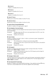
... thermal monitor function to select a CPU C-state level for power-saving in halt state. It can optimize energy efficiency. This item is idle. C-state is enabled. ▶ Intel Speed Shift Technology Enables or disables Intel Speed Shift Technology. The options of C-state depend on the installed CPU. BIOS Setup 41 This item appears when Intel C-State is a processor power management technology defined by ACPI. [Auto] This setting will be configured automatically by BIOS. [Enabled...
... thermal monitor function to select a CPU C-state level for power-saving in halt state. It can optimize energy efficiency. This item is idle. C-state is enabled. ▶ Intel Speed Shift Technology Enables or disables Intel Speed Shift Technology. The options of C-state depend on the installed CPU. BIOS Setup 41 This item appears when Intel C-State is a processor power management technology defined by ACPI. [Auto] This setting will be configured automatically by BIOS. [Enabled...
User Manual
Page 46
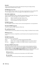
... DRAM gear type for respective memory channel. ▶ Advanced DRAM Configuration Press Enter to enter the sub-menu. The system may enhance memory overclocking ability. 46 BIOS Setup It can set the memory timing for each/ all memory channel. [UnLink] Allows user to load the default settings.) ▶ Memory Force It allows showing the memory force illustration on the installed CPU. If it occurs, please clear the CMOS data and restore the default settings. (Refer to the Clear CMOS jumper/ button section in motherboard user guide...
... DRAM gear type for respective memory channel. ▶ Advanced DRAM Configuration Press Enter to enter the sub-menu. The system may enhance memory overclocking ability. 46 BIOS Setup It can set the memory timing for each/ all memory channel. [UnLink] Allows user to load the default settings.) ▶ Memory Force It allows showing the memory force illustration on the installed CPU. If it occurs, please clear the CMOS data and restore the default settings. (Refer to the Clear CMOS jumper/ button section in motherboard user guide...
User Manual
Page 65
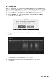
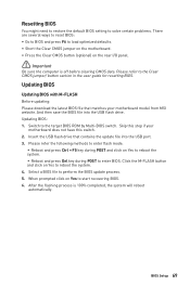
... perform the BIOS update process. 5. BIOS Setup 65 The system will enter the flash mode and a file selection menu will be prompted. Select a BIOS file to update BIOS. 1. Click on Yes to update BIOS with a USB flash drive. After the flashing process is 100% completed, the system will reboot automatically. Insert the USB flash drive that matches your USB flash drive. Please download the latest BIOS file that contains the update file into your motherboard model from MSI website, save the BIOS file into the...
... perform the BIOS update process. 5. BIOS Setup 65 The system will enter the flash mode and a file selection menu will be prompted. Select a BIOS file to update BIOS. 1. Click on Yes to update BIOS with a USB flash drive. After the flashing process is 100% completed, the system will reboot automatically. Insert the USB flash drive that matches your USB flash drive. Please download the latest BIOS file that contains the update file into your motherboard model from MSI website, save the BIOS file into the...
User Manual
Page 69
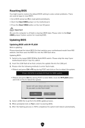
... motherboard model from MSI website. Select a BIOS file to the Clear CMOS jumper/ button section in the user guide for resetting BIOS. Insert the USB flash drive that matches your motherboard does not have this switch. 2. Please refer to perform the BIOS update process. 5. Resetting BIOS You might need to restore the default BIOS setting to solve certain problems. There are several ways to reset BIOS: ∙ Go to BIOS and press F6 to load optimized defaults. ∙ Short the Clear CMOS jumper on the motherboard...
... motherboard model from MSI website. Select a BIOS file to the Clear CMOS jumper/ button section in the user guide for resetting BIOS. Insert the USB flash drive that matches your motherboard does not have this switch. 2. Please refer to perform the BIOS update process. 5. Resetting BIOS You might need to restore the default BIOS setting to solve certain problems. There are several ways to reset BIOS: ∙ Go to BIOS and press F6 to load optimized defaults. ∙ Short the Clear CMOS jumper on the motherboard...
User Manual 1
Page 2
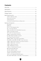
... Panel Connectors 24 LAN Port LED Status Table 25 Audio Jacks Connection 26 Installing Antennas 28 Connecting Thunderbolt Devices via Daisy-chain 29 Overview of Components 30 CPU Socket...31 DIMM Slots...32 PCI_E1~3: PCIe Expansion Slots 33 M2_1~5: M.2 Slots (Key M 34 SATA_5~8 & SATA_A1~A2: SATA 6Gb/s Connectors 43 JAUD1: Front Audio Connector 43 JFP1, JFP2: Front Panel Connectors 44 JDASH1: Tuning Controller Connector 45 W_FLOW1: Water Flow Meter Connector 45 JCI1: Chassis Intrusion Connector 46 POWER1, RESET1: Power Button, Reset Button...
... Panel Connectors 24 LAN Port LED Status Table 25 Audio Jacks Connection 26 Installing Antennas 28 Connecting Thunderbolt Devices via Daisy-chain 29 Overview of Components 30 CPU Socket...31 DIMM Slots...32 PCI_E1~3: PCIe Expansion Slots 33 M2_1~5: M.2 Slots (Key M 34 SATA_5~8 & SATA_A1~A2: SATA 6Gb/s Connectors 43 JAUD1: Front Audio Connector 43 JFP1, JFP2: Front Panel Connectors 44 JDASH1: Tuning Controller Connector 45 W_FLOW1: Water Flow Meter Connector 45 JCI1: Chassis Intrusion Connector 46 POWER1, RESET1: Power Button, Reset Button...
User Manual 1
Page 16
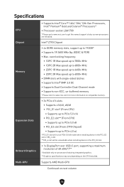
... processors featuring integrated graphics. ** Graphics specifications may vary depending on the CPU installed. Specifications CPU Chipset Memory Expansion Slots Onboard Graphics ∙ Supports Intel® Core™ 14th/ 13th/ 12th Gen Processors, Intel® Pentium® Gold and Celeron® Processors* ∙ Processor socket LGA1700 * Please go to www.msi.com to 192GB* ∙ Supports 1R 5600 MHz (by JEDEC & POR) ∙ Max. Multi-GPU Supports AMD Multi-GPU Continued on compatible memory. ∙ 3x PCIe x16 slots...
... processors featuring integrated graphics. ** Graphics specifications may vary depending on the CPU installed. Specifications CPU Chipset Memory Expansion Slots Onboard Graphics ∙ Supports Intel® Core™ 14th/ 13th/ 12th Gen Processors, Intel® Pentium® Gold and Celeron® Processors* ∙ Processor socket LGA1700 * Please go to www.msi.com to 192GB* ∙ Supports 1R 5600 MHz (by JEDEC & POR) ∙ Max. Multi-GPU Supports AMD Multi-GPU Continued on compatible memory. ∙ 3x PCIe x16 slots...
User Manual 1
Page 62
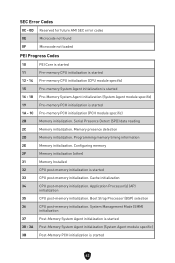
.... Serial Presence Detect (SPD) data reading Memory initialization. Application Processor(s) (AP) initialization CPU post-memory initialization. Programming memory timing information Memory initialization. Cache initialization CPU post-memory initialization. Memory presence detection Memory initialization. SEC Error Codes 0C - 0D Reserved for future AMI SEC error codes 0E Microcode not found 0F Microcode not loaded PEI Progress Codes 10 11 12 - 14 15 16 - 18 PEI Core is started Pre-memory CPU initialization is started Pre-memory CPU...
.... Serial Presence Detect (SPD) data reading Memory initialization. Application Processor(s) (AP) initialization CPU post-memory initialization. Programming memory timing information Memory initialization. Cache initialization CPU post-memory initialization. Memory presence detection Memory initialization. SEC Error Codes 0C - 0D Reserved for future AMI SEC error codes 0E Microcode not found 0F Microcode not loaded PEI Progress Codes 10 11 12 - 14 15 16 - 18 PEI Core is started Pre-memory CPU initialization is started Pre-memory CPU...
User Manual 1
Page 65
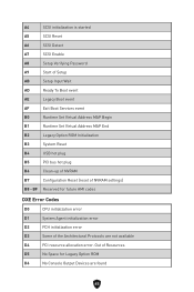
... Enable A8 Setup Verifying Password A9 Start of Setup AB Setup Input Wait AD Ready To Boot event AE Legacy Boot event AF Exit Boot Services event B0 Runtime Set Virtual Address MAP Begin B1 Runtime Set Virtual Address MAP End B2 Legacy Option ROM Initialization B3 System Reset B4 USB hot plug B5 PCI bus hot plug B6 Clean-up of NVRAM B7 Configuration Reset (reset of the Architectural Protocols are found 65 BF Reserved for Legacy Option ROM...
... Enable A8 Setup Verifying Password A9 Start of Setup AB Setup Input Wait AD Ready To Boot event AE Legacy Boot event AF Exit Boot Services event B0 Runtime Set Virtual Address MAP Begin B1 Runtime Set Virtual Address MAP End B2 Legacy Option ROM Initialization B3 System Reset B4 USB hot plug B5 PCI bus hot plug B6 Clean-up of NVRAM B7 Configuration Reset (reset of the Architectural Protocols are found 65 BF Reserved for Legacy Option ROM...
User Manual 1
Page 74
... USB flash drive that matches your motherboard doesn't has this step if your motherboard model from MSI website. When prompted click on Yes to perform the BIOS update process. 5. Select a BIOS file to start recovering BIOS. 6. Updating BIOS: 1. And then save the BIOS file into the USB port. 3. After the flashing process is off before clearing CMOS data. Resetting BIOS You might need to restore the default BIOS setting to solve certain problems. There are several ways to reset BIOS...
... USB flash drive that matches your motherboard doesn't has this step if your motherboard model from MSI website. When prompted click on Yes to perform the BIOS update process. 5. Select a BIOS file to start recovering BIOS. 6. Updating BIOS: 1. And then save the BIOS file into the USB port. 3. After the flashing process is off before clearing CMOS data. Resetting BIOS You might need to restore the default BIOS setting to solve certain problems. There are several ways to reset BIOS...


