User Guide
Page 13
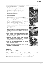
... lever lightly onto the load plate, and then secure the lever with pure vertical motion and reinstall. 8. Press the four hooks down the CPU in BIOS. * Whenever CPU is seated well into the holes of socket reveal. 4. Finally, attach the CPU Fan cable to fasten the cooler. Lift the load ... the socket pin. 2. Before you purchase. 13 Remove the cap from damage. After confirming the CPU direction for demonstration of the CPU/cooler installation only. MS-7529 Follow the steps below to grasp on the edge of the CPU base. Be sure to install the CPU & cooler correctly. If not, take out...
... lever lightly onto the load plate, and then secure the lever with pure vertical motion and reinstall. 8. Press the four hooks down the CPU in BIOS. * Whenever CPU is seated well into the holes of socket reveal. 4. Finally, attach the CPU Fan cable to fasten the cooler. Lift the load ... the socket pin. 2. Before you purchase. 13 Remove the cap from damage. After confirming the CPU direction for demonstration of the CPU/cooler installation only. MS-7529 Follow the steps below to grasp on the edge of the CPU base. Be sure to install the CPU & cooler correctly. If not, take out...
User Guide
Page 19
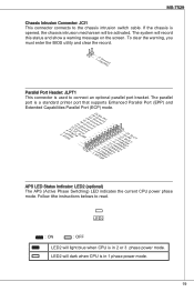
.... If the chassis is in 1 phase power mode. 19 The system will be activated. MS-7529 Chassis Intrusion Connector: JCI1 This connector connects to connect an optional parallel port bracket. To clear the warning, you must enter the BIOS utility and clear the record. 1.C2.IGNTroRuUnd Parallel Port Header: JLPT1 This connector is...
.... If the chassis is in 1 phase power mode. 19 The system will be activated. MS-7529 Chassis Intrusion Connector: JCI1 This connector connects to connect an optional parallel port bracket. To clear the warning, you must enter the BIOS utility and clear the record. 1.C2.IGNTroRuUnd Parallel Port Header: JLPT1 This connector is...
User Guide
Page 21
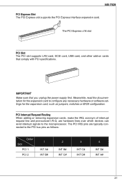
..., acronym of interrupt request line and pronounced I-R-Q, are typically connected to the PCI bus pins as jumpers, switches or BIOS configuration. Meanwhile, read the documentation for the expansion card to the microprocessor. MS-7529 PCI Express Slot The PCI Express slot supports the PCI Express interface expansion card. Important Make sure that comply...
..., acronym of interrupt request line and pronounced I-R-Q, are typically connected to the PCI bus pins as jumpers, switches or BIOS configuration. Meanwhile, read the documentation for the expansion card to the microprocessor. MS-7529 PCI Express Slot The PCI Express slot supports the PCI Express interface expansion card. Important Make sure that comply...
User Guide
Page 23
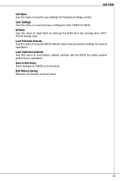
... Setup Save changes to ) storage drive (FAT/ FAT32 format only). Load Optimized Defaults Use this menu to load factory default settings into the BIOS for system operations. MS-7529 Cell Menu Use this menu to specify your settings to/ from (to CMOS and exit setup. Exit Without Saving Abandon all changes and exit...
... Setup Save changes to ) storage drive (FAT/ FAT32 format only). Load Optimized Defaults Use this menu to load factory default settings into the BIOS for system operations. MS-7529 Cell Menu Use this menu to specify your settings to/ from (to CMOS and exit setup. Exit Without Saving Abandon all changes and exit...
User Guide
Page 25
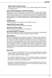
...in clock speed which may just cause your overclocked processor to minimize the electromagnetic interference (EMI). MS-7529 DIMM1~2 Memory SPD Information Press to adjust the PCI-E frequency. FSB/DRAM Ratio This item ... reduced, and the system will become less stable. Read-only. Spread Spectrum When the motherboard's clock generator pulses, the extreme values (spikes) of installed memory. The Spread Spectrum function...to be determined by EMI, select the value of the pulses are plagued by BIOS based on the configurations on the SPD (Serial Presence Detect) EEPROM on the DRAM module. ...
...in clock speed which may just cause your overclocked processor to minimize the electromagnetic interference (EMI). MS-7529 DIMM1~2 Memory SPD Information Press to adjust the PCI-E frequency. FSB/DRAM Ratio This item ... reduced, and the system will become less stable. Read-only. Spread Spectrum When the motherboard's clock generator pulses, the extreme values (spikes) of installed memory. The Spread Spectrum function...to be determined by EMI, select the value of the pulses are plagued by BIOS based on the configurations on the SPD (Serial Presence Detect) EEPROM on the DRAM module. ...
User Guide
Page 41
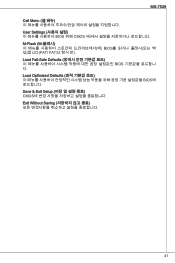
MS-7529 Cell Menu User Settings BIOS 위해 CMOS M-Flash (M BIOS FAT/ FAT32 Load Fail-Safe Defaults BIOS Load Optimized Defaults BIOS Save & Exit Setup CMOS Exit Without Saving 41
MS-7529 Cell Menu User Settings BIOS 위해 CMOS M-Flash (M BIOS FAT/ FAT32 Load Fail-Safe Defaults BIOS Load Optimized Defaults BIOS Save & Exit Setup CMOS Exit Without Saving 41
User Guide
Page 111
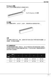
PCI Express 插槽 此PCI Express PCI The PCI Express x16 插槽 MS-7529 PCI 插槽 此PCI SCSI卡,USB PCI BIOS配置。 PCI IRQ,IRQ PCI的IRQ PCI PCI 1 PCI 2 1 INT A# INT B# 2 INT B# INT C# 3 INT C# INT D# 4 INT D# INT A# 111
PCI Express 插槽 此PCI Express PCI The PCI Express x16 插槽 MS-7529 PCI 插槽 此PCI SCSI卡,USB PCI BIOS配置。 PCI IRQ,IRQ PCI的IRQ PCI PCI 1 PCI 2 1 INT A# INT B# 2 INT B# INT C# 3 INT C# INT D# 4 INT D# INT A# 111
User Guide
Page 113
MS-7529 Cell Menu User Settings BIOS CMOS中。 M-Flash BIOS FAT/FAT32 Load Fail-Safe Defaults BIOS Load Optimized Defaults BIOS值。 Save & Exit Setup CMOS Setup程序。 Exit Without Saving CMOS Setup程序。 113
MS-7529 Cell Menu User Settings BIOS CMOS中。 M-Flash BIOS FAT/FAT32 Load Fail-Safe Defaults BIOS Load Optimized Defaults BIOS值。 Save & Exit Setup CMOS Setup程序。 Exit Without Saving CMOS Setup程序。 113
User Guide
Page 115
MS-7529 DIMM1~2 Memory SPD Information Enter Advance DRAM Configuration > DRAM CAS# Latency CAS DRAM 2T 2.5T By SPD DRAM CAS#由BIOS在DRAM模组基于SPD(Serial Presence Detect) EEPROM FSB/DRAM Ratio(FSB/DRAM FSB Adjusted DRAM Frequency (MHz MHZ ...
MS-7529 DIMM1~2 Memory SPD Information Enter Advance DRAM Configuration > DRAM CAS# Latency CAS DRAM 2T 2.5T By SPD DRAM CAS#由BIOS在DRAM模组基于SPD(Serial Presence Detect) EEPROM FSB/DRAM Ratio(FSB/DRAM FSB Adjusted DRAM Frequency (MHz MHZ ...
User Guide
Page 131
MS-7529 Cell Menu User Settings BIOS CMOS 或由 BIOS CMOS 載入。 M-Flash FAT/ FAT32 BIOS FAT/ FAT32 Load Fail-Safe Defaults BIOS Load Optimized Defaults BIOS Save & Exit Setup CMOS Exit Without Saving 131
MS-7529 Cell Menu User Settings BIOS CMOS 或由 BIOS CMOS 載入。 M-Flash FAT/ FAT32 BIOS FAT/ FAT32 Load Fail-Safe Defaults BIOS Load Optimized Defaults BIOS Save & Exit Setup CMOS Exit Without Saving 131
User Guide
Page 133
MS-7529 DIMM1~2 Memory SPD Information(DIMM1~2 記憶體 SPD Enter Advance DRAM Configuration > DRAM CAS# Latency (進階 DRAM 設定 > DRAM CAS CAS SDRAM 2T 2.5T By SPD BIOS 依 DRAM SPD EEPROM DRAM FSB/ DRAM Ratio (FSB FSB Adjusted DRAM Frequency (MHz Adjust PCI-E Frequency (MHz) (調整 PCI-E PCI-E 頻率。 Auto Disable DRAM/PCI Frequency PCI Enabled EMI)。 Spread Spectrum EMI EMI Disabled EMI Enabled EMI Disabled EMI 133
MS-7529 DIMM1~2 Memory SPD Information(DIMM1~2 記憶體 SPD Enter Advance DRAM Configuration > DRAM CAS# Latency (進階 DRAM 設定 > DRAM CAS CAS SDRAM 2T 2.5T By SPD BIOS 依 DRAM SPD EEPROM DRAM FSB/ DRAM Ratio (FSB FSB Adjusted DRAM Frequency (MHz Adjust PCI-E Frequency (MHz) (調整 PCI-E PCI-E 頻率。 Auto Disable DRAM/PCI Frequency PCI Enabled EMI)。 Spread Spectrum EMI EMI Disabled EMI Enabled EMI Disabled EMI 133
User Guide
Page 149
MS-7529 Cell Menu User Settings CMOS M-Flash (M USB BIOS Load Fail-Safe Defaults BIOS Load Optimized Defaults BIOS Save & Exit Setup CMOS Exit Without Saving CMOS 149
MS-7529 Cell Menu User Settings CMOS M-Flash (M USB BIOS Load Fail-Safe Defaults BIOS Load Optimized Defaults BIOS Save & Exit Setup CMOS Exit Without Saving CMOS 149


