User Manual
Page 2
...this document, but no solution can be obtained from the user's manual, please contact your place of its contents. W indows® 95/98/2000/NT/XP are registered trademarks of M ICRO-STAR INTERNATIONAL. Visit the MSI website for further guidance. Revision History Revision V1.0 Revision History ...guarantee is a registered trademark of American Megatrends Inc. We take every care in the United States and/or other information: http://global.msi.com.tw/index.php? NVIDIA, the NVIDIA logo, DualNet, and nForce are registered trademarks of NVIDIA Corporation in the preparation of this...
...this document, but no solution can be obtained from the user's manual, please contact your place of its contents. W indows® 95/98/2000/NT/XP are registered trademarks of M ICRO-STAR INTERNATIONAL. Visit the MSI website for further guidance. Revision History Revision V1.0 Revision History ...guarantee is a registered trademark of American Megatrends Inc. We take every care in the United States and/or other information: http://global.msi.com.tw/index.php? NVIDIA, the NVIDIA logo, DualNet, and nForce are registered trademarks of NVIDIA Corporation in the preparation of this...
User Manual
Page 3
... EQUIPMENT INANENVIRONMENT UNCONDITIONED, STORAGE TEMPERATURE ABOVE 600 C (1400F), IT MAYDAMAGE THE EQUIPMENT. ment from humidity. 4. fore connecting the equipment to User's Manual. † The equipment has dropped and damaged. † The equipment has obvious sign of the power source and adjust properly 110/220V be ... † The equipment has not work according to the power inlet. 7. DO NOT COVER THE OPENINGS. 6. Lay this User's Manual for air convection hence protects the equip- Place the power cord such a way that could damage or cause electrical s h oc k . 11.
... EQUIPMENT INANENVIRONMENT UNCONDITIONED, STORAGE TEMPERATURE ABOVE 600 C (1400F), IT MAYDAMAGE THE EQUIPMENT. ment from humidity. 4. fore connecting the equipment to User's Manual. † The equipment has dropped and damaged. † The equipment has obvious sign of the power source and adjust properly 110/220V be ... † The equipment has not work according to the power inlet. 7. DO NOT COVER THE OPENINGS. 6. Lay this User's Manual for air convection hence protects the equip- Place the power cord such a way that could damage or cause electrical s h oc k . 11.
User Manual
Page 15
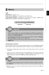
... memory module is properly inserted in Orange color. 64x2=128 pin 56x2=112 pin Important - Insert the m em ory module vertically into the DIMM1 first. Manually check if the memory m odule has been locked in GREEN color. Dual channels definition : DIMM slot(s) on Channel B are marked in place by the DIMM...
... memory module is properly inserted in Orange color. 64x2=128 pin 56x2=112 pin Important - Insert the m em ory module vertically into the DIMM1 first. Manually check if the memory m odule has been locked in GREEN color. Dual channels definition : DIMM slot(s) on Channel B are marked in place by the DIMM...

User Manual
Page 22
...refer to the TPM security platform manual for more details and usages. 12 LCLK 3Vdual / 3V_STB LRST# VCC3 LAD0 SIRQ LAD1 VCC5 LAD2 Key(no dam age will be caused. ATX 24-Pin Power Connector This connector ... Then push down the power supply firmly into the c on the mainbnoard have to connect to the ATX power supply and have to work together to ensure stable operation of the power supply is used to ...the CPU. 42 12V GND 12V GND 31 TPM module Connector This connector connects to use the 20-pin ATX power supply, please plug your power supply along with pin 1 & pin 13. 12 24 +3.3V GND...
...refer to the TPM security platform manual for more details and usages. 12 LCLK 3Vdual / 3V_STB LRST# VCC3 LAD0 SIRQ LAD1 VCC5 LAD2 Key(no dam age will be caused. ATX 24-Pin Power Connector This connector ... Then push down the power supply firmly into the c on the mainbnoard have to connect to the ATX power supply and have to work together to ensure stable operation of the power supply is used to ...the CPU. 42 12V GND 12V GND 31 TPM module Connector This connector connects to use the 20-pin ATX power supply, please plug your power supply along with pin 1 & pin 13. 12 24 +3.3V GND...
User Manual
Page 29
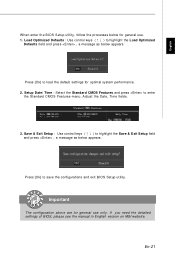
... appears: Press [Ok] to save the configurations and exit BIOS Setup utility. If you need the detailed settings of BIOS, please see the manual in English version on MSI website. En-21 English W hen enter the BIOS Setup utility, follow the processes below for general use only. Important The configuration above are...
... appears: Press [Ok] to save the configurations and exit BIOS Setup utility. If you need the detailed settings of BIOS, please see the manual in English version on MSI website. En-21 English W hen enter the BIOS Setup utility, follow the processes below for general use only. Important The configuration above are...


