User Manual
Page 2
...Support If a problem arises with your place of purchase or local distributor. Copyright Notice The material in this document, but no solution can be obtained from the user's manual, please contact your system and no guarantee is a registered trademark of AMD Corporation. Our products are registered trademarks of International... help resources for FAQ, technical guide, BIOS updates, driver updates, and other countries. PS/2 and OS®/2 are registered trademarks or trademarks of M ICRO-STAR INTERNATIONAL. Award® is given as to make changes without notice. We take every ...
...Support If a problem arises with your place of purchase or local distributor. Copyright Notice The material in this document, but no solution can be obtained from the user's manual, please contact your system and no guarantee is a registered trademark of AMD Corporation. Our products are registered trademarks of International... help resources for FAQ, technical guide, BIOS updates, driver updates, and other countries. PS/2 and OS®/2 are registered trademarks or trademarks of M ICRO-STAR INTERNATIONAL. Award® is given as to make changes without notice. We take every ...
User Manual
Page 3
... properly 110/220V be noted. 10. Lay this User's Manual for air convection hence protects the equip- The openings on card or module. 9. Make sure the voltage of expl os i on a reliable flat surface before inserting any of the following situations arises, get it work according to the power inlet. 7. Do not place anything over the...
... properly 110/220V be noted. 10. Lay this User's Manual for air convection hence protects the equip- The openings on card or module. 9. Make sure the voltage of expl os i on a reliable flat surface before inserting any of the following situations arises, get it work according to the power inlet. 7. Do not place anything over the...
User Manual
Page 8
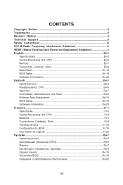
... Tradema rks ...ii Revision History ...ii Technical Support ...ii Safety Instructions iii FCC-B Radio Frequency Interference Statement iv WEEE (Waste Electrical and Electronic Equipment) Statement v English ...En-1 Specifications ...En-2 Central Processing Unit: CPU En-6 Memory ...En-7 Connectors, Jumpers, Slots En-9 Back Panel ...En-16 BIOS Setup ...En-18 Software Information En-22 Deutsch ...De-1 Spezifikationen De-2 Hauptprozessor: CPU De-6 Speicher ...De-7 Anschlüsse...
... Tradema rks ...ii Revision History ...ii Technical Support ...ii Safety Instructions iii FCC-B Radio Frequency Interference Statement iv WEEE (Waste Electrical and Electronic Equipment) Statement v English ...En-1 Specifications ...En-2 Central Processing Unit: CPU En-6 Memory ...En-7 Connectors, Jumpers, Slots En-9 Back Panel ...En-16 BIOS Setup ...En-18 Software Information En-22 Deutsch ...De-1 Spezifikationen De-2 Hauptprozessor: CPU De-6 Speicher ...De-7 Anschlüsse...
User Manual
Page 10
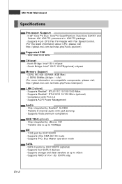
... up to 400Mbps IDE - 1 IDE port by Realtek® ALC888 - Supports four SATA II devices - Chip integrated by ICH7/ICH7R (optional) - Supports PIO, Bus Master operation mode SATA - SATA II ports by JMicron 381 - p hp ?f un c = c p uf or m ) Supported FSB - 800/1066/1333 MHz Chipset - Supports Realtek® RTL8111C 10/100/1000 Mb/s - South Bridge: Intel® ICH7/ ICH7R(optional) chipset Memory Support - Supports 4 pin CPU Fan Pin-Header with PCI 2.2 - Chip integrated by ICH7/ICH7R - Supports storage and data transfers...
... up to 400Mbps IDE - 1 IDE port by Realtek® ALC888 - Supports four SATA II devices - Chip integrated by ICH7/ICH7R (optional) - Supports PIO, Bus Master operation mode SATA - SATA II ports by JMicron 381 - p hp ?f un c = c p uf or m ) Supported FSB - 800/1066/1333 MHz Chipset - Supports Realtek® RTL8111C 10/100/1000 Mb/s - South Bridge: Intel® ICH7/ ICH7R(optional) chipset Memory Support - Supports 4 pin CPU Fan Pin-Header with PCI 2.2 - Chip integrated by ICH7/ICH7R - Supports storage and data transfers...
User Manual
Page 11
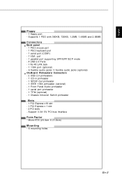
... Back panel - 1 PS/2 m ouse port - 1 PS/2 keyboard port - 1 serial port (COM1) - 1 VGA port - 1 parallel port supporting SPP/EPP/ECP mode - 4 USB 2.0 Ports - 1 RJ-45 LAN Jack - 1 1394 port (optional) - 6 flexible audio jacks/ 3 flexible audio jacks (optional) On-Board Pinheaders/ Connectors - 2 USB 2.0 pinheaders - 1 CD-in pinheader - 1 SPDIF-Out pinheader - 1 IEEE 1394 pinheader (optional) - 1 Front Panel Audio pinheader - 1 serial port pinheader - 1 TPM (optional) - 1 Chassis Intrusion Switch pinheader Slots - 1 PCI Express x16 slot - 1 PCI Express x 1 slot - 2 PCI slots - Micro-ATX (24...
... Back panel - 1 PS/2 m ouse port - 1 PS/2 keyboard port - 1 serial port (COM1) - 1 VGA port - 1 parallel port supporting SPP/EPP/ECP mode - 4 USB 2.0 Ports - 1 RJ-45 LAN Jack - 1 1394 port (optional) - 6 flexible audio jacks/ 3 flexible audio jacks (optional) On-Board Pinheaders/ Connectors - 2 USB 2.0 pinheaders - 1 CD-in pinheader - 1 SPDIF-Out pinheader - 1 IEEE 1394 pinheader (optional) - 1 Front Panel Audio pinheader - 1 serial port pinheader - 1 TPM (optional) - 1 Chassis Intrusion Switch pinheader Slots - 1 PCI Express x16 slot - 1 PCI Express x 1 slot - 2 PCI slots - Micro-ATX (24...
User Manual
Page 13
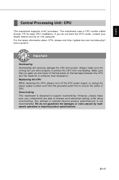
...) between the CPU and the heatsink to ensure the safety of CPU. We do not have the CPU cooler, consult your components are able to tolerate such abnormal setting, while doing overclocking. Any attempt to support overclocking. En-5 English Central Processing Unit: CPU The m ainboard supports Intel® processor. Replaceing the CPU While replacing the CPU, always turn off the ATX power supply or unplug the power supply's power cord from overheating...
...) between the CPU and the heatsink to ensure the safety of CPU. We do not have the CPU cooler, consult your components are able to tolerate such abnormal setting, while doing overclocking. Any attempt to support overclocking. En-5 English Central Processing Unit: CPU The m ainboard supports Intel® processor. Replaceing the CPU While replacing the CPU, always turn off the ATX power supply or unplug the power supply's power cord from overheating...
User Manual
Page 14
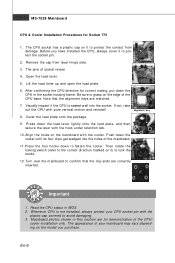
... keys are m atched. 7. Push down the cooler until its four clips get wedged into the socket. Important 1. The pins of your CPU socket pin with pure vertical motion and reinstall. Cover the load plate onto the package. 9. MS-7528 Mainboard CPU & Cooler Installation Procedures for demonstration of the CPU base. The CPU socket has a plastic cap on the edge of the CPU/ cooler installation only. Remove...
... keys are m atched. 7. Push down the cooler until its four clips get wedged into the socket. Important 1. The pins of your CPU socket pin with pure vertical motion and reinstall. Cover the load plate onto the package. 9. MS-7528 Mainboard CPU & Cooler Installation Procedures for demonstration of the CPU base. The CPU socket has a plastic cap on the edge of the CPU/ cooler installation only. Remove...
User Manual
Page 17
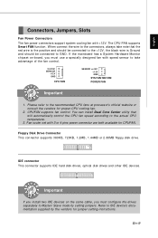
... setting instructions. Floppy Disk Drive Connector This connector supports 360KB, 720KB, 1.2MB, 1.44MB or 2.88MB floppy disk drive. The CPU FAN supports Smart FAN function. Fan cooler set with 3 or 4 pins power connector are both available for proper CPU cooling fan. 2. En-9 English Connectors, Jumpers, Slots Fan Power Connectors The fan power connectors support system cooling fan with speed sensor to IDE device's documentation supplied by setting jumpers. Please refer to the actual CPU temperature. 3. Important If you install two IDE devices on -board, you must use...
... setting instructions. Floppy Disk Drive Connector This connector supports 360KB, 720KB, 1.2MB, 1.44MB or 2.88MB floppy disk drive. The CPU FAN supports Smart FAN function. Fan cooler set with 3 or 4 pins power connector are both available for proper CPU cooling fan. 2. En-9 English Connectors, Jumpers, Slots Fan Power Connectors The fan power connectors support system cooling fan with speed sensor to IDE device's documentation supplied by setting jumpers. Please refer to the actual CPU temperature. 3. Important If you install two IDE devices on -board, you must use...

User Manual
Page 18
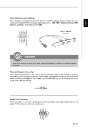
... a high-speed Serial ATA interface port. MS-7528 Mainboard Serial ATA Connector This connector is compliant with Intel® Front Panel I/O Connectivity Design Guide. Each connector can connect to connect the IEEE1394 device via an optional IEEE1394 brac ket . Ground TPA- Important Please do not fold the Serial ATA cable into 90-degree angle. Power Switch Power LED 10 9 21 JFP1 Reset Switch HDD LED 87 Speaker 2 1 JFP2 Power LED IEEE1394 Connector (Green) This connector allows you to one Serial ATA device. Front Panel Connectors...
... a high-speed Serial ATA interface port. MS-7528 Mainboard Serial ATA Connector This connector is compliant with Intel® Front Panel I/O Connectivity Design Guide. Each connector can connect to connect the IEEE1394 device via an optional IEEE1394 brac ket . Ground TPA- Important Please do not fold the Serial ATA cable into 90-degree angle. Power Switch Power LED 10 9 21 JFP1 Reset Switch HDD LED 87 Speaker 2 1 JFP2 Power LED IEEE1394 Connector (Green) This connector allows you to one Serial ATA device. Front Panel Connectors...
User Manual
Page 19
...® I/O Connectivity Design Guide, is a 16550A high speed com m unication port that the pins of VCC and GND must enter the BIOS utility and clear the record. 1 CINTRU GND Serial Port Connector This connector is ideal for connecting high-speed USB interface peripherals such as USB HDD, digital cameras, MP3 players, printers, modems and the like. You can attach a serial device. The system will be connected correctly to the chassis intrusion switch cable. To clear the warning...
...® I/O Connectivity Design Guide, is a 16550A high speed com m unication port that the pins of VCC and GND must enter the BIOS utility and clear the record. 1 CINTRU GND Serial Port Connector This connector is ideal for connecting high-speed USB interface peripherals such as USB HDD, digital cameras, MP3 players, printers, modems and the like. You can attach a serial device. The system will be connected correctly to the chassis intrusion switch cable. To clear the warning...

User Manual
Page 20
...® Front Panel I/O Connectivity Design Guide. L GND R S/PDIF-Out Connector or S/PDIF-In Connector This connector is used to connect the front panel audio and is provided for digital audio transm ission. Ground Presence# MIC_JD NC(No pin) LINE out_JD 2 10 1 9 MIC _L MIC _R LINE out_R Front_JD LINE out_L En-12 GND SPDIF_out VCC SPDIF_Out SPDIF Bracket (Optional) Front Panel Audio Connector (Azalia Spec) This connector allows you...
...® Front Panel I/O Connectivity Design Guide. L GND R S/PDIF-Out Connector or S/PDIF-In Connector This connector is used to connect the front panel audio and is provided for digital audio transm ission. Ground Presence# MIC_JD NC(No pin) LINE out_JD 2 10 1 9 MIC _L MIC _R LINE out_R Front_JD LINE out_L En-12 GND SPDIF_out VCC SPDIF_Out SPDIF Bracket (Optional) Front Panel Audio Connector (Azalia Spec) This connector allows you...

User Manual
Page 21
English Clear CMOS Jumper There is a CMOS RAM onboard that has a power supply from an external battery to 12 pin position. Then return to keep the data of system configuration. If you want to clear the system configuration, set the jumper to clear data. 1 1 1 Keep Data (default) Clear Data Important You can automatically boot OS every time it will damage the mainboard. it is turned on ; En-13 Avoid clearing the CMOS while the system is off. W ith the CMOS RAM, the system can clear CMOS by shorting 2-3 pin while the system is on .
English Clear CMOS Jumper There is a CMOS RAM onboard that has a power supply from an external battery to 12 pin position. Then return to keep the data of system configuration. If you want to clear the system configuration, set the jumper to clear data. 1 1 1 Keep Data (default) Clear Data Important You can automatically boot OS every time it will damage the mainboard. it is turned on ; En-13 Avoid clearing the CMOS while the system is off. W ith the CMOS RAM, the system can clear CMOS by shorting 2-3 pin while the system is on .

User Manual
Page 22
... LAD2 Key(no dam age will be caused. Please refer to connect an ATX 24-pin power supply. Then push down the power supply firmly into the c on the mainbnoard have to connect to the ATX power supply and have to work together to ensure stable operation of the power supply is used to provide power to the CPU. 42 12V GND 12V GND 31 TPM module Connector This connector connects...
... LAD2 Key(no dam age will be caused. Please refer to connect an ATX 24-pin power supply. Then push down the power supply firmly into the c on the mainbnoard have to connect to the ATX power supply and have to work together to ensure stable operation of the power supply is used to provide power to the CPU. 42 12V GND 12V GND 31 TPM module Connector This connector connects...
User Manual
Page 23
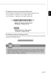
... adding or removing expansion cards, make sure that comply with PCI specifications. Mazarine PCI Express x16 Slots support PCI Express x 16 speed (PCI_E1) White PCI Express x 1 Slots support PCI Express x 1 speed (PCI_E2) PCI (Peripheral Component Interconnect) Slot The PCI slot supports LAN card, SCSI card, USB card, and other add-on cards that you unplug the power supply first. The PCI Express x 1 supports up to 4.0 GB/s transfer rate. Meanwhile, read the documentation for the expansion card, such as jumpers, switches or BIOS configuration. The PCI Express x 16 supports up to...
... adding or removing expansion cards, make sure that comply with PCI specifications. Mazarine PCI Express x16 Slots support PCI Express x 16 speed (PCI_E1) White PCI Express x 1 Slots support PCI Express x 1 speed (PCI_E2) PCI (Peripheral Component Interconnect) Slot The PCI slot supports LAN card, SCSI card, USB card, and other add-on cards that you unplug the power supply first. The PCI Express x 1 supports up to 4.0 GB/s transfer rate. Meanwhile, read the documentation for the expansion card, such as jumpers, switches or BIOS configuration. The PCI Express x 16 supports up to...

User Manual
Page 24
.../2 Keyboard connector (Purple/ 6-pin female) 1394 Port The IEEE1394 port on the back panel provides connection to it. The computer iscommunicating with anothercomputeron the LAN. 10 Mbit/sec data rate is selected. 100 Mbit/sec data rate is selected. 1000 Mbit/sec data rate is for a PS/2® mouse/keyboard. You can connect a network cable to IEEE1394 devices. USB Port The USB (Universal Serial Bus) port is selected. LED Color...
.../2 Keyboard connector (Purple/ 6-pin female) 1394 Port The IEEE1394 port on the back panel provides connection to it. The computer iscommunicating with anothercomputeron the LAN. 10 Mbit/sec data rate is selected. 100 Mbit/sec data rate is selected. 1000 Mbit/sec data rate is for a PS/2® mouse/keyboard. You can connect a network cable to IEEE1394 devices. USB Port The USB (Universal Serial Bus) port is selected. LED Color...
User Manual
Page 26
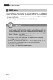
... released. Important 1.The items under continuous update for better system performance. MS-7528 Mainboard BIOS Setup This chapter provides basic information on the BIOS Setup program and allows you to run the Setup program when: * An error message appears on the screen during the system booting up , the 1st line appearing after the memory count is usually in this chapter are...
... released. Important 1.The items under continuous update for better system performance. MS-7528 Mainboard BIOS Setup This chapter provides basic information on the BIOS Setup program and allows you to run the Setup program when: * An error message appears on the screen during the system booting up , the 1st line appearing after the memory count is usually in this chapter are...

User Manual
Page 27
... will start POST (Power On Self Test) process. Then you find a right pointer symbol (as shown in the right view) appears to enter Setup, restart the system by turning it OFF and On or pressing the RESET button. You can m ake changes to. If you still wish to the left of the screen. The Help screen lists the appropriate keys to use the control keys to enter...
... will start POST (Power On Self Test) process. Then you find a right pointer symbol (as shown in the right view) appears to enter Setup, restart the system by turning it OFF and On or pressing the RESET button. You can m ake changes to. If you still wish to the left of the screen. The Help screen lists the appropriate keys to use the control keys to enter...
User Manual
Page 28
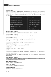
...-7528 Mainboard The Main Menu Once you to select from ten setup functions and two exit choices. The Main Menu allows you enter AMI® or AW ARD® BIOS CMOS Setup Utility, the Main Menu will appear on the screen. Power Management Features Use this menu to setup the item s of the m ai nboard. Load Fail-Safe Defaults Use this menu to specify your system supports PnP/PCI. PNP/PCI Configurations This entry appears if your settings...
...-7528 Mainboard The Main Menu Once you to select from ten setup functions and two exit choices. The Main Menu allows you enter AMI® or AW ARD® BIOS CMOS Setup Utility, the Main Menu will appear on the screen. Power Management Features Use this menu to setup the item s of the m ai nboard. Load Fail-Safe Defaults Use this menu to specify your system supports PnP/PCI. PNP/PCI Configurations This entry appears if your settings...
User Manual
Page 29
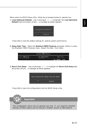
... version on MSI website. Setup Date/ Time : Select the Standard CMOS Features and press to save the configurations and exit BIOS Setup utility. Important The configuration above are for general use . 1. Save & Exit Setup : Use control keys (↑↓ ) to highlight the Save & Exit Setup field and press , a message as below appears: Press [Ok] to load the default settings for optimal system performance. 2. En-21 English W hen enter the BIOS Setup utility...
... version on MSI website. Setup Date/ Time : Select the Standard CMOS Features and press to save the configurations and exit BIOS Setup utility. Important The configuration above are for general use . 1. Save & Exit Setup : Use control keys (↑↓ ) to highlight the Save & Exit Setup field and press , a message as below appears: Press [Ok] to load the default settings for optimal system performance. 2. En-21 English W hen enter the BIOS Setup utility...
User Manual
Page 30
... menu- The installation will auto-run, sim ply click the driver or utiltiy and follow the pop-up screen to activate the device. The Driver/Utility CD contains the: Driver menu - Utility m enu - The Utility menu shows the software applications that is included in the mainboard package, and place it into the CD-ROM driver. En-22 Important Please visit the MSI website to get the latest drivers and BIOS...
... menu- The installation will auto-run, sim ply click the driver or utiltiy and follow the pop-up screen to activate the device. The Driver/Utility CD contains the: Driver menu - Utility m enu - The Utility menu shows the software applications that is included in the mainboard package, and place it into the CD-ROM driver. En-22 Important Please visit the MSI website to get the latest drivers and BIOS...

