User Guide
Page 8
... 2. Hardware Setup 2-1 Quick Components Guide 2-2 CPU (Central Processing Unit 2-2 Introduction to LGA 775 CPU 2-3 CPU & Cooler Installation 2-5 Memory ...2-6 Introduction to DDRII SDRAM 2-7 Memory Module Population Rules 2-7 Installing DDRII Modules 2-8 Power Supply ...2-8 ATX 24-Pin Power Connector: ATX 2-9 ATX 12V Power Connector: JPW/ JPWR 2-9 IEEE 1394 Port (optional 2-10 Mouse/Keyboard Connector 2-11 Back Panel ...2-11...
... 2. Hardware Setup 2-1 Quick Components Guide 2-2 CPU (Central Processing Unit 2-2 Introduction to LGA 775 CPU 2-3 CPU & Cooler Installation 2-5 Memory ...2-6 Introduction to DDRII SDRAM 2-7 Memory Module Population Rules 2-7 Installing DDRII Modules 2-8 Power Supply ...2-8 ATX 24-Pin Power Connector: ATX 2-9 ATX 12V Power Connector: JPW/ JPWR 2-9 IEEE 1394 Port (optional 2-10 Mouse/Keyboard Connector 2-11 Back Panel ...2-11...

User Guide
Page 13
... sensing - Supports Intel® Dual Core Technology to 800 MHz and up to 3.0 Gb/s RAID - Supports Intel® ViivTM Technology Memory Support** - Intel® Core 2 Duo, Pemtium 4 Extreme Edition, Pentium 4, Pentium D, and Celeron D processors in the LGA775 package. - North Bridge: Intel®...; 975X chipset - Transfer rate is up Supported FSB - 1066/ 800/ 533 MHz Chipset - Supports Ultra DMA 66/100/133 m ode - Supports five SATA II...
... sensing - Supports Intel® Dual Core Technology to 800 MHz and up to 3.0 Gb/s RAID - Supports Intel® ViivTM Technology Memory Support** - Intel® Core 2 Duo, Pemtium 4 Extreme Edition, Pentium 4, Pentium D, and Celeron D processors in the LGA775 package. - North Bridge: Intel®...; 975X chipset - Transfer rate is up Supported FSB - 1066/ 800/ 533 MHz Chipset - Supports Ultra DMA 66/100/133 m ode - Supports five SATA II...
User Guide
Page 14
ATX (30.4cm X 24.5 cm) Mounting - 9 mounting holes * For the latest information about CPU, please visit http://www.msi.com.tw/ program/products/mainboard/mbd/pro_mbd_cpu_support.php ** For the updated supporting memory modules, please visit http://www.msi. wireless LAN and bluetooth combo card.) - com.tw/program/products/mainboard/mbd/pro_mbd_trp_list.php 1-3 Supports 1 FDD ... pinheaders - 1 IEEE 1394 pinheader Slots - 2 PCI Express x16 slots (support into two x 8ports) - 2 PCI Express x1 slots - 2 PCI slots. - 1 orange slot which supports 2 masters for MSI special PCI function card (ex.
ATX (30.4cm X 24.5 cm) Mounting - 9 mounting holes * For the latest information about CPU, please visit http://www.msi.com.tw/ program/products/mainboard/mbd/pro_mbd_cpu_support.php ** For the updated supporting memory modules, please visit http://www.msi. wireless LAN and bluetooth combo card.) - com.tw/program/products/mainboard/mbd/pro_mbd_trp_list.php 1-3 Supports 1 FDD ... pinheaders - 1 IEEE 1394 pinheader Slots - 2 PCI Express x16 slots (support into two x 8ports) - 2 PCI Express x1 slots - 2 PCI slots. - 1 orange slot which supports 2 masters for MSI special PCI function card (ex.

User Guide
Page 17
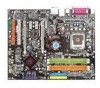
Chapter 2 Hardware Setup This chapter tells you how to setup the jumpers on connecting the peripheral devices, such as how to install the CPU, memory modules, and expansion cards, as well as the mouse, keyboard, etc. While doing the installation, be careful in holding the components and follow the installation procedures. Also, it provides the instructions on the mainboard.
Chapter 2 Hardware Setup This chapter tells you how to setup the jumpers on connecting the peripheral devices, such as how to install the CPU, memory modules, and expansion cards, as well as the mouse, keyboard, etc. While doing the installation, be careful in holding the components and follow the installation procedures. Also, it provides the instructions on the mainboard.
User Guide
Page 23
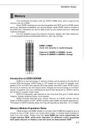
... DDR, while both channels (in different color) populated with DDR and the DDRII standard is not backwardly compatible and only motherboards specifically designed for DDRII memory will be less than DDR chips. DDRII modules have smaller and tighter spaced pins. Please note that give it better signal...is the top limit of DDRII modules varies, but will require some changes as dual-channel DDR. 2-7 For the updated supporting memory modules, please visit http://www.msi. DDRII uses a 1.8V supply for DDR, and requires 28% less power than 1.3" in the DDRII slot. or double-sided...
... DDR, while both channels (in different color) populated with DDR and the DDRII standard is not backwardly compatible and only motherboards specifically designed for DDRII memory will be less than DDR chips. DDRII modules have smaller and tighter spaced pins. Please note that give it better signal...is the top limit of DDRII modules varies, but will require some changes as dual-channel DDR. 2-7 For the updated supporting memory modules, please visit http://www.msi. DDRII uses a 1.8V supply for DDR, and requires 28% less power than 1.3" in the DDRII slot. or double-sided...

User Guide
Page 24
...in the right orientation. 2. The plastic clip at each DIMM is properly inserted in the previous page. - Please select the identical memory modules to insert the memory modules into the DIMM slot. Installing DDRII Modules 1. Volt Notch Important You can barely see the golden finger if the module is ...installed with an 1GB memory module. Due to the South Bridge resource deployment, the system density will only be detected up to 7+GB (not full 8GB) when each...
...in the right orientation. 2. The plastic clip at each DIMM is properly inserted in the previous page. - Please select the identical memory modules to insert the memory modules into the DIMM slot. Installing DDRII Modules 1. Volt Notch Important You can barely see the golden finger if the module is ...installed with an 1GB memory module. Due to the South Bridge resource deployment, the system density will only be detected up to 7+GB (not full 8GB) when each...
User Guide
Page 37
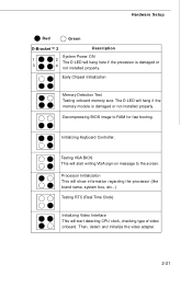
... will show information regarding the processor (like brand name, system bus, etc...) Testing RTC (Real Time Clock) Initializing Video Interface This will hang if the memory module is damaged or 3 4 not installed properly. Early Chipset Initialization...
... will show information regarding the processor (like brand name, system bus, etc...) Testing RTC (Real Time Clock) Initializing Video Interface This will hang if the memory module is damaged or 3 4 not installed properly. Early Chipset Initialization...
User Guide
Page 38
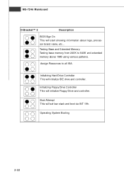
Initializing Floppy Drive Controller This will set low stack and boot via INT 19h. Assign Resources to 640K and extended memory above 1MB using various patterns. Boot Attempt This will initialize Floppy Drive and controller. MS-7246 Mainboard D-Bracket™ 2 Description BIOS Sign On This will initialize IDE drive and controller. Testing Base and Extended Memory Testing base memory from 240K to all ISA. Initializing Hard Drive Controller This will start showing information about logo, processor brand name, etc... Operating System Booting 2-22
Initializing Floppy Drive Controller This will set low stack and boot via INT 19h. Assign Resources to 640K and extended memory above 1MB using various patterns. Boot Attempt This will initialize Floppy Drive and controller. MS-7246 Mainboard D-Bracket™ 2 Description BIOS Sign On This will initialize IDE drive and controller. Testing Base and Extended Memory Testing base memory from 240K to all ISA. Initializing Hard Drive Controller This will start showing information about logo, processor brand name, etc... Operating System Booting 2-22
User Guide
Page 45
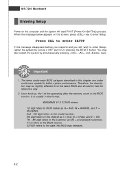
... respond and you still wish to enter Setup, restart the system by simultaneously pressing , , and keys. Upon boot-up, the 1st line appearing after the memory count is usually in this BIOS was released. 3-2 MS-7246 Mainboard Entering Setup Power on the screen, press key to enter Setup. W hen the message...
... respond and you still wish to enter Setup, restart the system by simultaneously pressing , , and keys. Upon boot-up, the 1st line appearing after the memory count is usually in this BIOS was released. 3-2 MS-7246 Mainboard Entering Setup Power on the screen, press key to enter Setup. W hen the message...
User Guide
Page 50
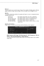
.../ CPU Type/ CPU ID/uCode ID / CPU Frequency/ CPU L2 Cache/ Total Physical M emory/ Usage M emory The items show the CPU type, BIOS version and memory status of floppy drive installed.
.../ CPU Type/ CPU ID/uCode ID / CPU Frequency/ CPU L2 Cache/ Total Physical M emory/ Usage M emory The items show the CPU type, BIOS version and memory status of floppy drive installed.
User Guide
Page 51
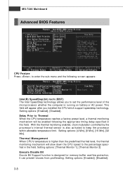
With the thermal monitoring enabled, clock modulation controlled by the processor's internal thermal sensor is designed for memory buffer overflow protection, it can prevent viruses from proliferating. Thermal Management W hen CPU's temperature is higher than the predefined thermal level, the thermal monitoring mechanism ...
With the thermal monitoring enabled, clock modulation controlled by the processor's internal thermal sensor is designed for memory buffer overflow protection, it can prevent viruses from proliferating. Thermal Management W hen CPU's temperature is higher than the predefined thermal level, the thermal monitoring mechanism ...
User Guide
Page 54
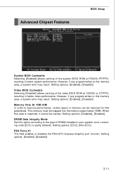
...to improve performance, certain space in your system: error-correcting code (ECC) or parity (default). Setting options: [Enabled], [Disabled]. This memory must be cached. Setting options: [Disabled], [Enabled]. PEG Force X1 The field enables or disables the PEG (PCI Express Graphic) port... BIOS Cacheable Selecting [Enabled] allows caching of the video BIOS ROM at F0000h-FFFFFh, resulting in better system performance. W hen this memory area, a system error may result. Setting optoins: [ECC], [Non-ECC]. Advanced Chipset Features BIOS Setup System BIOS Cacheable Selecting [Enabled...
...to improve performance, certain space in your system: error-correcting code (ECC) or parity (default). Setting options: [Enabled], [Disabled]. This memory must be cached. Setting options: [Disabled], [Enabled]. PEG Force X1 The field enables or disables the PEG (PCI Express Graphic) port... BIOS Cacheable Selecting [Enabled] allows caching of the video BIOS ROM at F0000h-FFFFFh, resulting in better system performance. W hen this memory area, a system error may result. Setting optoins: [ECC], [Non-ECC]. Advanced Chipset Features BIOS Setup System BIOS Cacheable Selecting [Enabled...

User Guide
Page 59
... State This item specifies the power saving modes for ACPI function. Video Off In Suspend This option enables the monitor to be used to main memory that remains powered while most other hardware compo nents turn off during the suspend mode. Setting options: [Enabled] and [Disabled]. If your operating system is... Management Setup Important S3-related functions described in this section are : [S1 (POS)] The S1 sleep mode is a low power state. The information stored in memory will be turned off to activate the ACPI (Advanced Configuration and Power Management Interface) Function.
... State This item specifies the power saving modes for ACPI function. Video Off In Suspend This option enables the monitor to be used to main memory that remains powered while most other hardware compo nents turn off during the suspend mode. Setting options: [Enabled] and [Disabled]. If your operating system is... Management Setup Important S3-related functions described in this section are : [S1 (POS)] The S1 sleep mode is a low power state. The information stored in memory will be turned off to activate the ACPI (Advanced Configuration and Power Management Interface) Function.
User Guide
Page 66
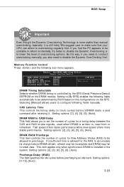
... to , read command after receiving it. Setting options: [2], [3], [4], [5], [6], [Auto]. Precharge Delay (tRAS) The field specifies the idle cycles before SDRAM starts a read from or refreshed. Memory Function Control Press and the following fields manually. Setting to [By SPD] enables the following fields automatically to lower the level of cycles for the...
... to , read command after receiving it. Setting options: [2], [3], [4], [5], [6], [Auto]. Precharge Delay (tRAS) The field specifies the idle cycles before SDRAM starts a read from or refreshed. Memory Function Control Press and the following fields manually. Setting to [By SPD] enables the following fields automatically to lower the level of cycles for the...

User Guide
Page 67
...]~ [150]. These settings offer users a tool to minimize the electromagnetic interference (EMI). Settings: [Enabled], [Disabled]. 3-24 MS-7246 Mainboard FSB & Memory Clock Ratio These settings control the ratio of your PCI Express card when overclocking, but the stability may cause a stability issue, so changing the... memory voltage for long-term purpose is adjustable in the individual fields, allowing you to select the CPU Front Side Bus clock frequency ...
...]~ [150]. These settings offer users a tool to minimize the electromagnetic interference (EMI). Settings: [Enabled], [Disabled]. 3-24 MS-7246 Mainboard FSB & Memory Clock Ratio These settings control the ratio of your PCI Express card when overclocking, but the stability may cause a stability issue, so changing the... memory voltage for long-term purpose is adjustable in the individual fields, allowing you to select the CPU Front Side Bus clock frequency ...
User Guide
Page 68
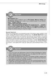
...if your setting is proper for optimal system stability and performance. BIOS Setup Important MSI Reminds You... The settings shown in different color in clock speed which may ... are overclocking because even a slight jitter can introduce a temporary boost in CPU Voltage, Memory Voltage and PCI Express Voltage help to lock up . 3-25 But if you are... of the pulses creates EMI (Electromagnetic Interference). Remember to flatter curves. Spread Spectrum W hen the motherboard's clock generator pulses, the extreme values (spikes) of the system; Red: Not recommended setting and...
...if your setting is proper for optimal system stability and performance. BIOS Setup Important MSI Reminds You... The settings shown in different color in clock speed which may ... are overclocking because even a slight jitter can introduce a temporary boost in CPU Voltage, Memory Voltage and PCI Express Voltage help to lock up . 3-25 But if you are... of the pulses creates EMI (Electromagnetic Interference). Remember to flatter curves. Spread Spectrum W hen the motherboard's clock generator pulses, the extreme values (spikes) of the system; Red: Not recommended setting and...

User Guide
Page 69
...the system is restored to reboot the system three times. Press the Power button to the defaults setting. W arning !!! Memory speed = FSB Frequency x Memory Ratio x Double Data Rate 3. At the fourth reboot, BIOS will not be under our product warranty. CPU Clock = .... The previous performance of more information. This motherboard supports overclocking greatly. Any operation that the previous overclocking is not recommended. Reboot 1. MS-7246 Mainboard CPU and Memory Clock Overclocking The Dynamic OverClocking / FSB & Memory Clock Ratio/ Adjust CPU Ratio/ CPU FSB ...
...the system is restored to reboot the system three times. Press the Power button to the defaults setting. W arning !!! Memory speed = FSB Frequency x Memory Ratio x Double Data Rate 3. At the fourth reboot, BIOS will not be under our product warranty. CPU Clock = .... The previous performance of more information. This motherboard supports overclocking greatly. Any operation that the previous overclocking is not recommended. Reboot 1. MS-7246 Mainboard CPU and Memory Clock Overclocking The Dynamic OverClocking / FSB & Memory Clock Ratio/ Adjust CPU Ratio/ CPU FSB ...
User Guide
Page 71
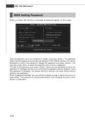
..., a message as below will appear on the screen: Type the password, up confirming the password will be disabled. This prevents an unauthorized person from CMOS memory. Retype the password and press . A message will be prompted to six characters in length, and press . W hen a password has been set password from changing any...
..., a message as below will appear on the screen: Type the password, up confirming the password will be disabled. This prevents an unauthorized person from CMOS memory. Retype the password and press . A message will be prompted to six characters in length, and press . W hen a password has been set password from changing any...

User Guide
Page 72
... Appendix A Introduction to DigiCell DigiCell, the most useful and powerful utility that MSI has spent much research and efforts to develop, helps users to overclock the CPU/memory. Moreover, with this unique utility, you will be able to activate the MSI well-known features, Live Update and Core Center, which makes it easier...
... Appendix A Introduction to DigiCell DigiCell, the most useful and powerful utility that MSI has spent much research and efforts to develop, helps users to overclock the CPU/memory. Moreover, with this unique utility, you will be able to activate the MSI well-known features, Live Update and Core Center, which makes it easier...
User Guide
Page 147
... Celeron, AMD Athlon XP/ Sempron or compatible CPU with PCI Express slot. 2. 256MB system memory. 3. Dual Core Center Appendix E Dual Core Center Dual CoreCenter, the most useful and powerful utility that MSI has spent much research and efforts to develop, helps users to monitor or configure the hardware status... of MSI Mainboard & MSI Graphics card in windows, such as CPU/GPU clock, voltage, fan speed and...
... Celeron, AMD Athlon XP/ Sempron or compatible CPU with PCI Express slot. 2. 256MB system memory. 3. Dual Core Center Appendix E Dual Core Center Dual CoreCenter, the most useful and powerful utility that MSI has spent much research and efforts to develop, helps users to monitor or configure the hardware status... of MSI Mainboard & MSI Graphics card in windows, such as CPU/GPU clock, voltage, fan speed and...


