
User Guide
Page 2
... information: http://www.msi.com.tw/program/service/faq/ faq/esc_faq_list.php Contact our technical staff at: http://support.msi.com.tw ii PS/2 and OS®/2 are registered trademarks of AMD Corporation. Netware® is a registered trademark of International Business Machines Corporation. Alternatively, please try the following help resources for FAQ, technical guide, BIOS updates, driver updates, and other countries...
... information: http://www.msi.com.tw/program/service/faq/ faq/esc_faq_list.php Contact our technical staff at: http://support.msi.com.tw ii PS/2 and OS®/2 are registered trademarks of AMD Corporation. Netware® is a registered trademark of International Business Machines Corporation. Alternatively, please try the following help resources for FAQ, technical guide, BIOS updates, driver updates, and other countries...
User Guide
Page 8
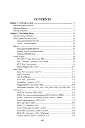
...Specifications 1-2 Mainboard Layout 1-4 Packing Checklist 1-4 Chapter 2. Hardware Setup 2-1 Quick Components Guide 2-2 CPU (Central Processing Unit 2-2 Introduction to LGA 775 CPU 2-3 CPU & Cooler Installation 2-5 Memory ...2-6 Introduction to DDRII SDRAM 2-7 Memory Module Population Rules 2-7 Installing DDRII Modules 2-8 Power Supply ...2-8 ATX 24-Pin Power Connector: ATX 2-9 ATX 12V Power Connector: JPW/ JPWR 2-9 IEEE 1394 Port (optional 2-10 Mouse/Keyboard Connector 2-11 Back Panel ...2-11 Serial Port Connector: COM Port 2-11 USB Connectors 2-11 LAN (RJ-45) Jack 2-13 Audio...
...Specifications 1-2 Mainboard Layout 1-4 Packing Checklist 1-4 Chapter 2. Hardware Setup 2-1 Quick Components Guide 2-2 CPU (Central Processing Unit 2-2 Introduction to LGA 775 CPU 2-3 CPU & Cooler Installation 2-5 Memory ...2-6 Introduction to DDRII SDRAM 2-7 Memory Module Population Rules 2-7 Installing DDRII Modules 2-8 Power Supply ...2-8 ATX 24-Pin Power Connector: ATX 2-9 ATX 12V Power Connector: JPW/ JPWR 2-9 IEEE 1394 Port (optional 2-10 Mouse/Keyboard Connector 2-11 Back Panel ...2-11 Serial Port Connector: COM Port 2-11 USB Connectors 2-11 LAN (RJ-45) Jack 2-13 Audio...
User Guide
Page 10
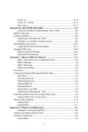
... On A-15 Power Off / Restart A-16 Auto Login A-17 Appendix B. Intel ICH7HD SATA RAID B-1 Using the Intel Matrix Stroage Manager Option ROM B-2 BIOS Configuration B-2 Installing Software B-8 Install Driver in W indows XP / 2000 B-9 Installation of Independent Disks C-2 RAID 0 (Striping C-2 RAID 1 (Mirroring C-2 JBOD (Concatenate C-2 Introduction ...C-2 Creating and Deleting RAID sets with BIOS Utility C-3 Main Menu ...C-3 Hard Disk Driver List C-3 RAID Disk Driver List C-3 Creating RAID set C-4 Deleting RAID set C-7 Revert HDD to non-RAID C-8 Install Driver in W indows XP...
... On A-15 Power Off / Restart A-16 Auto Login A-17 Appendix B. Intel ICH7HD SATA RAID B-1 Using the Intel Matrix Stroage Manager Option ROM B-2 BIOS Configuration B-2 Installing Software B-8 Install Driver in W indows XP / 2000 B-9 Installation of Independent Disks C-2 RAID 0 (Striping C-2 RAID 1 (Mirroring C-2 JBOD (Concatenate C-2 Introduction ...C-2 Creating and Deleting RAID sets with BIOS Utility C-3 Main Menu ...C-3 Hard Disk Driver List C-3 RAID Disk Driver List C-3 Creating RAID set C-4 Deleting RAID set C-7 Revert HDD to non-RAID C-8 Install Driver in W indows XP...

User Guide
Page 13
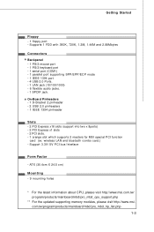
... device - Supports Intel® Dual Core Technology to 400Mbps Audio - South Bridge: Intel® ICH7DH chipset - SATA II ports by ICH7DH, JMB361 - Supports 3/4 pin CPU Fan Pin-Header with jack sensing - Flexible 8-channel audio with Fan Speed Control. - Transfer rate is up to 800 MHz and up to 3.0 Gb/s RAID - Com pliant with Azalia 1.0 Spec IDE - 2 IDE ports by JMicron SATARAID - SATA1~4 supports RAID 0/ 1/ 0+1 mode by Realtek® ALC882M - Supports Ultra DMA 66/100/133 m ode - Supports Intel® ViivTM Technology Memory Support** - Supports storage...
... device - Supports Intel® Dual Core Technology to 400Mbps Audio - South Bridge: Intel® ICH7DH chipset - SATA II ports by ICH7DH, JMB361 - Supports 3/4 pin CPU Fan Pin-Header with jack sensing - Flexible 8-channel audio with Fan Speed Control. - Transfer rate is up to 800 MHz and up to 3.0 Gb/s RAID - Com pliant with Azalia 1.0 Spec IDE - 2 IDE ports by JMicron SATARAID - SATA1~4 supports RAID 0/ 1/ 0+1 mode by Realtek® ALC882M - Supports Ultra DMA 66/100/133 m ode - Supports Intel® ViivTM Technology Memory Support** - Supports storage...
User Guide
Page 14
... port - 1 PS/2 keyboard port - 1 serial port (COM1) - 1 parallel port supporting SPP/EPP/ECP mode - 1 IEEE 1394 port - 4 USB 2.0 Ports. - 1 LAN jack (10/100/1000) - 6 flexible audio jacks. - 1 SPDIF jack. Support 3.3V/ 5V PCI bus Interface Form Factor - wireless LAN and bluetooth combo card.) - ATX (30.4cm X 24.5 cm) Mounting - 9 mounting holes * For the latest information about CPU, please visit http://www.msi.com.tw/ program/products/mainboard/mbd/pro_mbd_cpu_support.php ** For the updated supporting memory modules...
... port - 1 PS/2 keyboard port - 1 serial port (COM1) - 1 parallel port supporting SPP/EPP/ECP mode - 1 IEEE 1394 port - 4 USB 2.0 Ports. - 1 LAN jack (10/100/1000) - 6 flexible audio jacks. - 1 SPDIF jack. Support 3.3V/ 5V PCI bus Interface Form Factor - wireless LAN and bluetooth combo card.) - ATX (30.4cm X 24.5 cm) Mounting - 9 mounting holes * For the latest information about CPU, please visit http://www.msi.com.tw/ program/products/mainboard/mbd/pro_mbd_cpu_support.php ** For the updated supporting memory modules...
User Guide
Page 23
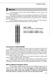
... support these chips. Memory Module Population Rules Install at the chip level that each DIM M can install either single- Each DIMM slot supports up your system and your mainboard might be damaged. For the updated supporting memory modules, please visit http://www.msi. DDRII uses a 1.8V supply for core and I/O voltage, compared to a maximum size of current DDR technology. Please note that give it better signal integrity, thereby enabling higher clock speeds...
... support these chips. Memory Module Population Rules Install at the chip level that each DIM M can install either single- Each DIMM slot supports up your system and your mainboard might be damaged. For the updated supporting memory modules, please visit http://www.msi. DDRII uses a 1.8V supply for core and I/O voltage, compared to a maximum size of current DDR technology. Please note that give it better signal integrity, thereby enabling higher clock speeds...
User Guide
Page 25
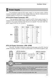
... Important 1. ATX 12V power connection should be caused. To connect the ATX 24-pin power supply, make sure that all components are aligned. Power supply of 450 watts (and above) is inserted in the proper orientation and the pins are installed properly to the CPU. Hardware Setup Power Supply The mainboard supports ATX power supply for system stability. 3. Before inserting the power supply connector, always make sure the plug of the mainboard. 2. ATX 24-Pin Power Connector: ATX This connector allows you...
... Important 1. ATX 12V power connection should be caused. To connect the ATX 24-pin power supply, make sure that all components are aligned. Power supply of 450 watts (and above) is inserted in the proper orientation and the pins are installed properly to the CPU. Hardware Setup Power Supply The mainboard supports ATX power supply for system stability. 3. Before inserting the power supply connector, always make sure the plug of the mainboard. 2. ATX 24-Pin Power Connector: ATX This connector allows you...
User Guide
Page 31
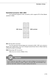
... (Secondary IDE Connector) IDE2 only can connect a Master and a Slave drive. IDE1 (blue) IDE2 (yellow) IDE1 (Primary IDE Connector) The first hard drive should always be connected to Slave mode by hard disk vendors for jumper setting instructions. 2-15 Refer to Slave mode by setting the jumper accordingly. Important If you install two hard disks on cable, you must configure second hard drive to the hard disk documentation supplied by setting its jumper. Hardware Setup Hard Disk Connector: IDE1/ IDE2 The mainboard supports 2 IDE connectors, which supports PIO & Bus Master...
... (Secondary IDE Connector) IDE2 only can connect a Master and a Slave drive. IDE1 (blue) IDE2 (yellow) IDE1 (Primary IDE Connector) The first hard drive should always be connected to Slave mode by hard disk vendors for jumper setting instructions. 2-15 Refer to Slave mode by setting the jumper accordingly. Important If you install two hard disks on cable, you must configure second hard drive to the hard disk documentation supplied by setting its jumper. Hardware Setup Hard Disk Connector: IDE1/ IDE2 The mainboard supports 2 IDE connectors, which supports PIO & Bus Master...
User Guide
Page 40
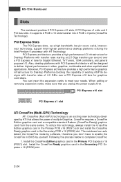
... 2-24 MS-7246 Mainboard Slots The mainboard provides 2 PCI Express x16 slots, 2 PCI Express x1 slots and 2 PCI bus slots. CrossFire requires a CrossFire Edition graphics card and a compatible standard Radeon (CrossFire Ready) graphics card from the same series. Install the CrossFire Edition graphics card in BIOS by ATI that allows the power of multiple Graphics. PCI Express Slots The PCI Express slots, as a high-bandwidth, low pin count, serial, interconnect technology, support Intel highest performance desktop platforms utilizing the Intel Pentium 4 processor with transfer rates of...
... 2-24 MS-7246 Mainboard Slots The mainboard provides 2 PCI Express x16 slots, 2 PCI Express x1 slots and 2 PCI bus slots. CrossFire requires a CrossFire Edition graphics card and a compatible standard Radeon (CrossFire Ready) graphics card from the same series. Install the CrossFire Edition graphics card in BIOS by ATI that allows the power of multiple Graphics. PCI Express Slots The PCI Express slots, as a high-bandwidth, low pin count, serial, interconnect technology, support Intel highest performance desktop platforms utilizing the Intel Pentium 4 processor with transfer rates of...
User Guide
Page 41
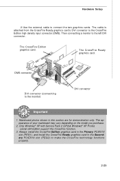
... x64 Edition support the CrossFire function. 3. DMS connector DVI connector (connectting to the CrossFire Edition high density input connector (DMS). The cable is attached from the CrossFire Ready graphics card's DVI connector to the monitor) DVI connector Important 1. Hardware Setup 2.Use the external cable to connect the two graphics cards. The appearance of your mainboard may vary depending on the model you purchase. 2. Mainboard photos shown in the Secondary PCIEX16 slot (PEG2...
... x64 Edition support the CrossFire function. 3. DMS connector DVI connector (connectting to the CrossFire Edition high density input connector (DMS). The cable is attached from the CrossFire Ready graphics card's DVI connector to the monitor) DVI connector Important 1. Hardware Setup 2.Use the external cable to connect the two graphics cards. The appearance of your mainboard may vary depending on the model you purchase. 2. Mainboard photos shown in the Secondary PCIEX16 slot (PEG2...
User Guide
Page 49
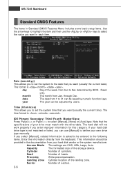
... documentation from the keyboard. Landing Z one Cylinder location of sectors. 3-6 day Day of the week, from Jan. year The year can use the or keys to select the value you want in each item. The time format is . The hard disk will not work properly if you to set the system time that the specifications of the storage device. Sector Number...
... documentation from the keyboard. Landing Z one Cylinder location of sectors. 3-6 day Day of the week, from Jan. year The year can use the or keys to select the value you want in each item. The time format is . The hard disk will not work properly if you to set the system time that the specifications of the storage device. Sector Number...

User Guide
Page 56
... the user chooses the onboard parallel port with the EPP function, the following options: [Disabled] [3BC/IRQ7] Line Printer port 0 [278/IRQ5] Line Printer port 2 [378/IRQ7] Line Printer port 1 Parallel Port Mode This field selects the operation mode for the first serial port. COM Port Select an address and corresponding interrupt for the onboard parallel port. Setting options: [Enabled], [Disabled]. Onboard Parallel Port There is EPP Spec. BIOS Setup Onboard BCM GB LAN This field controls the onboard...
... the user chooses the onboard parallel port with the EPP function, the following options: [Disabled] [3BC/IRQ7] Line Printer port 0 [278/IRQ5] Line Printer port 2 [378/IRQ7] Line Printer port 1 Parallel Port Mode This field selects the operation mode for the first serial port. COM Port Select an address and corresponding interrupt for the onboard parallel port. Setting options: [Enabled], [Disabled]. Onboard Parallel Port There is EPP Spec. BIOS Setup Onboard BCM GB LAN This field controls the onboard...
User Guide
Page 57
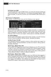
... Mainboard ECP Mode Use DMA The ECP mode has to enable BIOS support. At this option to [Enabled] to specify that the onboard IDE interface supports. Setting options: [Enabled], [Disabled]. OnChip Primary PCI IDE The integrated peripheral controller contains an IDE interface with the ECP feature. If your hard drive and your system software both support Ultra DMA/33, Ultra DMA/66 and Ultra DMA/100, select Auto to use the DMA channel, so choose the onboard parallel port...
... Mainboard ECP Mode Use DMA The ECP mode has to enable BIOS support. At this option to [Enabled] to specify that the onboard IDE interface supports. Setting options: [Enabled], [Disabled]. OnChip Primary PCI IDE The integrated peripheral controller contains an IDE interface with the ECP feature. If your hard drive and your system software both support Ultra DMA/33, Ultra DMA/66 and Ultra DMA/100, select Auto to use the DMA channel, so choose the onboard parallel port...
User Guide
Page 58
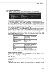
... the compatible SATA Spec version. Setting options: [Disabled], [Force GEN I], [Force GEN II]. Select [AHCI] to allow you to select the SATA and the ATA/IDE configuration. SATA Only PATA Pri, SATA Sec SATA Pri, PATA Sec PATA Only On-Chip Serial ATA (Combined) [SATA 1/3/2/4] [IDE1, SATA2/4] [SATA1/3, IDE1] [IDE1] IDE AHCI RAID On-Chip Serial ATA (Enhanced) [IDE1, SATA 1/2/3/4] [IDE1, SATA 1/2/3/4] [IDE1, SATA 1/2/3/4], [SATA support RAID 0/ 1/ 5/ 10] SATA PORT Speed Settings This item let you want to have Advanced Host Controller Interface (AHCI...
... the compatible SATA Spec version. Setting options: [Disabled], [Force GEN I], [Force GEN II]. Select [AHCI] to allow you to select the SATA and the ATA/IDE configuration. SATA Only PATA Pri, SATA Sec SATA Pri, PATA Sec PATA Only On-Chip Serial ATA (Combined) [SATA 1/3/2/4] [IDE1, SATA2/4] [SATA1/3, IDE1] [IDE1] IDE AHCI RAID On-Chip Serial ATA (Enhanced) [IDE1, SATA 1/2/3/4] [IDE1, SATA 1/2/3/4] [IDE1, SATA 1/2/3/4], [SATA support RAID 0/ 1/ 5/ 10] SATA PORT Speed Settings This item let you want to have Advanced Host Controller Interface (AHCI...
User Guide
Page 64
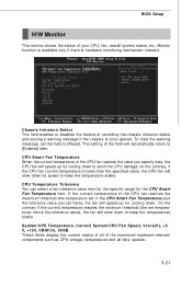
... temperature stable. BIOS Setup H/W Monitor This section shows the status of the monitored hardware devices/ components such as CPU voltage, temperatures and all fans' speeds. 3-21 On the contrary if the current temperature reaches the minimum threshold (the set the field to [Enabled] later. System/CPU Temperature, Current System/CPU Fan Speed, Vcore(V), +5 V, +12V, VBAT(V), 5VSB These items display the current status of all of your CPU, fan, overall system status, etc. Chassis...
... temperature stable. BIOS Setup H/W Monitor This section shows the status of the monitored hardware devices/ components such as CPU voltage, temperatures and all fans' speeds. 3-21 On the contrary if the current temperature reaches the minimum threshold (the set the field to [Enabled] later. System/CPU Temperature, Current System/CPU Fan Speed, Vcore(V), +5 V, +12V, VBAT(V), 5VSB These items display the current status of all of your CPU, fan, overall system status, etc. Chassis...

User Guide
Page 67
... settings control the ratio of your PCI Express card when overclocking, but the stability may cause a stability issue, so changing the memory voltage for long-term purpose is NOT recommended. Please note that the setting options vary according to run at different frequency combinations. PCI Express Voltage PCI Express voltage is used to auto detect the PCI slots. Setting options: [133 MHz]~[450 MHz]. CPU Voltage The settings are used to adjust the CPU clock multiplier (ratio) and CPU core voltage (Vcore). CPU Clock = CPU FSB Frequency * CPU Ratio. Setting options...
... settings control the ratio of your PCI Express card when overclocking, but the stability may cause a stability issue, so changing the memory voltage for long-term purpose is NOT recommended. Please note that the setting options vary according to run at different frequency combinations. PCI Express Voltage PCI Express voltage is used to auto detect the PCI slots. Setting options: [133 MHz]~[450 MHz]. CPU Voltage The settings are used to adjust the CPU clock multiplier (ratio) and CPU core voltage (Vcore). CPU Clock = CPU FSB Frequency * CPU Ratio. Setting options...
User Guide
Page 90
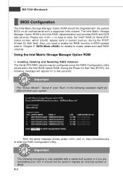
... keys simultaneously to RAID. MS-7246 Mainboard BIOS Configuration The Intel Matrix Storage Manager Option ROM should appear early in system boot-up, during the POST (Power-On Self Test). Please use + keys to create, delete and reset RAID vol um es . Important The following message will appear for a few seconds: Important The "Driver Model", "Serial #" and "Size" in BIOS (please refer to "Chapter 3" SATA Mode for details) to enter the "Intel® RAID...
... keys simultaneously to RAID. MS-7246 Mainboard BIOS Configuration The Intel Matrix Storage Manager Option ROM should appear early in system boot-up, during the POST (Power-On Self Test). Please use + keys to create, delete and reset RAID vol um es . Important The following message will appear for a few seconds: Important The "Driver Model", "Serial #" and "Size" in BIOS (please refer to "Chapter 3" SATA Mode for details) to enter the "Intel® RAID...
User Guide
Page 96
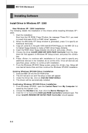
... XP/2000 Setup screen, press the key. down list that appears on the MSI CD to a formatted floppy diskette to be automatically installed. † Confirming Windows XP/2000 Driver Installation 1. Start the installation: Boot from the drop- Under the Driver tab, click on Intel IAA RAID Edition. 4. Press F6 when the message "Press F6 if you need to specify an Additional Device(s). 3. MS-7246 Mainboard Installing Software Install Driver in Windows XP...
... XP/2000 Setup screen, press the key. down list that appears on the MSI CD to a formatted floppy diskette to be automatically installed. † Confirming Windows XP/2000 Driver Installation 1. Start the installation: Boot from the drop- Under the Driver tab, click on Intel IAA RAID Edition. 4. Press F6 when the message "Press F6 if you need to specify an Additional Device(s). 3. MS-7246 Mainboard Installing Software Install Driver in Windows XP...
User Guide
Page 119
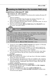
...-ROM drive. 2. W ait until W indows XP/2000 finishes installing devices, regional settings, networking settings, components, and final set of the SCSI and RAID Controllers hardware type. W hen the W indows XP/2000 Setup window is done. 4. The driver disk for JM icron RAID Controller is generated, press key to be accompanied in the mainboard package. From the W indows XP/2000 Setup screen, press the key. Press to a formatted floppy disk. 4. JMicron RAID Installing the RAID Driver (For bootable RAID array) Install Driver...
...-ROM drive. 2. W ait until W indows XP/2000 finishes installing devices, regional settings, networking settings, components, and final set of the SCSI and RAID Controllers hardware type. W hen the W indows XP/2000 Setup window is done. 4. The driver disk for JM icron RAID Controller is generated, press key to be accompanied in the mainboard package. From the W indows XP/2000 Setup screen, press the key. Press to a formatted floppy disk. 4. JMicron RAID Installing the RAID Driver (For bootable RAID array) Install Driver...
User Guide
Page 149
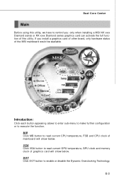
... installing a MSI NX xxxx Diamond series or RX xxxx Diamond series graphics card can activate the full function of the MSI mainboard would be available. Introduction: Click each button appearing above to enter sub-menu to make further configuration or to enable or disable the Dynamic Overclocking Technology. VGA Click VGA button to read current CPU temperature, FSB and CPU clock of graphics card will show below . Dual Core Center Main Before using this utility, we have to remind you install a graphics card...
... installing a MSI NX xxxx Diamond series or RX xxxx Diamond series graphics card can activate the full function of the MSI mainboard would be available. Introduction: Click each button appearing above to enter sub-menu to make further configuration or to enable or disable the Dynamic Overclocking Technology. VGA Click VGA button to read current CPU temperature, FSB and CPU clock of graphics card will show below . Dual Core Center Main Before using this utility, we have to remind you install a graphics card...

