User Guide
Page 9
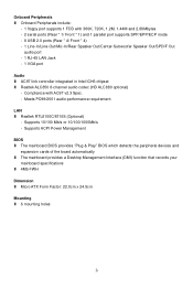
... audio codec (HD ALC880 optional) - Supports ACPI Power Management BIOS l The mainboard BIOS provides "Plug & Play" BIOS which detects the peripheral devices and expansion cards of the board automatically l The mainboard provides a Desktop Management Interface (DMI) function that records your mainboard specifications l 4Mb FWH Dimension l Micro ATX Form Factor: 22.0cm x 24.5cm Mounting l 6 mounting...
... audio codec (HD ALC880 optional) - Supports ACPI Power Management BIOS l The mainboard BIOS provides "Plug & Play" BIOS which detects the peripheral devices and expansion cards of the board automatically l The mainboard provides a Desktop Management Interface (DMI) function that records your mainboard specifications l 4Mb FWH Dimension l Micro ATX Form Factor: 22.0cm x 24.5cm Mounting l 6 mounting...
User Guide
Page 11
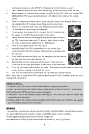
... 10. for the same direction as the arrows shown. 5. Visually inspect if the CPU is in BIOS for details) again and push the clip to protect the contact from lever hinge side. Then cover ..., then remove the CPU Clip with the CPU chamfer, and the square on it to avoid damaging. 5. MSI Reminds You... 1. Use 2 hands to avoid damaging. 4. Please note not to 2GB. Align the two pin... push the clips to be installed. (For the updated supporting memory modules, please visit http://www.msi.com.tw/program/products/mainboard/mbd/pro_mbd_trp_list.php) 5 Align the holes on the CPU & the CPU...
... 10. for the same direction as the arrows shown. 5. Visually inspect if the CPU is in BIOS for details) again and push the clip to protect the contact from lever hinge side. Then cover ..., then remove the CPU Clip with the CPU chamfer, and the square on it to avoid damaging. 5. MSI Reminds You... 1. Use 2 hands to avoid damaging. 4. Please note not to 2GB. Align the two pin... push the clips to be installed. (For the updated supporting memory modules, please visit http://www.msi.com.tw/program/products/mainboard/mbd/pro_mbd_trp_list.php) 5 Align the holes on the CPU & the CPU...
User Guide
Page 13
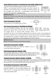
...system cooling fan with Serial ATA 1.0 specifications. If the mainboard has a System Hardware Monitor chipset onboard, you must configure the setting through the BIOS setup to use a specially designed fan with Intel Front Panel I /O Connectivity Design Guide. 7 10 9 Power Switch Reset Switch Power LED HDD... and show a warning message on the screen. The JFP1 is connected to GND. MSI Reminds You... CPUFAN1 can connect to the front panel switches and LEDs. You must enter the BIOS utility and clear the record. All SATA connectors are high-speed Serial ATA interface ports...
...system cooling fan with Serial ATA 1.0 specifications. If the mainboard has a System Hardware Monitor chipset onboard, you must configure the setting through the BIOS setup to use a specially designed fan with Intel Front Panel I /O Connectivity Design Guide. 7 10 9 Power Switch Reset Switch Power LED HDD... and show a warning message on the screen. The JFP1 is connected to GND. MSI Reminds You... CPUFAN1 can connect to the front panel switches and LEDs. You must enter the BIOS utility and clear the record. All SATA connectors are high-speed Serial ATA interface ports...
User Guide
Page 15
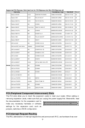
... you to insert the expansion cards to meet your needs. Supported PCI Express VGA Card List for the expansion card, such as jumpers, switches or BIOS configuration. When adding or removing expansion cards, make any necessary hardware or software settings for PCI Express Lite Slot (PCI Express x4) VGA Chip VGA... EN5750 128MB/DDR SDRAM 4.36.20.38.00 OK GeForce PCX5750 Leadtek Winfast PX360 TD 128MB/DDR SDRAM 4.36.20.38.00 OK GeForce PCX5750 MSI MS-8969 128MB/DDR SDRAM 4.36.20.38.12 OK GeForce PCX5900 ELSA Gladiac PCX935 128MB/DDR SGRAM 4.35.20.45.E0 OK PCI (Peripheral...
... you to insert the expansion cards to meet your needs. Supported PCI Express VGA Card List for the expansion card, such as jumpers, switches or BIOS configuration. When adding or removing expansion cards, make any necessary hardware or software settings for PCI Express Lite Slot (PCI Express x4) VGA Chip VGA... EN5750 128MB/DDR SDRAM 4.36.20.38.00 OK GeForce PCX5750 Leadtek Winfast PX360 TD 128MB/DDR SDRAM 4.36.20.38.00 OK GeForce PCX5750 MSI MS-8969 128MB/DDR SDRAM 4.36.20.38.12 OK GeForce PCX5900 ELSA Gladiac PCX935 128MB/DDR SGRAM 4.35.20.45.E0 OK PCI (Peripheral...
User Guide
Page 16
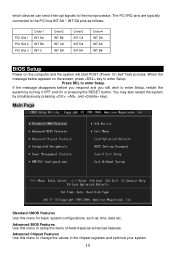
...Slot 1 PCI Slot 2 PCI Slot 3 Order1 INT A# INT B# INT C Order2 INT B# INT C# INT D# Order3 INT C# INT D# INT A# Order4 INT D# INT A# INT B# BIOS Setup Power on the screen, press key to enter Setup, restart the system by simultaneously pressing , , and keys. Advanced Chipset Features Use this menu to...or pressing the RESET button. The PCI IRQ pins are typically connected to setup the items of Award special enhanced features. Advanced BIOS Features Use this menu to the microprocessor. which devices can send interrupt signals to change the values in the chipset registers and ...
...Slot 1 PCI Slot 2 PCI Slot 3 Order1 INT A# INT B# INT C Order2 INT B# INT C# INT D# Order3 INT C# INT D# INT A# Order4 INT D# INT A# INT B# BIOS Setup Power on the screen, press key to enter Setup, restart the system by simultaneously pressing , , and keys. Advanced Chipset Features Use this menu to...or pressing the RESET button. The PCI IRQ pins are typically connected to setup the items of Award special enhanced features. Advanced BIOS Features Use this menu to the microprocessor. which devices can send interrupt signals to change the values in the chipset registers and ...
User Guide
Page 17
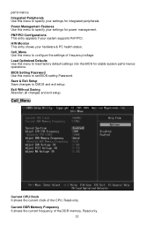
...and exit setup. Cell_Menu Current CPU Clock It shows the current clock of the DDR memory. BIOS Setting Password Use this menu to load factory default settings into the BIOS for power management. Save & Exit Setup Save changes to specify your settings for integrated peripherals.... Load Optimized Defaults Use this menu to configure the settings of frequency/voltage. Power Management Features Use this menu to set BIOS setting Password. performance. Cell_Menu Use this menu to specify your settings for stable system performance operations. Integrated Peripherals Use this menu...
...and exit setup. Cell_Menu Current CPU Clock It shows the current clock of the DDR memory. BIOS Setting Password Use this menu to load factory default settings into the BIOS for power management. Save & Exit Setup Save changes to specify your settings for integrated peripherals.... Load Optimized Defaults Use this menu to configure the settings of frequency/voltage. Power Management Features Use this menu to set BIOS setting Password. performance. Cell_Menu Use this menu to specify your settings for stable system performance operations. Integrated Peripherals Use this menu...
User Guide
Page 46
...;配) - 兼容 AC97 v2.3 PC99/2001 LAN l Realtek RTL8100C/8110S (选配) - 支持 10/100 Mb/s or 10/100/1000Mb/s - 支持 ACPI BIOS l 主板的 BIOS 提供了"Plug & Play l DMI l 4Mb FWH 尺寸 l Micro ATX 22.0cm x 24.5cm 固定孔 l 6 40
...;配) - 兼容 AC97 v2.3 PC99/2001 LAN l Realtek RTL8100C/8110S (选配) - 支持 10/100 Mb/s or 10/100/1000Mb/s - 支持 ACPI BIOS l 主板的 BIOS 提供了"Plug & Play l DMI l 4Mb FWH 尺寸 l Micro ATX 22.0cm x 24.5cm 固定孔 l 6 40
User Guide
Page 50
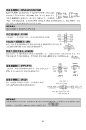
JCOM1 12 SIN SOUT GND DTR DSR RTS CTS IrDA JIR2 RI KEY 9 10 IrDA BIOS IR 功能.JIR1 是和 Intel 的 I/O IRTX JCASE2 2-pin BIOS 2 GND 1 CINTRU JFP1/JFP2 JFP1 是和 Intel 的 I/O 10 9 Power Switch Reset Switch Power LED HDD LED 21 JFP1 JAUD1 Intel®的 I/O AUD_RET_R...
JCOM1 12 SIN SOUT GND DTR DSR RTS CTS IrDA JIR2 RI KEY 9 10 IrDA BIOS IR 功能.JIR1 是和 Intel 的 I/O IRTX JCASE2 2-pin BIOS 2 GND 1 CINTRU JFP1/JFP2 JFP1 是和 Intel 的 I/O 10 9 Power Switch Reset Switch Power LED HDD LED 21 JFP1 JAUD1 Intel®的 I/O AUD_RET_R...
User Guide
Page 54
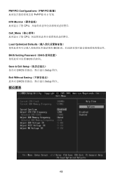
PNP/PCI Configurations(PNP/PCI PnP/PCI H/W Monitor CPU Cell_Menu CPU Load Optimized Defaults BIOS BIOS Setting Password(BIOS BIOS Save & Exit Setup CMOS Setup 程序. Exit Without Saving CMOS Setup 程序.. 核心菜单 48
PNP/PCI Configurations(PNP/PCI PnP/PCI H/W Monitor CPU Cell_Menu CPU Load Optimized Defaults BIOS BIOS Setting Password(BIOS BIOS Save & Exit Setup CMOS Setup 程序. Exit Without Saving CMOS Setup 程序.. 核心菜单 48

User Guide
Page 62
GND (2)VCC (1)VCC USB0- GND USB0+ USB0C(10) Key(9) MSI VC C 和 GND 56 CPU MSI CPU 風扇。 JCOM1 IrDA JIR2 SOUT GND RTS RI 12 9 10 SIN DTR DSR CTS KEY IrDA BIOS JIR1 Intel IRTX JCASE2 2 GND 2-pin 1 CINTRU BIOS 10 9 Speaker JFP1/JFP2 LED JFP1 Intel Power Switch Power Reset...
GND (2)VCC (1)VCC USB0- GND USB0+ USB0C(10) Key(9) MSI VC C 和 GND 56 CPU MSI CPU 風扇。 JCOM1 IrDA JIR2 SOUT GND RTS RI 12 9 10 SIN DTR DSR CTS KEY IrDA BIOS JIR1 Intel IRTX JCASE2 2 GND 2-pin 1 CINTRU BIOS 10 9 Speaker JFP1/JFP2 LED JFP1 Intel Power Switch Power Reset...
User Guide
Page 65
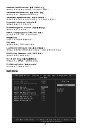
Standard CMOS Features(標準 CMOS Advanced BIOS Features(進階 BIOS Award Advanced Chipset Features Integrated Peripherals Power Management Features PNP/PCI Configurations(PNP/PCI PnP/PCI H/W Monitor Cell_Menu CPU Load Optimized Defaults BIOS BIOS Setting Password(設定 BIOS BIOS 密碼。 Save & Exit Setup CMOS Exit Without Saving Cell_Menu 59
Standard CMOS Features(標準 CMOS Advanced BIOS Features(進階 BIOS Award Advanced Chipset Features Integrated Peripherals Power Management Features PNP/PCI Configurations(PNP/PCI PnP/PCI H/W Monitor Cell_Menu CPU Load Optimized Defaults BIOS BIOS Setting Password(設定 BIOS BIOS 密碼。 Save & Exit Setup CMOS Exit Without Saving Cell_Menu 59


