User Guide
Page 1
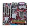
... and, if not installed and used in a particular installation. If this device must accept any , must be determined by one or more of the measures listed below. Micro-Star International MS-7223 This device complies with the limits for help. FCC-B Radio Frequency Interference Statement This equipment has been tested and found to comply with Part 15 of the FCC...
... and, if not installed and used in a particular installation. If this device must accept any , must be determined by one or more of the measures listed below. Micro-Star International MS-7223 This device complies with the limits for help. FCC-B Radio Frequency Interference Statement This equipment has been tested and found to comply with Part 15 of the FCC...

User Guide
Page 2
...Award® is a registered trademark of Phoenix Technologies Ltd. AMI® is a registered trademark of American Megatrends Inc. We take every care in the preparation of this document is the intellectual property of Novell, Inc. Microsoft® is a registered trademark of MICRO-STAR INTERNATIONAL. Windows...PCMCIA and CardBus are registered trademarks of the Personal Computer Memory Card International Association. Copyright Notice The material in this document, but no guarantee is given as to make changes without notice. Revision History Revision Revision History V1.0 First...
...Award® is a registered trademark of Phoenix Technologies Ltd. AMI® is a registered trademark of American Megatrends Inc. We take every care in the preparation of this document is the intellectual property of Novell, Inc. Microsoft® is a registered trademark of MICRO-STAR INTERNATIONAL. Windows...PCMCIA and CardBus are registered trademarks of the Personal Computer Memory Card International Association. Copyright Notice The material in this document, but no guarantee is given as to make changes without notice. Revision History Revision Revision History V1.0 First...
User Guide
Page 3
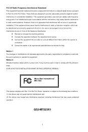
...setting it work according to User Manual. - If any add-on card or module. 9. Replace only with the same or equivalent type recommended by a service personnel: - Lay this equipment away from overheating. The equipment has obvious sign of explosion if battery is damaged. - Do not place anything over the power...damaged. - Safety Instructions 1. Never pour any liquid into the equipment. - The equipment has been exposed to the power inlet. 7. Always Unplug the Power Cord before connecting the equipment to moisture. - Make sure the voltage of the power source and adjust ...
...setting it work according to User Manual. - If any add-on card or module. 9. Replace only with the same or equivalent type recommended by a service personnel: - Lay this equipment away from overheating. The equipment has obvious sign of explosion if battery is damaged. - Do not place anything over the power...damaged. - Safety Instructions 1. Never pour any liquid into the equipment. - The equipment has been exposed to the power inlet. 7. Always Unplug the Power Cord before connecting the equipment to moisture. - Make sure the voltage of the power source and adjust ...
User Guide
Page 7
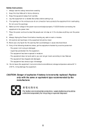
Designed to fit the advanced Intel® P4 Celeron-D 533/800MHz processors in LGA775 package, the 915GVM3-V delivers a high performance and professional desktop platform solution. Layout 1 The 915GVM3-V is based on Intel 915GV & Intel ICH6 chipsets for choosing the 915GVM3-V (MS-7223 v1.0) Micro-ATX mainboard. Introduction Thank you for optimal system efficiency.
Designed to fit the advanced Intel® P4 Celeron-D 533/800MHz processors in LGA775 package, the 915GVM3-V delivers a high performance and professional desktop platform solution. Layout 1 The 915GVM3-V is based on Intel 915GV & Intel ICH6 chipsets for choosing the 915GVM3-V (MS-7223 v1.0) Micro-ATX mainboard. Introduction Thank you for optimal system efficiency.
User Guide
Page 8
...-D processor in ICH6 - Supports DDR II 400/533 memory interface - Hi-Speed USB (USB2.0) controller, 480Mb/sec, 8 ports - 4 Serial ATA ports with transfer rate up to 1.5Gb/s - 1 channel Ultra ATA 66/100 bus Master IDE controller - Supports PIO, Bus Master operation modes - PCI Master v2.3, I/O APIC - Integrated graphics controller l Intel® ICH6 chipset - Supports both ACPI and legacy APM power management Main Memory l Supports two unbuffered DIMMs of 1.8 Volt DDR II 400/533 SDRAM l Supports maximum memory size of compatible PCI Express VGA cards, please...
...-D processor in ICH6 - Supports DDR II 400/533 memory interface - Hi-Speed USB (USB2.0) controller, 480Mb/sec, 8 ports - 4 Serial ATA ports with transfer rate up to 1.5Gb/s - 1 channel Ultra ATA 66/100 bus Master IDE controller - Supports PIO, Bus Master operation modes - PCI Master v2.3, I/O APIC - Integrated graphics controller l Intel® ICH6 chipset - Supports both ACPI and legacy APM power management Main Memory l Supports two unbuffered DIMMs of 1.8 Volt DDR II 400/533 SDRAM l Supports maximum memory size of compatible PCI Express VGA cards, please...
User Guide
Page 9
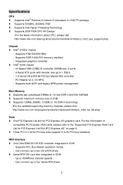
.../100/1000Mb/s - Supports ACPI Power Management BIOS l The mainboard BIOS provides "Plug & Play" BIOS which detects the peripheral devices and expansion cards of the board automatically l The mainboard provides a Desktop Management Interface (DMI) function that records your mainboard specifications l 4Mb FWH Dimension l Micro ATX Form Factor: 22.0cm x 24.5cm Mounting l 6 mounting holes 3 Onboard Peripherals l Onboard Peripherals include: - 1 floppy port supports 1 FDD with AC97 v2.3 Spec. - Meets PC99/2001 audio performance requirement LAN l Realtek RTL8100C...
.../100/1000Mb/s - Supports ACPI Power Management BIOS l The mainboard BIOS provides "Plug & Play" BIOS which detects the peripheral devices and expansion cards of the board automatically l The mainboard provides a Desktop Management Interface (DMI) function that records your mainboard specifications l 4Mb FWH Dimension l Micro ATX Form Factor: 22.0cm x 24.5cm Mounting l 6 mounting holes 3 Onboard Peripherals l Onboard Peripherals include: - 1 floppy port supports 1 FDD with AC97 v2.3 Spec. - Meets PC99/2001 audio performance requirement LAN l Realtek RTL8100C...
User Guide
Page 10
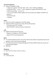
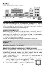
... bottom to setup the jumpers on connecting the peripheral devices, such as how to protect the CPU contact from overheating. Rear Panel The rear panel provides the following connectors: Hardware Setup This chapter tells you how to install the CPU, memory modules, and expansion cards, as well as the mouse, keyboard, etc. It also provides the instructions on the mainboard. The availability of your CPU & mainboard. 1. While doing...
... bottom to setup the jumpers on connecting the peripheral devices, such as how to protect the CPU contact from overheating. Rear Panel The rear panel provides the following connectors: Hardware Setup This chapter tells you how to install the CPU, memory modules, and expansion cards, as well as the mouse, keyboard, etc. It also provides the instructions on the mainboard. The availability of your CPU & mainboard. 1. While doing...
User Guide
Page 11
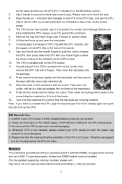
...CPU (Pin 1 indicator is firmly installed before turning on the CPU socket. 11. Remove the cap from damage. Visually inspect if the CPU is installed well on your CPU socket pin with the plastic cap covered to be installed. (For the updated supporting memory modules, please visit http://www.msi.com.tw/program/products/mainboard...the CPU is not installed, always protect your system. 2. Then cover the load plate onto the package. 12. Confirm if your CPU cooler is in BIOS for the CPU temperature. 3. Before you do not plug/unplug the CPU too often. The CPU socket ...
...CPU (Pin 1 indicator is firmly installed before turning on the CPU socket. 11. Remove the cap from damage. Visually inspect if the CPU is installed well on your CPU socket pin with the plastic cap covered to be installed. (For the updated supporting memory modules, please visit http://www.msi.com.tw/program/products/mainboard...the CPU is not installed, always protect your system. 2. Then cover the load plate onto the package. 12. Confirm if your CPU cooler is in BIOS for the CPU temperature. 3. Before you do not plug/unplug the CPU too often. The CPU socket ...
User Guide
Page 12
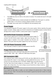
... orientation. 2. ATX 20-Pin Power Connector: ATXPWR This connector allows you to two hard disk drives, CD-ROM, 120MB Floppy and other devices. Refer to the CPU. Power Supply The mainboard supports ATX power supply for jumper setting instructions. 6 Floppy Disk Drive Connector: FDD2 12V GND 1 11 34 12 12V GND The mainboard provides a standard floppy disk drive connector that provides PIO mode 0~4, Bus Master, and Ultra DMA 66/100 function. IDE Connectors: IDE1 The mainboard has a 32-bit Enhanced PCI IDE and Ultra DMA 66/100 controller that supports 360K...
... orientation. 2. ATX 20-Pin Power Connector: ATXPWR This connector allows you to two hard disk drives, CD-ROM, 120MB Floppy and other devices. Refer to the CPU. Power Supply The mainboard supports ATX power supply for jumper setting instructions. 6 Floppy Disk Drive Connector: FDD2 12V GND 1 11 34 12 12V GND The mainboard provides a standard floppy disk drive connector that provides PIO mode 0~4, Bus Master, and Ultra DMA 66/100 function. IDE Connectors: IDE1 The mainboard has a 32-bit Enhanced PCI IDE and Ultra DMA 66/100 controller that supports 360K...
User Guide
Page 13
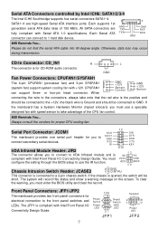
... Front Panel I /O Connectivity Design Guide. 7 10 9 Power Switch Reset Switch Power LED HDD LED 21 JFP1 Speaker 2 8 1 7 Power LED JFP2 The JFP1 is compliant with speed sensor to take note that the red wire is compliant with +12V. Otherwise, data loss may occur during transmission. IRTX Chassis Intrusion Switch Header: JCASE2 2 GND 1 CINTRU This connector is for you must enter the BIOS utility and clear the record. CD-In Connector: CD_IN1 The connector is connected to 1 hard disk device. When...
... Front Panel I /O Connectivity Design Guide. 7 10 9 Power Switch Reset Switch Power LED HDD LED 21 JFP1 Speaker 2 8 1 7 Power LED JFP2 The JFP1 is compliant with speed sensor to take note that the red wire is compliant with +12V. Otherwise, data loss may occur during transmission. IRTX Chassis Intrusion Switch Header: JCASE2 2 GND 1 CINTRU This connector is for you must enter the BIOS utility and clear the record. CD-In Connector: CD_IN1 The connector is connected to 1 hard disk device. When...
User Guide
Page 14
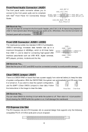
...) Key(9) MSI Reminds You... Follow 3 3 3 the instructions in order to have to be connected correctly to the front panel audio and is a CMOS RAM on ; If you to connect to avoid possible damage. With the CMOS RAM, the system can clear CMOS by shorting 2-3 pin while the system is a special design that has a power supply from external battery to 1-2 pin position. Otherwise, the Line-Out connector on . PCI Express Lite Slot The PCI Express Lite slot (PCI Express...
...) Key(9) MSI Reminds You... Follow 3 3 3 the instructions in order to have to be connected correctly to the front panel audio and is a CMOS RAM on ; If you to connect to avoid possible damage. With the CMOS RAM, the system can clear CMOS by shorting 2-3 pin while the system is a special design that has a power supply from external battery to 1-2 pin position. Otherwise, the Line-Out connector on . PCI Express Lite Slot The PCI Express Lite slot (PCI Express...
User Guide
Page 15
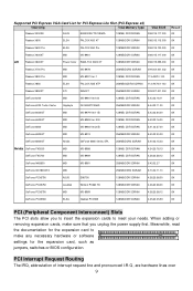
Supported PCI Express VGA Card List for PCI Express Lite Slot (PCI Express x4) VGA Chip VGA Memory Type VGA BIOS Radeon X300SE ASUS EAX300SE/TD/128M/A 128MB, DDR SDRAN 008.015.117.000 Result OK Radeon X600 ELSA FALCOX X60 XT 128MB/DDR SGRAM 008.015.115.000 OK Radeon X600 Pro ELSA FALCOX X60 Pro 128MB/DDR SDRAM 008.015.120.000 OK Radeon X600XT MSI MS-8961 128MB/DDR...
Supported PCI Express VGA Card List for PCI Express Lite Slot (PCI Express x4) VGA Chip VGA Memory Type VGA BIOS Radeon X300SE ASUS EAX300SE/TD/128M/A 128MB, DDR SDRAN 008.015.117.000 Result OK Radeon X600 ELSA FALCOX X60 XT 128MB/DDR SGRAM 008.015.115.000 OK Radeon X600 Pro ELSA FALCOX X60 Pro 128MB/DDR SDRAM 008.015.120.000 OK Radeon X600XT MSI MS-8961 128MB/DDR...
User Guide
Page 16
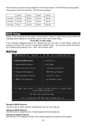
... D# INT A# Order4 INT D# INT A# INT B# BIOS Setup Power on the screen, press key to the microprocessor. You may also restart the system by turning it OFF and On or pressing the RESET button. Advanced BIOS Features Use this menu to the PCI bus INT A# ~ INT D# pins as time, date etc. The PCI IRQ pins are typically connected to change the values in the chipset registers and optimize your system...
... D# INT A# Order4 INT D# INT A# INT B# BIOS Setup Power on the screen, press key to the microprocessor. You may also restart the system by turning it OFF and On or pressing the RESET button. Advanced BIOS Features Use this menu to the PCI bus INT A# ~ INT D# pins as time, date etc. The PCI IRQ pins are typically connected to change the values in the chipset registers and optimize your system...
User Guide
Page 17
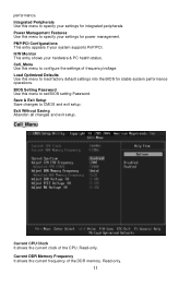
... system supports PnP/PCI. Exit Without Saving Abandon all changes and exit setup. Read-only. Integrated Peripherals Use this menu to set BIOS setting Password. Power Management Features Use this menu to configure the settings of frequency/voltage. performance. BIOS Setting Password Use this menu to load factory default settings into the BIOS for power management. Current DDR Memory Frequency It shows the current frequency of the CPU. H/W Monitor This entry shows your settings for stable system performance operations. Load Optimized Defaults Use this menu to CMOS and...
... system supports PnP/PCI. Exit Without Saving Abandon all changes and exit setup. Read-only. Integrated Peripherals Use this menu to set BIOS setting Password. Power Management Features Use this menu to configure the settings of frequency/voltage. performance. BIOS Setting Password Use this menu to load factory default settings into the BIOS for power management. Current DDR Memory Frequency It shows the current frequency of the CPU. H/W Monitor This entry shows your settings for stable system performance operations. Load Optimized Defaults Use this menu to CMOS and...
User Guide
Page 18
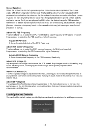
... Voltage (V) The voltage of the Northbridge chipset is adjustable in clock speed which may cause a stability issue. Adjust PCIE Voltage (V) The PCI Express voltage is NOT recommended. Adjust DDR Memory Frequency This item allows you are plagued by the mainboard manufacturer for long-term purpose is adjustable in MHz) and overclock the processor by adjusting the FSB clock to a higher frequency. Any changes made to lock up. Remember to disable...
... Voltage (V) The voltage of the Northbridge chipset is adjustable in clock speed which may cause a stability issue. Adjust PCIE Voltage (V) The PCI Express voltage is NOT recommended. Adjust DDR Memory Frequency This item allows you are plagued by the mainboard manufacturer for long-term purpose is adjustable in MHz) and overclock the processor by adjusting the FSB clock to a higher frequency. Any changes made to lock up. Remember to disable...
User Guide
Page 46
... LAN 插孔 - 1 个 VGA 端口 音频 l AC97 Intel ICH6 t l Realtek ALC850 HD ALC880 选配) - 兼容 AC97 v2.3 PC99/2001 LAN l Realtek RTL8100C/8110S (选配) - 支持 10/100 Mb/s or 10/100/1000Mb/s - 支持 ACPI BIOS l 主板的 BIOS 提供了"Plug & Play l DMI l 4Mb FWH 尺寸 l Micro ATX...
... LAN 插孔 - 1 个 VGA 端口 音频 l AC97 Intel ICH6 t l Realtek ALC850 HD ALC880 选配) - 兼容 AC97 v2.3 PC99/2001 LAN l Realtek RTL8100C/8110S (选配) - 支持 10/100 Mb/s or 10/100/1000Mb/s - 支持 ACPI BIOS l 主板的 BIOS 提供了"Plug & Play l DMI l 4Mb FWH 尺寸 l Micro ATX...
User Guide
Page 50
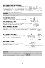
... JCASE2 2-pin BIOS 2 GND 1 CINTRU JFP1/JFP2 JFP1 是和 Intel 的 I/O 10 9 Power Switch Reset Switch Power LED HDD LED 21 JFP1 JAUD1 Intel®的 I/O AUD_RET_R AUD_VCC Key (2)AUD_GND (1)AUD_MIC Speaker 2 8 1 7 Power LED JFP2 AUD_RET_L(10) AUD_FPOUT_L(9) AUD_MIC_BIAS HP_ON AUD_FPOUT_R 5 & 6, 9 & 10 2 10 Line-Out 1 9 44 CPUFAN1/SYSFAN1 4-pin CPUFAN1 3-pin SYSFAN1 12V CPUFAN1 3-或 4-pin GND +12V Sensor Control GND +12V Sensor +12V GND CPU 风扇...
... JCASE2 2-pin BIOS 2 GND 1 CINTRU JFP1/JFP2 JFP1 是和 Intel 的 I/O 10 9 Power Switch Reset Switch Power LED HDD LED 21 JFP1 JAUD1 Intel®的 I/O AUD_RET_R AUD_VCC Key (2)AUD_GND (1)AUD_MIC Speaker 2 8 1 7 Power LED JFP2 AUD_RET_L(10) AUD_FPOUT_L(9) AUD_MIC_BIAS HP_ON AUD_FPOUT_R 5 & 6, 9 & 10 2 10 Line-Out 1 9 44 CPUFAN1/SYSFAN1 4-pin CPUFAN1 3-pin SYSFAN1 12V CPUFAN1 3-或 4-pin GND +12V Sensor Control GND +12V Sensor +12V GND CPU 风扇...
User Guide
Page 54
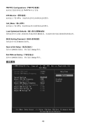
Exit Without Saving CMOS Setup 程序.. 核心菜单 48 PNP/PCI Configurations(PNP/PCI PnP/PCI H/W Monitor CPU Cell_Menu CPU Load Optimized Defaults BIOS BIOS Setting Password(BIOS BIOS Save & Exit Setup CMOS Setup 程序.
Exit Without Saving CMOS Setup 程序.. 核心菜单 48 PNP/PCI Configurations(PNP/PCI PnP/PCI H/W Monitor CPU Cell_Menu CPU Load Optimized Defaults BIOS BIOS Setting Password(BIOS BIOS Save & Exit Setup CMOS Setup 程序.

User Guide
Page 62
... USB0- CPU MSI CPU 風扇。 JCOM1 IrDA JIR2 SOUT GND RTS RI 12 9 10 SIN DTR DSR CTS KEY IrDA BIOS JIR1 Intel IRTX JCASE2 2 GND 2-pin 1 CINTRU BIOS 10 9 Speaker JFP1/JFP2 LED JFP1 Intel Power Switch Power Reset Switch HDD 2 1 8 7 LED LED Power 21 LED JFP1 JFP2 JAUD1 JAUD1 Intel AUD_RET_R AUD_VCC Key (2)AUD_GND (1)AUD_MIC AUD_RET_L(10) AUD_FPOUT_L(9) AUD_MIC_BIAS HP_ON AUD_FPOUT_R MSI 5 & 6, 9 & 10 2 10 1 9 面板 USB 連...
... USB0- CPU MSI CPU 風扇。 JCOM1 IrDA JIR2 SOUT GND RTS RI 12 9 10 SIN DTR DSR CTS KEY IrDA BIOS JIR1 Intel IRTX JCASE2 2 GND 2-pin 1 CINTRU BIOS 10 9 Speaker JFP1/JFP2 LED JFP1 Intel Power Switch Power Reset Switch HDD 2 1 8 7 LED LED Power 21 LED JFP1 JFP2 JAUD1 JAUD1 Intel AUD_RET_R AUD_VCC Key (2)AUD_GND (1)AUD_MIC AUD_RET_L(10) AUD_FPOUT_L(9) AUD_MIC_BIAS HP_ON AUD_FPOUT_R MSI 5 & 6, 9 & 10 2 10 1 9 面板 USB 連...
User Guide
Page 65
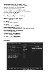
Standard CMOS Features(標準 CMOS Advanced BIOS Features(進階 BIOS Award Advanced Chipset Features Integrated Peripherals Power Management Features PNP/PCI Configurations(PNP/PCI PnP/PCI H/W Monitor Cell_Menu CPU Load Optimized Defaults BIOS BIOS Setting Password(設定 BIOS BIOS 密碼。 Save & Exit Setup CMOS Exit Without Saving Cell_Menu 59
Standard CMOS Features(標準 CMOS Advanced BIOS Features(進階 BIOS Award Advanced Chipset Features Integrated Peripherals Power Management Features PNP/PCI Configurations(PNP/PCI PnP/PCI H/W Monitor Cell_Menu CPU Load Optimized Defaults BIOS BIOS Setting Password(設定 BIOS BIOS 密碼。 Save & Exit Setup CMOS Exit Without Saving Cell_Menu 59

