User Guide
Page 8
... 66/100 IDE controller integrated in LGA775 package l Supports 533MHz, 800MHz FSB l Supports Intel Hyper-Threading Technology l Supports 2005 FMA CPU VR Design (For the latest information about CPU, please visit http://www.msi.com.tw/program/products/mainboard/mbd/pro_mbd_cpu_support.php) Chipset l Intel® 915GV chipset - For the information of 2GB l Supports...
... 66/100 IDE controller integrated in LGA775 package l Supports 533MHz, 800MHz FSB l Supports Intel Hyper-Threading Technology l Supports 2005 FMA CPU VR Design (For the latest information about CPU, please visit http://www.msi.com.tw/program/products/mainboard/mbd/pro_mbd_cpu_support.php) Chipset l Intel® 915GV chipset - For the information of 2GB l Supports...
User Guide
Page 10
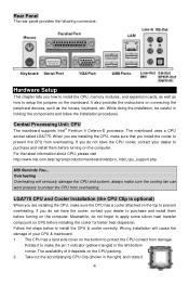
...also provides the instructions on the mainboard. When you install the cooler to protect the CPU from overheating. For the latest information about CPU, please visit http://www.msi.com.tw/program/products/mainboard/mbd/pro_mbd_cpu_support.php. Meanwhile, do not forget to apply ... install them before turning on the CPU packing. 2. Wrong installation will seriously damage the CPU and system; Take out the accompanying CPU Clip (shown in holding the components and follow the installation procedures. MSI Reminds You... Central Processing Unit: CPU The mainboard supports Intel® Pentium...
...also provides the instructions on the mainboard. When you install the cooler to protect the CPU from overheating. For the latest information about CPU, please visit http://www.msi.com.tw/program/products/mainboard/mbd/pro_mbd_cpu_support.php. Meanwhile, do not forget to apply ... install them before turning on the CPU packing. 2. Wrong installation will seriously damage the CPU and system; Take out the accompanying CPU Clip (shown in holding the components and follow the installation procedures. MSI Reminds You... Central Processing Unit: CPU The mainboard supports Intel® Pentium...
User Guide
Page 11
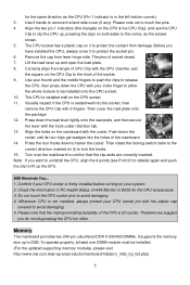
...four clips get wedged into the socket, then remove the CPU Clip with the CPU chamfer, and the square on the CPU & the CPU Clip), and use the CPU Clip to be installed. (For the updated supporting memory modules, please visit http://www.msi.com.tw/program/products/mainboard/mbd/pro_mbd_trp_list.php) 5 Note...marked on the mainboard with the hook under retention tab. 13. MSI Reminds You... 1. Check the information in BIOS for the CPU temperature. 3. Lift the load lever up to protect the socket pin. 6. Confirm if your CPU cooler is installed well on your thumb and the middle fingers to...
...four clips get wedged into the socket, then remove the CPU Clip with the CPU chamfer, and the square on the CPU & the CPU Clip), and use the CPU Clip to be installed. (For the updated supporting memory modules, please visit http://www.msi.com.tw/program/products/mainboard/mbd/pro_mbd_trp_list.php) 5 Note...marked on the mainboard with the hook under retention tab. 13. MSI Reminds You... 1. Check the information in BIOS for the CPU temperature. 3. Lift the load lever up to protect the socket pin. 6. Confirm if your CPU cooler is installed well on your thumb and the middle fingers to...
User Guide
Page 12
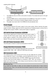
...a Master and a Slave drive. The first hard drive should always be caused. MSI Reminds You... ATX 20-Pin Power Connector: ATXPWR This connector allows you must configure second hard drive to the CPU. A 300W or above power supply is inserted in the proper orientation and the pins...3. Installing DDR II Modules Volt Notch 1. The DIMM has only one notch on cable, you to IDE1. Power Supply The mainboard supports ATX power supply for jumper setting instructions. 6 The module will automatically close. IDE Connectors: IDE1 The mainboard has a 32-bit Enhanced PCI ...
...a Master and a Slave drive. The first hard drive should always be caused. MSI Reminds You... ATX 20-Pin Power Connector: ATXPWR This connector allows you must configure second hard drive to the CPU. A 300W or above power supply is inserted in the proper orientation and the pins...3. Installing DDR II Modules Volt Notch 1. The DIMM has only one notch on cable, you to IDE1. Power Supply The mainboard supports ATX power supply for jumper setting instructions. 6 The module will automatically close. IDE Connectors: IDE1 The mainboard has a 32-bit Enhanced PCI ...
User Guide
Page 13
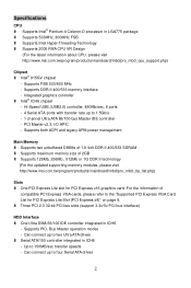
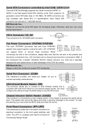
... Design Guide. Front Panel Connectors: JFP1/JFP2 The mainboard provides two front panel connectors for proper CPU cooling fan. Each Serial ATA TXN RXN GND connector can support three- MSI Reminds You... All SATA connectors are high-speed Serial ATA interface ports. SOUT GND RTS RI ...hard disk device. The system will be connected to a 2-pin chassis switch. Each supports 1st GND generation serial ATA data rates of the CPU fan control. Serial ATA Connectors controlled by Intel ICH6: SATA1/2/3/4 The Intel ICH6 Southbridge supports four serial connectors SATA1~4. 1 7 SATA1~4 ...
... Design Guide. Front Panel Connectors: JFP1/JFP2 The mainboard provides two front panel connectors for proper CPU cooling fan. Each Serial ATA TXN RXN GND connector can support three- MSI Reminds You... All SATA connectors are high-speed Serial ATA interface ports. SOUT GND RTS RI ...hard disk device. The system will be connected to a 2-pin chassis switch. Each supports 1st GND generation serial ATA data rates of the CPU fan control. Serial ATA Connectors controlled by Intel ICH6: SATA1/2/3/4 The Intel ICH6 Southbridge supports four serial connectors SATA1~4. 1 7 SATA1~4 ...
User Guide
Page 17
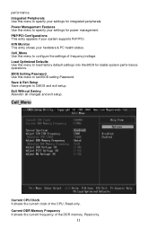
... for stable system performance operations. Exit Without Saving Abandon all changes and exit setup. Current DDR Memory Frequency It shows the current frequency of the CPU. Cell_Menu Use this menu to configure the settings of frequency/voltage. Read-only. Load Optimized Defaults Use this menu to CMOS and exit setup. Cell_Menu...
... for stable system performance operations. Exit Without Saving Abandon all changes and exit setup. Current DDR Memory Frequency It shows the current frequency of the CPU. Cell_Menu Use this menu to configure the settings of frequency/voltage. Read-only. Load Optimized Defaults Use this menu to CMOS and exit setup. Cell_Menu...
User Guide
Page 18
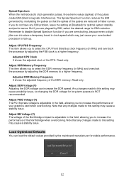
...may cause a stability issue. Adjust PCIE Voltage (V) The PCI Express voltage is adjustable in the field, allowing you to select the CPU Front Side Bus clock frequency (in MHz) and overclock the processor by adjusting the FSB clock to increase the performance of your overclocked... Interference). Adjusted DDR Memory Frequency It shows the adjusted frequency of the CPU. Adjust DDR Voltage (V) Adjusting the DDR voltage can increase the DDR speed. Any changes made to lock up. Spread Spectrum When the motherboard's clock generator pulses, the extreme values (spikes) of the pulses are...
...may cause a stability issue. Adjust PCIE Voltage (V) The PCI Express voltage is adjustable in the field, allowing you to select the CPU Front Side Bus clock frequency (in MHz) and overclock the processor by adjusting the FSB clock to increase the performance of your overclocked... Interference). Adjusted DDR Memory Frequency It shows the adjusted frequency of the CPU. Adjust DDR Voltage (V) Adjusting the DDR voltage can increase the DDR speed. Any changes made to lock up. Spread Spectrum When the motherboard's clock generator pulses, the extreme values (spikes) of the pulses are...
User Guide
Page 50
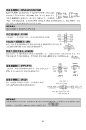
CPUFAN1/SYSFAN1 4-pin CPUFAN1 3-pin SYSFAN1 12V CPUFAN1 3-或 4-pin GND +12V Sensor Control GND +12V Sensor +12V GND CPU 风扇. JCOM1 12 SIN SOUT GND DTR DSR RTS CTS IrDA JIR2 RI KEY 9 10 IrDA BIOS IR 功能.JIR1 是和 Intel &#...
CPUFAN1/SYSFAN1 4-pin CPUFAN1 3-pin SYSFAN1 12V CPUFAN1 3-或 4-pin GND +12V Sensor Control GND +12V Sensor +12V GND CPU 风扇. JCOM1 12 SIN SOUT GND DTR DSR RTS CTS IrDA JIR2 RI KEY 9 10 IrDA BIOS IR 功能.JIR1 是和 Intel &#...
User Guide
Page 54
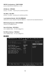
PNP/PCI Configurations(PNP/PCI PnP/PCI H/W Monitor CPU Cell_Menu CPU Load Optimized Defaults BIOS BIOS Setting Password(BIOS BIOS Save & Exit Setup CMOS Setup 程序. Exit Without Saving CMOS Setup 程序.. 核心菜单 48
PNP/PCI Configurations(PNP/PCI PnP/PCI H/W Monitor CPU Cell_Menu CPU Load Optimized Defaults BIOS BIOS Setting Password(BIOS BIOS Save & Exit Setup CMOS Setup 程序. Exit Without Saving CMOS Setup 程序.. 核心菜单 48

User Guide
Page 62
CPU MSI CPU 風扇。 JCOM1 IrDA JIR2 SOUT GND RTS RI 12 9 10 SIN DTR DSR CTS KEY IrDA BIOS JIR1 Intel IRTX JCASE2 2 GND 2-pin 1 ... Power Reset Switch HDD 2 1 8 7 LED LED Power 21 LED JFP1 JFP2 JAUD1 JAUD1 Intel AUD_RET_R AUD_VCC Key (2)AUD_GND (1)AUD_MIC AUD_RET_L(10) AUD_FPOUT_L(9) AUD_MIC_BIAS HP_ON AUD_FPOUT_R MSI 5 & 6, 9 & 10 2 10 1 9 面板 USB 連接器: JUSB1/ JUSB2 USB2.0 USB2.0 480Mbps,為 USB1.1 的 40 USB USB MP3 USB1+ USB1- GND USB0...
CPU MSI CPU 風扇。 JCOM1 IrDA JIR2 SOUT GND RTS RI 12 9 10 SIN DTR DSR CTS KEY IrDA BIOS JIR1 Intel IRTX JCASE2 2 GND 2-pin 1 ... Power Reset Switch HDD 2 1 8 7 LED LED Power 21 LED JFP1 JFP2 JAUD1 JAUD1 Intel AUD_RET_R AUD_VCC Key (2)AUD_GND (1)AUD_MIC AUD_RET_L(10) AUD_FPOUT_L(9) AUD_MIC_BIAS HP_ON AUD_FPOUT_R MSI 5 & 6, 9 & 10 2 10 1 9 面板 USB 連接器: JUSB1/ JUSB2 USB2.0 USB2.0 480Mbps,為 USB1.1 的 40 USB USB MP3 USB1+ USB1- GND USB0...
User Guide
Page 65
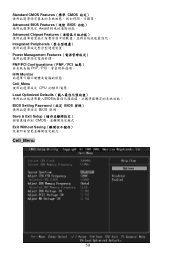
Standard CMOS Features(標準 CMOS Advanced BIOS Features(進階 BIOS Award Advanced Chipset Features Integrated Peripherals Power Management Features PNP/PCI Configurations(PNP/PCI PnP/PCI H/W Monitor Cell_Menu CPU Load Optimized Defaults BIOS BIOS Setting Password(設定 BIOS BIOS 密碼。 Save & Exit Setup CMOS Exit Without Saving Cell_Menu 59
Standard CMOS Features(標準 CMOS Advanced BIOS Features(進階 BIOS Award Advanced Chipset Features Integrated Peripherals Power Management Features PNP/PCI Configurations(PNP/PCI PnP/PCI H/W Monitor Cell_Menu CPU Load Optimized Defaults BIOS BIOS Setting Password(設定 BIOS BIOS 密碼。 Save & Exit Setup CMOS Exit Without Saving Cell_Menu 59

