

LA400 Manual
Page 2
...) WIRING Connect the Gate Operator (Gate 1) to the Control Box Set the Bipart Delay (Model LA400-S Only) Connect the Gate Operator (Gate 2) to the Control Box (Model LA400-S Only) Junction Box (Model LA400-S Only) Connect Transformer to Control Board Earth Ground Rod Installation (Optional) Connect Batteries 1-6 1 ...Loop Inputs Photo/Edge Inputs (P6-7-8 and 9) Safety Accessories for Secondary Entrapment Protection OPERATION AND MAINTENANCE Reset Button Remote Control Manual Release Maintenance TROUBLESHOOTING Basic Control Board Layout Wiring Diagram Diagnostic Codes Troubleshooting Chart ...
...) WIRING Connect the Gate Operator (Gate 1) to the Control Box Set the Bipart Delay (Model LA400-S Only) Connect the Gate Operator (Gate 2) to the Control Box (Model LA400-S Only) Junction Box (Model LA400-S Only) Connect Transformer to Control Board Earth Ground Rod Installation (Optional) Connect Batteries 1-6 1 ...Loop Inputs Photo/Edge Inputs (P6-7-8 and 9) Safety Accessories for Secondary Entrapment Protection OPERATION AND MAINTENANCE Reset Button Remote Control Manual Release Maintenance TROUBLESHOOTING Basic Control Board Layout Wiring Diagram Diagnostic Codes Troubleshooting Chart ...

LA400 Manual
Page 4
...b. b. A hard wired contact sensor shall be installed in a location so that transmits radio frequency (RF) signals to reduce the risk of the reset control shall not cause the operator to prevent unauthorized use conditions. e. Additionally, if the bottom edge of a vehicular horizontal slide gate. Vehicular gate ... be properly installed and work freely in its arc of travel of the gate where easily visible. 11. The Stop and/or Reset (if provided separately) must be located on gates used for user activation must be exercised to potential hazards. 3. Swinging gates shall...
...b. b. A hard wired contact sensor shall be installed in a location so that transmits radio frequency (RF) signals to reduce the risk of the reset control shall not cause the operator to prevent unauthorized use conditions. e. Additionally, if the bottom edge of a vehicular horizontal slide gate. Vehicular gate ... be properly installed and work freely in its arc of travel of the gate where easily visible. 11. The Stop and/or Reset (if provided separately) must be located on gates used for user activation must be exercised to potential hazards. 3. Swinging gates shall...

LA400 Manual
Page 8
...60Hz 0.75 Watts ATC 20A Weight: 13.2 lbs. (6 kg.) 4" (10.2 cm) 4.5" (11.2 cm) .25" (0.635 cm) 14" (35.6 cm) 10" (25.4 cm) 36.3" (92.1 cm) RESET 6" (15.2 cm) .475" DIA. (1.2 cm DIA.) 37.4" (95 cm) 53.5" (136 cm) CARTON INVENTORY Carton inventory is doubled except for a 90° opening 4 Minutes -20... • Pin (2) • Hex Bolt 3/8"-16 X 1-1/2" (1) • Bolt 2-3/4" (2) • Keylock Cap (1) • Keys (2) 7 Six Conductor, 9 feet (2.7 m) • Warning Sign (2) • Battery (2) • Plug-in Transformer (1) LA400-S (SECOND GATE OPERATOR ARM) • Motor Cable -
...60Hz 0.75 Watts ATC 20A Weight: 13.2 lbs. (6 kg.) 4" (10.2 cm) 4.5" (11.2 cm) .25" (0.635 cm) 14" (35.6 cm) 10" (25.4 cm) 36.3" (92.1 cm) RESET 6" (15.2 cm) .475" DIA. (1.2 cm DIA.) 37.4" (95 cm) 53.5" (136 cm) CARTON INVENTORY Carton inventory is doubled except for a 90° opening 4 Minutes -20... • Pin (2) • Hex Bolt 3/8"-16 X 1-1/2" (1) • Bolt 2-3/4" (2) • Keylock Cap (1) • Keys (2) 7 Six Conductor, 9 feet (2.7 m) • Warning Sign (2) • Battery (2) • Plug-in Transformer (1) LA400-S (SECOND GATE OPERATOR ARM) • Motor Cable -

LA400 Manual
Page 19
... CONTROL BOX The control box MUST be mounted within 5 feet (1.5 m) of the gate operator. Column 5 2 Alarm 6 2 Coaxial Connector 4 3 2 Reset Button Connections Knock Outs Knock Outs Knock Outs 7 A. C. 18 Mount the control box as high as possible for best radio reception. 1 Remove screws and ...open the control box. 1 2 Disconnect the reset button, alarm, and coaxial connector. 3 Loosen screws to remove the control board and mounting bracket. 4 Remove the control board. 5 Remove batteries ...
... CONTROL BOX The control box MUST be mounted within 5 feet (1.5 m) of the gate operator. Column 5 2 Alarm 6 2 Coaxial Connector 4 3 2 Reset Button Connections Knock Outs Knock Outs Knock Outs 7 A. C. 18 Mount the control box as high as possible for best radio reception. 1 Remove screws and ...open the control box. 1 2 Disconnect the reset button, alarm, and coaxial connector. 3 Loosen screws to remove the control board and mounting bracket. 4 Remove the control board. 5 Remove batteries ...
LA400 Manual
Page 20
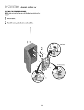
INSTALLATION » STANDARD CONTROL BOX INSTALL THE CONTROL BOARD NOTE: Make sure the battery leads are on the left side of the control box and not pinched. 1 Attach the antenna. 2 Reinstall the batteries, control board, alarm and reset button. 1 2 Coaxial Connector Reset Button Connections Alarm 19
INSTALLATION » STANDARD CONTROL BOX INSTALL THE CONTROL BOARD NOTE: Make sure the battery leads are on the left side of the control box and not pinched. 1 Attach the antenna. 2 Reinstall the batteries, control board, alarm and reset button. 1 2 Coaxial Connector Reset Button Connections Alarm 19
LA400 Manual
Page 21
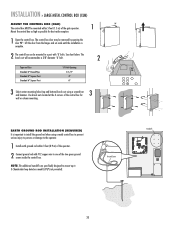
...OPEN LOW BATT TIMER CLOS FORCE GATE 2 ON OFF AUTO OPEN LOW BATT OFF MAX OFF MSIANXGLE BUTTON OFF TIMER TO CLOSE C OPEN SINGLE BUTTON RESET OFF MAX STOP CTRL PWR CTRL PWR SHADOW INTERRUPT CHGR OVLD CTRL PWR AC PWR /SOLAR EARTH GROUND ROD INSTALLATION (REQUIRED) It is 2 The ...BL RD GATE 2 FORCE GATE 2 ON OFF AUTO OPEN LOW BATT OFF MAX SINGLE BUTTON TIMER TO CLOSE OPEN CONTROL INPUTS SINGLE BUTTON OFF MAX RESET STOP CTRL PWR CTRL PWR SHADOW INTERRUPT CHGR OVLD CTRL PWR AC PWR /SOLAR LOOP INPUTS until the installation is important to 3 Chamberlain loop detectors...
...OPEN LOW BATT TIMER CLOS FORCE GATE 2 ON OFF AUTO OPEN LOW BATT OFF MAX OFF MSIANXGLE BUTTON OFF TIMER TO CLOSE C OPEN SINGLE BUTTON RESET OFF MAX STOP CTRL PWR CTRL PWR SHADOW INTERRUPT CHGR OVLD CTRL PWR AC PWR /SOLAR EARTH GROUND ROD INSTALLATION (REQUIRED) It is 2 The ...BL RD GATE 2 FORCE GATE 2 ON OFF AUTO OPEN LOW BATT OFF MAX SINGLE BUTTON TIMER TO CLOSE OPEN CONTROL INPUTS SINGLE BUTTON OFF MAX RESET STOP CTRL PWR CTRL PWR SHADOW INTERRUPT CHGR OVLD CTRL PWR AC PWR /SOLAR LOOP INPUTS until the installation is important to 3 Chamberlain loop detectors...

LA400 Manual
Page 22
... SET CLOSE LIMIT LEARN LIMITS FORCE GATE 2 ON OFF AUTO OPEN LOW BATT OFF MAX SINGLE BUTTON TIMER TO CLOSE OPEN CONTROL INPUTS SINGLE BUTTON RESET OFF MAX STOP CTRL PWR CTRL PWR SHADOW LOOP INPUTS INTERRUPT CHGR OVLD CTRL PWR AC PWR /SOLAR 1 2 120 Vac ONLY The XLM control box...
... SET CLOSE LIMIT LEARN LIMITS FORCE GATE 2 ON OFF AUTO OPEN LOW BATT OFF MAX SINGLE BUTTON TIMER TO CLOSE OPEN CONTROL INPUTS SINGLE BUTTON RESET OFF MAX STOP CTRL PWR CTRL PWR SHADOW LOOP INPUTS INTERRUPT CHGR OVLD CTRL PWR AC PWR /SOLAR 1 2 120 Vac ONLY The XLM control box...
LA400 Manual
Page 31
...position. ADJUSTMENT » LIMITS LIMITS The limits are internal settings that indicate when the gates are in the fully open and close the gate. 30 RESET BUTTON DIAGNOSTIC GATE 1 SET CLOSE 5 When gate is in the desired position, press the LEARN LIMITS button again. LEARN LIMITS button SET OPEN ...LIMIT R2 K2 U4 D4 D2 RESET BUTTON 4 Press the Gate 1 right button to move gate to blink, repeat programming. LIMIT LIMIT 5 When gate is in the desired position, press...
...position. ADJUSTMENT » LIMITS LIMITS The limits are internal settings that indicate when the gates are in the fully open and close the gate. 30 RESET BUTTON DIAGNOSTIC GATE 1 SET CLOSE 5 When gate is in the desired position, press the LEARN LIMITS button again. LEARN LIMITS button SET OPEN ...LIMIT R2 K2 U4 D4 D2 RESET BUTTON 4 Press the Gate 1 right button to move gate to blink, repeat programming. LIMIT LIMIT 5 When gate is in the desired position, press...
LA400 Manual
Page 32
LEARN LIMITS button SET OPEN LIMIT R2 K2 U4 D4 D2 RESET BUTTON 4 Press the GATE 1 right button to open and close the gate. 31 Control board SET SET GATE 2 will blink). SET CLOSE LIMIT LE LIMIT ...GATE 2 FORCE 8 Press the GATE 1 left button to close the right operator. If the problem continues, see Troubleshooting section.) Test the limits by pressing the RESET button. ADJUSTMENT » LIMITS LIMITS NOTES: • The gate with the longer travel span (opening) must be set as the primary gate (GATE 1). • If...
LEARN LIMITS button SET OPEN LIMIT R2 K2 U4 D4 D2 RESET BUTTON 4 Press the GATE 1 right button to open and close the gate. 31 Control board SET SET GATE 2 will blink). SET CLOSE LIMIT LE LIMIT ...GATE 2 FORCE 8 Press the GATE 1 left button to close the right operator. If the problem continues, see Troubleshooting section.) Test the limits by pressing the RESET button. ADJUSTMENT » LIMITS LIMITS NOTES: • The gate with the longer travel span (opening) must be set as the primary gate (GATE 1). • If...

LA400 Manual
Page 33
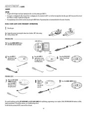
DUAL GATE (RIGHT-SIDE PRIMARY OPERATOR) 1 Close the gate. 2 Engage the operator by pressing the RESET button. Programming times-out automatically after 60 seconds of inactivity. DIAGNOSTIC GATE 1 SET CLOSE 5 Press the GATE 2 left button to move the left operator. PROGRAM ... Troubleshooting section.) Test the limits by pressing the SBC to open the right operator. LEARN LIMITS button SET OPEN LIMIT R2 K2 U4 D4 D2 RESET BUTTON 4 Press the GATE 1 left button to open and close the gate. 32 OPEN LIMIT SET CLOSE LIMIT FORCE SET CLOSE The control board beeps...
DUAL GATE (RIGHT-SIDE PRIMARY OPERATOR) 1 Close the gate. 2 Engage the operator by pressing the RESET button. Programming times-out automatically after 60 seconds of inactivity. DIAGNOSTIC GATE 1 SET CLOSE 5 Press the GATE 2 left button to move the left operator. PROGRAM ... Troubleshooting section.) Test the limits by pressing the SBC to open the right operator. LEARN LIMITS button SET OPEN LIMIT R2 K2 U4 D4 D2 RESET BUTTON 4 Press the GATE 1 left button to open and close the gate. 32 OPEN LIMIT SET CLOSE LIMIT FORCE SET CLOSE The control board beeps...

LA400 Manual
Page 34
... the loops, close edges and close the gate after a specified time period. The TTC is factory set to the desired setting. The force control is reset by a closing gate. • Too much force on contact with an obstruction current sensing feature. ADJUSTMENT » FORCE ADJUSTMENT + TIMER-TO-CLOSE (TTC) Without a properly...
... the loops, close edges and close the gate after a specified time period. The TTC is factory set to the desired setting. The force control is reset by a closing gate. • Too much force on contact with an obstruction current sensing feature. ADJUSTMENT » FORCE ADJUSTMENT + TIMER-TO-CLOSE (TTC) Without a properly...
LA400 Manual
Page 37
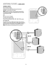
... / STOP / CLOSE / STOP in sequence. Stop (N/C) - These terminals are intended for normal operation (the Stop LED will command the gate to reset the alarms. This input will NOT stop and common input. ADDITIONAL FEATURES » CONTROL INPUTS CONTROL INPUTS WIRE STOP BUTTON (OPTIONAL) A jumper wire ...is installed within line of sight of the gate. Remove only if remotely mounted Stop button is required for use with a single reset button that is factory installed between the stop the gate. NOTE: All Control Inputs must be lit except when the control board goes ...
... / STOP / CLOSE / STOP in sequence. Stop (N/C) - These terminals are intended for normal operation (the Stop LED will command the gate to reset the alarms. This input will NOT stop and common input. ADDITIONAL FEATURES » CONTROL INPUTS CONTROL INPUTS WIRE STOP BUTTON (OPTIONAL) A jumper wire ...is installed within line of sight of the gate. Remove only if remotely mounted Stop button is required for use with a single reset button that is factory installed between the stop the gate. NOTE: All Control Inputs must be lit except when the control board goes ...

LA400 Manual
Page 38
...LOOP COMMON LOOP PRESENCE RELAY 2 LOOP INPUTS C2 FREEQQ SENS MADE IN USA EXIT LOOP NOTE: Additional enclosure required. It will reset the timer to close limit when the shadow loop input is opening gate until the obstruction has been removed. OPEN SAFETY PHOTOELECTRIC ...INPUTS OPEN INPUT AND EXIT LOOP These terminals are intended for use as telephone entry systems, radio receivers (open control. Order part number LA400-BOX to -Close will pause an opening gate for connections. Accessories such as a general open only applications), exit loop detectors, keypads and...
...LOOP COMMON LOOP PRESENCE RELAY 2 LOOP INPUTS C2 FREEQQ SENS MADE IN USA EXIT LOOP NOTE: Additional enclosure required. It will reset the timer to close limit when the shadow loop input is opening gate until the obstruction has been removed. OPEN SAFETY PHOTOELECTRIC ...INPUTS OPEN INPUT AND EXIT LOOP These terminals are intended for use as telephone entry systems, radio receivers (open control. Order part number LA400-BOX to -Close will pause an opening gate for connections. Accessories such as a general open only applications), exit loop detectors, keypads and...

LA400 Manual
Page 39
... MGR20 2-wire electric edge in 5 feet (1.5 m) lengths for 2 inch (5 cm) round post. Do not exceed 500mA with 115 Vac power supply or 300mA with the LA400 to control box depending on wire gauge and distance - 300 mA accessory power, 75 mA switched accessory power. Miller MGR20 2-wire electric edge in 5 feet... K3 D8 Q22 D22 MIN MAX OFF MAX R35 D9 C12 D27 Z3 Z4 U3 C11 OFF MAX F7 C13 C4 F6 F2 SINGLE BUTTON RESET STOP POWER COM COM SHADOW LOOP INPUTS INTERRUPT CHGR OVLD COM F1 20A 32V MOV1 JMPR2 DB1 C64 U2 R9 D1 JMPR1 D4 D2 FUSE...
... MGR20 2-wire electric edge in 5 feet (1.5 m) lengths for 2 inch (5 cm) round post. Do not exceed 500mA with 115 Vac power supply or 300mA with the LA400 to control box depending on wire gauge and distance - 300 mA accessory power, 75 mA switched accessory power. Miller MGR20 2-wire electric edge in 5 feet... K3 D8 Q22 D22 MIN MAX OFF MAX R35 D9 C12 D27 Z3 Z4 U3 C11 OFF MAX F7 C13 C4 F6 F2 SINGLE BUTTON RESET STOP POWER COM COM SHADOW LOOP INPUTS INTERRUPT CHGR OVLD COM F1 20A 32V MOV1 JMPR2 DB1 C64 U2 R9 D1 JMPR1 D4 D2 FUSE...
LA400 Manual
Page 40
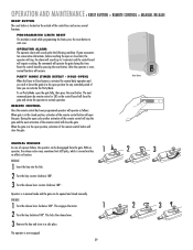
... from the gate. When the gate is in the open position, activation of time you wish to 5 minutes) and the control board will require resetting. RELEASE 1 Insert the key into the lock. 2 Turn the key counter-clockwise 180°. 3 Turn the release lever counter-clockwise 180°.... No commands will resume. After the operator is reset, normal functions will operate the gate during this time. During the open cycle another activation of the remote control will stop , the alarm will ...
... from the gate. When the gate is in the open position, activation of time you wish to 5 minutes) and the control board will require resetting. RELEASE 1 Insert the key into the lock. 2 Turn the key counter-clockwise 180°. 3 Turn the release lever counter-clockwise 180°.... No commands will resume. After the operator is reset, normal functions will operate the gate during this time. During the open cycle another activation of the remote control will stop , the alarm will ...

LA400 Manual
Page 42
... K3 D8 Q22 D22 MIN MAX OFF MAX R35 D9 C12 D27 Z3 Z4 U3 C11 OFF MAX F7 C13 C4 F6 F2 SINGLE BUTTON RESET STOP POWER COM COM SHADOW LOOP INPUTS INTERRUPT CHGR OVLD COM F1 20A 32V MOV1 JMPR2 DB1 C64 U2 R9 D1 JMPR1 D4 D2 FUSE...
... K3 D8 Q22 D22 MIN MAX OFF MAX R35 D9 C12 D27 Z3 Z4 U3 C11 OFF MAX F7 C13 C4 F6 F2 SINGLE BUTTON RESET STOP POWER COM COM SHADOW LOOP INPUTS INTERRUPT CHGR OVLD COM F1 20A 32V MOV1 JMPR2 DB1 C64 U2 R9 D1 JMPR1 D4 D2 FUSE...
LA400 Manual
Page 43
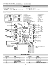
...Arm Disengaged Gate 2 Arm Disengaged Both Gate Arms Disengaged RPM Reversal # OF BLINKS 6 7 8 9 10 42 MEANING Force Reversal Processor Reset ROM Check Failed RAM Check Failed EEPROM Check Failed - WIRING DIAGRAM Solenoid Lock (optional) MAGLOCK NO C NC Maglock (optional) MAGLOCK .... For continued protection against fire and electrocution: • DISCONNECT power and battery BEFORE installing or servicing operator. FORCE SET 24. Reset Limits MASTER OPERATOR ARM CONNECTION 1 ANTENNA CONNECTION 13. LIMIT SET 21. MASTER GATE JOG 20. LOOP INPUTS, SAFETY/SHADOW 9. SECOND...
...Arm Disengaged Gate 2 Arm Disengaged Both Gate Arms Disengaged RPM Reversal # OF BLINKS 6 7 8 9 10 42 MEANING Force Reversal Processor Reset ROM Check Failed RAM Check Failed EEPROM Check Failed - WIRING DIAGRAM Solenoid Lock (optional) MAGLOCK NO C NC Maglock (optional) MAGLOCK .... For continued protection against fire and electrocution: • DISCONNECT power and battery BEFORE installing or servicing operator. FORCE SET 24. Reset Limits MASTER OPERATOR ARM CONNECTION 1 ANTENNA CONNECTION 13. LIMIT SET 21. MASTER GATE JOG 20. LOOP INPUTS, SAFETY/SHADOW 9. SECOND...

LA400 Manual
Page 45
...19446 K74-30941 K001A5747-2 K001A5747 K76-35600 K76-35364 DESCRIPTION QTY Control Board 1 Control Box & Cover with Gasket 1 Control Board Bracket 1 Reset Switch 1 Antenna 1 Battery 2 Transformer 1 Alarm 1 Not Shown ATC Fuse Kit Includes 20 Amp (1), 15 Amp (2) Receiver Module - 390 MHz Receiver Module... - 315 MHz Reset Switch (XLM Control Box) Alarm (XLM Control Box) GATE OPERATOR ARM 22 33 ITEM PART # DESCRIPTION QTY 1 41ASWG-442SA Release Lever 1 2...
...19446 K74-30941 K001A5747-2 K001A5747 K76-35600 K76-35364 DESCRIPTION QTY Control Board 1 Control Box & Cover with Gasket 1 Control Board Bracket 1 Reset Switch 1 Antenna 1 Battery 2 Transformer 1 Alarm 1 Not Shown ATC Fuse Kit Includes 20 Amp (1), 15 Amp (2) Receiver Module - 390 MHz Receiver Module... - 315 MHz Reset Switch (XLM Control Box) Alarm (XLM Control Box) GATE OPERATOR ARM 22 33 ITEM PART # DESCRIPTION QTY 1 41ASWG-442SA Release Lever 1 2...


