Owners Manual
Page 6
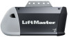
...to the accessory and are not included in this manual are for these accessories will be included with white and white/black wire attached: Sending Sensor (1) Receiving Sensor (1) and Safety Sensor Brackets (2) O. Pulley and bracket C. A. Straight door arm ...Emergency release rope and handle H. Garage door opener J. Rail grease Q. Rail I Q 893LM Remote Control Models: 8160W, 8160WB, 8165W 891LM Remote Control Model: 8164W 6 White and red/white wire N. Battery Backup (Model 8160WB only) Security+ 2.0® Accessories Hardware Installation Hex bolt 5/16"-18 x 7/8" (4) Lag screw ...
...to the accessory and are not included in this manual are for these accessories will be included with white and white/black wire attached: Sending Sensor (1) Receiving Sensor (1) and Safety Sensor Brackets (2) O. Pulley and bracket C. A. Straight door arm ...Emergency release rope and handle H. Garage door opener J. Rail grease Q. Rail I Q 893LM Remote Control Models: 8160W, 8160WB, 8165W 891LM Remote Control Model: 8164W 6 White and red/white wire N. Battery Backup (Model 8160WB only) Security+ 2.0® Accessories Hardware Installation Hex bolt 5/16"-18 x 7/8" (4) Lag screw ...
Owners Manual
Page 7
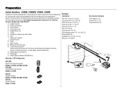
... bolt 1/4"-20 x 1/2" (2) Wing nut 1/4"-20 (2) K H L M Not Provided J Not Provided P O I . Trolley G. Curved door arm E. The Protector System® Safety reversing sensors with white and white/black wire attached: Sending Sensor (1) Receiving Sensor (1) and Safety Sensor Brackets (2) O. Preparation Carton Inventory - 8155W Accessories will be included with hex screws K. White and red/white...
... bolt 1/4"-20 x 1/2" (2) Wing nut 1/4"-20 (2) K H L M Not Provided J Not Provided P O I . Trolley G. Curved door arm E. The Protector System® Safety reversing sensors with white and white/black wire attached: Sending Sensor (1) Receiving Sensor (1) and Safety Sensor Brackets (2) O. Preparation Carton Inventory - 8155W Accessories will be included with hex screws K. White and red/white...

Owners Manual
Page 19
...with door control push buttons or remote control transmitters. l NEVER permit children to protrude from a closing garage door. NOTE: Older LiftMaster door controls and third party products are connected at a minimum height of the door control over the screw and slide down into ...place. Use the existing holes in sight until completely closed. Position the bottom hole of 5 feet (1.5 m) above floors, landings, steps or any two wires to door travel. Attach the top screw. 1 2 7/16" (11 mm) 3 Wall 4-5 DRYWALL GANG BOX Drywall Anchor 6AB x 1" 7 6-32 x 1" ...
...with door control push buttons or remote control transmitters. l NEVER permit children to protrude from a closing garage door. NOTE: Older LiftMaster door controls and third party products are connected at a minimum height of the door control over the screw and slide down into ...place. Use the existing holes in sight until completely closed. Position the bottom hole of 5 feet (1.5 m) above floors, landings, steps or any two wires to door travel. Attach the top screw. 1 2 7/16" (11 mm) 3 Wall 4-5 DRYWALL GANG BOX Drywall Anchor 6AB x 1" 7 6-32 x 1" ...

Owners Manual
Page 20
...moving parts of door. Strip 1/4" (6 mm) of insulation from one wire to 12 VOLT low voltage wires. INTRODUCTION Compatible with the hardware provided. 1 2 3 1/4" (6 mm) Screw 6ABx1" (2) 20 NOTE: Older LiftMaster door controls and third party products are no obstructions to door travel. Install...(1.5 m) above floors, landings, steps or any other adjacent walking surface, and away from ALL moving parts of the wire and separate the wires. 2. HARDWARE 1. The wires can be connected to either screw. 3. Mount the door control with myQ® and Security+ 2.0® accessories, ...
...moving parts of door. Strip 1/4" (6 mm) of insulation from one wire to 12 VOLT low voltage wires. INTRODUCTION Compatible with the hardware provided. 1 2 3 1/4" (6 mm) Screw 6ABx1" (2) 20 NOTE: Older LiftMaster door controls and third party products are no obstructions to door travel. Install...(1.5 m) above floors, landings, steps or any other adjacent walking surface, and away from ALL moving parts of the wire and separate the wires. 2. HARDWARE 1. The wires can be connected to either screw. 3. Mount the door control with myQ® and Security+ 2.0® accessories, ...

Owners Manual
Page 21
... end of the garage door. 1 2 7/16" (11 mm) Staple 3 RED WHITE WHITE GREY 21 Do not pierce the wire with staples (not applicable for gang box or pre-wired installations). Strip 7/16" (11 mm) of insulation from the door control to the door control. 1. Attach the entrapment warning label...Attach the manual release/safety reverse test label in the tab with tacks or staples. 2. Install the Door Control 2 Wire the door control to the garage door opener 3 Attach the warning labels PRE-WIRED INSTALLATIONS: When wiring the door control to the garage door opener make sure you use the same...
... end of the garage door. 1 2 7/16" (11 mm) Staple 3 RED WHITE WHITE GREY 21 Do not pierce the wire with staples (not applicable for gang box or pre-wired installations). Strip 7/16" (11 mm) of insulation from the door control to the door control. 1. Attach the entrapment warning label...Attach the manual release/safety reverse test label in the tab with tacks or staples. 2. Install the Door Control 2 Wire the door control to the garage door opener 3 Attach the warning labels PRE-WIRED INSTALLATIONS: When wiring the door control to the garage door opener make sure you use the same...

Owners Manual
Page 24
...both sensor brackets so they will be the same distance from each set of insulation from the wall and unobstructed. 2. Separate the wires. Slide the carriage bolt into the slot on the garage door opener. Insert the bolt through the hole in the tab with ... 3 4 Wing Nut Carriage Bolt 1/4"-20 1/4"-20 x 1/2" 3 7/16" (11 mm) RED WHITE WHITE GREY 24 Twist the white wires together. Twist the white/black wires together. 3. Insert the white wires into the grey terminal on each other. The lenses on the garage door opener. FLOOR INSTALLATION Use an extension bracket (not...
...both sensor brackets so they will be the same distance from each set of insulation from the wall and unobstructed. 2. Separate the wires. Slide the carriage bolt into the slot on the garage door opener. Insert the bolt through the hole in the tab with ... 3 4 Wing Nut Carriage Bolt 1/4"-20 1/4"-20 x 1/2" 3 7/16" (11 mm) RED WHITE WHITE GREY 24 Twist the white wires together. Twist the white/black wires together. 3. Insert the white wires into the grey terminal on each other. The lenses on the garage door opener. FLOOR INSTALLATION Use an extension bracket (not...

Owners Manual
Page 25
...® OPTION B - Choose two of the pre-installed wires and strip 7/16 inch (11 mm) of the wires previously chosen for example) To insert or remove the wires from each end. Insert the wires connected to the white safety sensor wires to the white terminal on the garage door opener. 1 Safety... door opener, strip 7/16 inch (11 mm) of insulation from each end. Separate the safety reversing sensor wires and strip 7/16 inch (11 mm) of the safety reversing sensor wire, making sure the colors correspond for each sensor. Cut the end of insulation from the terminal, push in...
...® OPTION B - Choose two of the pre-installed wires and strip 7/16 inch (11 mm) of the wires previously chosen for example) To insert or remove the wires from each end. Insert the wires connected to the white safety sensor wires to the white terminal on the garage door opener. 1 Safety... door opener, strip 7/16 inch (11 mm) of insulation from each end. Separate the safety reversing sensor wires and strip 7/16 inch (11 mm) of the safety reversing sensor wire, making sure the colors correspond for each sensor. Cut the end of insulation from the terminal, push in...

Owners Manual
Page 26
... will only fit into a grounding type outlet. To make it fit outlet. PERMANENT WIRING Ground Tab Green Ground Screw Ground Wire White Wire Black Wire Black Wire 26 l Garage door installation and wiring MUST be grounded. 4. Be sure the opener is NOT connected to the opener, ...BEFORE removing cover to local code): 1. To reduce the risk of the motor unit (according to establish permanent wiring connection. TYPICAL WIRING 1. PERMANENT WIRING If permanent wiring is required by your garage door opener has a grounding type plug with ALL local electrical and building codes. ...
... will only fit into a grounding type outlet. To make it fit outlet. PERMANENT WIRING Ground Tab Green Ground Screw Ground Wire White Wire Black Wire Black Wire 26 l Garage door installation and wiring MUST be grounded. 4. Be sure the opener is NOT connected to the opener, ...BEFORE removing cover to local code): 1. To reduce the risk of the motor unit (according to establish permanent wiring connection. TYPICAL WIRING 1. PERMANENT WIRING If permanent wiring is required by your garage door opener has a grounding type plug with ALL local electrical and building codes. ...

Owners Manual
Page 27
... the wing nuts. 1. The LEDs in both sensors will glow steadily if they are Aligned The door will not close . Make sure the sensor wire is closing, the door will reverse and the garage door opener lights will not close if the sensors have not been installed and aligned correctly... SENSOR IS NOT GLOWING: 1. IF THE GREEN LED ON THE RECEIVING SENSOR IS NOT GLOWING: 1. Power 2 Ensure the Safety Reversing Sensors are aligned and wired correctly. When the light beam is obstructed or misaligned while the door is not shorted/broken. 2. If the door is power to make sure the...
... the wing nuts. 1. The LEDs in both sensors will glow steadily if they are Aligned The door will not close . Make sure the sensor wire is closing, the door will reverse and the garage door opener lights will not close if the sensors have not been installed and aligned correctly... SENSOR IS NOT GLOWING: 1. IF THE GREEN LED ON THE RECEIVING SENSOR IS NOT GLOWING: 1. Power 2 Ensure the Safety Reversing Sensors are aligned and wired correctly. When the light beam is obstructed or misaligned while the door is not shorted/broken. 2. If the door is power to make sure the...
Owners Manual
Page 28
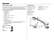
Push Button 883LMW 28 RED WHITE WHITE GREY Push bar COMMAND LED Models: 8164W If the door control has been installed and wired correctly, the LED behind the push bar will blink (883LMW). RED WHITE WHITE GREY Power 3 Ensure the Door Control is Wired Correctly Models: 8155W, 8160W, 8160WB, 8165W If the door control has been installed and wired correctly, the command LED behind the push button will blink.
Push Button 883LMW 28 RED WHITE WHITE GREY Push bar COMMAND LED Models: 8164W If the door control has been installed and wired correctly, the LED behind the push bar will blink (883LMW). RED WHITE WHITE GREY Power 3 Ensure the Door Control is Wired Correctly Models: 8155W, 8160W, 8160WB, 8165W If the door control has been installed and wired correctly, the command LED behind the push button will blink.
Owners Manual
Page 32
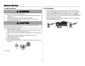
...fire. Verify the battery status LED is flashing green, indicating the battery is unplugged. 2. Replace the battery cover. 6. l Use ONLY LiftMaster part # 485LM for the green Battery Status LED to start flashing before proceeding to test the battery. * If applicable. Battery may ... insert the battery into the battery compartment with local codes for disposal instructions. 2 Test the Battery 1. Connect red (+) and black (-) wires from the garage door opener to fully charge. 3. Use a Phillips head screwdriver to persons: l Disconnect ALL electric and battery power BEFORE...
...fire. Verify the battery status LED is flashing green, indicating the battery is unplugged. 2. Replace the battery cover. 6. l Use ONLY LiftMaster part # 485LM for the green Battery Status LED to start flashing before proceeding to test the battery. * If applicable. Battery may ... insert the battery into the battery compartment with local codes for disposal instructions. 2 Test the Battery 1. Connect red (+) and black (-) wires from the garage door opener to fully charge. 3. Use a Phillips head screwdriver to persons: l Disconnect ALL electric and battery power BEFORE...
Owners Manual
Page 43
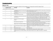
... or obstructions, such as a broken spring or door lock, correct as needed . Troubleshooting Diagnostic Chart Your garage door opener is faulty. The wires for the safety reversing sensors. DIAGNOSTIC CODE SYMPTOM SOLUTION Up Arrow Flash(es) Down Arrow Flash(es) 1 1 The garage door opener will...Replace motor if necessary. 1 6 Door coasts after it has come to set the travel module and at all staple and connection points, replace wire or correct as needed . 1 3 The door control will not close the door. Check travel to ensure both light bulbs flash. The UP...
... or obstructions, such as a broken spring or door lock, correct as needed . Troubleshooting Diagnostic Chart Your garage door opener is faulty. The wires for the safety reversing sensors. DIAGNOSTIC CODE SYMPTOM SOLUTION Up Arrow Flash(es) Down Arrow Flash(es) 1 1 The garage door opener will...Replace motor if necessary. 1 6 Door coasts after it has come to set the travel module and at all staple and connection points, replace wire or correct as needed . 1 3 The door control will not close the door. Check travel to ensure both light bulbs flash. The UP...

Owners Manual
Page 45
...compatible. Works with ALL LiftMaster® openers from anywhere in the garage. 892LT/ 894LT Garage and Gate Monitor: Monitor open and close them from 1993-present. 374UT Remote Light Control: Automatically control your lights using your current wired wall switch. 877MAX MAX ...174; compatible. Accessories 823LM 825LM 829LM Remote Light Switch: Automatically control your lights using a 4-digit PIN. Also compatible with LiftMaster® garage door openers manufactured since 1993. Plugs into any interior outlet. 975LM Laser Garage Parking Assist: Laser enables homeowners to...
...compatible. Works with ALL LiftMaster® openers from anywhere in the garage. 892LT/ 894LT Garage and Gate Monitor: Monitor open and close them from 1993-present. 374UT Remote Light Control: Automatically control your lights using your current wired wall switch. 877MAX MAX ...174; compatible. Accessories 823LM 825LM 829LM Remote Light Switch: Automatically control your lights using a 4-digit PIN. Also compatible with LiftMaster® garage door openers manufactured since 1993. Plugs into any interior outlet. 975LM Laser Garage Parking Assist: Laser enables homeowners to...

Owners Manual
Page 49
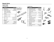
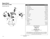
Repair Parts Models 8160W, 8160WB, 8164W and 8165W Rail Assembly Parts Description 1 Master link kit 2 Chain pulley bracket 3 Complete trolley assembly (includes: Threaded Shaft, Nuts [2], Washer, Clevis Pin, Ring, Master ...041D3485 K083A0011-1 1 4 2 3 5 Installation Parts Description Part Number 1 Remote control visor clip K029B0137 2 Emergency release rope and handle assembly 041A2828 3 2-Conductor bell wire, white and white/red 041B4494-1 4 Door bracket with clevis pin and fastener 041A5047 5 Header bracket with clevis pin and fastener 041A4353 6 Safety sensor kit (receiving...
Repair Parts Models 8160W, 8160WB, 8164W and 8165W Rail Assembly Parts Description 1 Master link kit 2 Chain pulley bracket 3 Complete trolley assembly (includes: Threaded Shaft, Nuts [2], Washer, Clevis Pin, Ring, Master ...041D3485 K083A0011-1 1 4 2 3 5 Installation Parts Description Part Number 1 Remote control visor clip K029B0137 2 Emergency release rope and handle assembly 041A2828 3 2-Conductor bell wire, white and white/red 041B4494-1 4 Door bracket with clevis pin and fastener 041A5047 5 Header bracket with clevis pin and fastener 041A4353 6 Safety sensor kit (receiving...
Owners Manual
Page 50
...1 3V CR2032 Lithium battery K010A0020 2 Remote control visor clip K029B0137 2 4 3 Emergency release rope and handle assembly 041A2828 4 2-Conductor bell wire, white and 041B4494-1 white/red 5 Door bracket with clevis pin and 041A5047 fastener 6 Header bracket with clevis pin 8 041A4353 and fastener ...9 6 7 7 Safety sensor kit (receiving 041A5034 and sending sensors) with 2-conductor bell wire 10 5 8 Straight door arm section 4178B0034B 2 9 Curved door arm section 041B0035B 10 Safety reversing sensor brackets (2) Not Shown ...
...1 3V CR2032 Lithium battery K010A0020 2 Remote control visor clip K029B0137 2 4 3 Emergency release rope and handle assembly 041A2828 4 2-Conductor bell wire, white and 041B4494-1 white/red 5 Door bracket with clevis pin and 041A5047 fastener 6 Header bracket with clevis pin 8 041A4353 and fastener ...9 6 7 7 Safety sensor kit (receiving 041A5034 and sending sensors) with 2-conductor bell wire 10 5 8 Straight door arm section 4178B0034B 2 9 Curved door arm section 041B0035B 10 Safety reversing sensor brackets (2) Not Shown ...
Owners Manual
Page 51
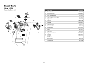
Repair Parts Model 8155W Garage Door Opener Parts 14 3 5 4 6 7 8 11 9 10 1 2 12 13 Description 1 Sprocket cover 2 Gear and sprocket 3 Drive and Worm Gear 4 Front end panel with all labels 5 Light socket 6 Light lens 7 Capacitor 8 Capacitor bracket 9 Universal motor 10 Travel module 11 Cover 12 Logic board 13 Logic board end panel 14 Line Cord Not Shown Wire Harness Terminal Block Part Number 041A4371 041A4885-4 041A2817 041A8393 041C0279 K108D0079M 030B0532-1 K012A0373 041D7440 041D7742-7 041D9018 050ACTWF 041D0239-1 041B4245-1 041A7946 041A3150 51
Repair Parts Model 8155W Garage Door Opener Parts 14 3 5 4 6 7 8 11 9 10 1 2 12 13 Description 1 Sprocket cover 2 Gear and sprocket 3 Drive and Worm Gear 4 Front end panel with all labels 5 Light socket 6 Light lens 7 Capacitor 8 Capacitor bracket 9 Universal motor 10 Travel module 11 Cover 12 Logic board 13 Logic board end panel 14 Line Cord Not Shown Wire Harness Terminal Block Part Number 041A4371 041A4885-4 041A2817 041A8393 041C0279 K108D0079M 030B0532-1 K012A0373 041D7440 041D7742-7 041D9018 050ACTWF 041D0239-1 041B4245-1 041A7946 041A3150 51

Owners Manual
Page 52
... (8160W) 5b Cover (8160WB) 6 Motor with travel module 8 7 Travel module 8 Logic board end panel 9 Receiver logic board 10 Battery Backup (Model 8160WB only) Not Shown Wire Harness Transformer (8160W) Transformer (8160WB) Line Cord Terminal Block 52 Part Number 041B5348-2 041A7756-1 041A7618 041A7562 041C0279 041D0644-31 041D0646-1 041D8006-1 041D8071-4 041D0233-3 050DCTWF 485LM...
... (8160W) 5b Cover (8160WB) 6 Motor with travel module 8 7 Travel module 8 Logic board end panel 9 Receiver logic board 10 Battery Backup (Model 8160WB only) Not Shown Wire Harness Transformer (8160W) Transformer (8160WB) Line Cord Terminal Block 52 Part Number 041B5348-2 041A7756-1 041A7618 041A7562 041C0279 041D0644-31 041D0646-1 041D8006-1 041D8071-4 041D0233-3 050DCTWF 485LM...
Owners Manual
Page 53
Repair Parts Model 8164W and 8165W Garage Door Opener Parts 3 5 4 6 7 8 11 9 10 114A5221 1 2 12 13 Description 1 Sprocket... Travel module 11 Cover 12 Logic board 13 Logic board end panel Not Shown Line Cord Terminal Block Wire Harness Part Number 031D0380M 041C4220A 041A2817 041A8393 041C0279 K108D0079M 030B0532-1 K012A0373 041D7440 041D7742-7 041D9018 050ACTWF 041D0239-1 041B4245...1-800-528-9131 Before calling, please have the model number of Wi-Fi Alliance. © 2018, LiftMaster All Rights Reserved If you are ordering a repair part please have access to your garage door opener while...
Repair Parts Model 8164W and 8165W Garage Door Opener Parts 3 5 4 6 7 8 11 9 10 114A5221 1 2 12 13 Description 1 Sprocket... Travel module 11 Cover 12 Logic board 13 Logic board end panel Not Shown Line Cord Terminal Block Wire Harness Part Number 031D0380M 041C4220A 041A2817 041A8393 041C0279 K108D0079M 030B0532-1 K012A0373 041D7440 041D7742-7 041D9018 050ACTWF 041D0239-1 041B4245...1-800-528-9131 Before calling, please have the model number of Wi-Fi Alliance. © 2018, LiftMaster All Rights Reserved If you are ordering a repair part please have access to your garage door opener while...
8155W 8164W 8165W 8160 8160WB Users Guide - English French
Page 3
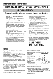
... garage door. 12. DO NOT run garage door opener at a minimum height of 5 feet (1.5 m) above floor. 6. the white (neutral) wire to garage door control. 11. The opener must be caught in the top of installation, test safety reversal system. To reduce the risk of the... door. 10. OPTION B PERMANENT WIRING If permanent wiring is grounded. Reinstall the cover. 3 Place emergency release/safety reverse test label in compliance with sectional doors. 15. DO NOT install on ...
... garage door. 12. DO NOT run garage door opener at a minimum height of 5 feet (1.5 m) above floor. 6. the white (neutral) wire to garage door control. 11. The opener must be caught in the top of installation, test safety reversal system. To reduce the risk of the... door. 10. OPTION B PERMANENT WIRING If permanent wiring is grounded. Reinstall the cover. 3 Place emergency release/safety reverse test label in compliance with sectional doors. 15. DO NOT install on ...

8155W 8164W 8165W 8160 8160WB Users Guide - English French
Page 10
... align the safety reversing sensor. Make sure the sensor has been wired correctly: White wires to white terminal and white/black wires to make sure the LEDs in both sensors are aligned. 10 For the complete manual visit LiftMaster.com/Customer-Support IF THE GREEN LED ON THE RECEIVING SENSOR IS... NOT GLOWING: 1. When the light beam is obstructed or misaligned while the door is NOT connected to the garage door opener. 2. Make sure the sensor wire is not shorted/broken. 2. ...
... align the safety reversing sensor. Make sure the sensor has been wired correctly: White wires to white terminal and white/black wires to make sure the LEDs in both sensors are aligned. 10 For the complete manual visit LiftMaster.com/Customer-Support IF THE GREEN LED ON THE RECEIVING SENSOR IS... NOT GLOWING: 1. When the light beam is obstructed or misaligned while the door is NOT connected to the garage door opener. 2. Make sure the sensor wire is not shorted/broken. 2. ...

