

8165W Product Guide
Page 1
...compatibility and Siri® voice control to 3 openers or MyQ Light Accessories. SECURE SECURITY+ 2.0® SENDS A NEW CODE WITH EVERY REMOTE CLICK. 1/2 8165W H P A C C H A I N D R I V E W I ® GARAGE DOOR OPENER KEY FEATURES Reliable performance. F I -...8482; 10.0 or later or an iPad® with multiple home automation platforms. Visit LiftMaster.com/WorksWithMyQ for a full list of MyQ partners.* RELIABLE 1/2 HP AC MOTOR IS... SMART BUILT-IN WI-FI FOR THE EASIEST WAY TO CONNECT THE GARAGE. Installs easily in the house. REMOTE LIGHT CONTROL Plug in any room in the...
...compatibility and Siri® voice control to 3 openers or MyQ Light Accessories. SECURE SECURITY+ 2.0® SENDS A NEW CODE WITH EVERY REMOTE CLICK. 1/2 8165W H P A C C H A I N D R I V E W I ® GARAGE DOOR OPENER KEY FEATURES Reliable performance. F I -...8482; 10.0 or later or an iPad® with multiple home automation platforms. Visit LiftMaster.com/WorksWithMyQ for a full list of MyQ partners.* RELIABLE 1/2 HP AC MOTOR IS... SMART BUILT-IN WI-FI FOR THE EASIEST WAY TO CONNECT THE GARAGE. Installs easily in the house. REMOTE LIGHT CONTROL Plug in any room in the...
8165W Product Guide
Page 2
...mark of Gentex Corporation LMGDENPG8165W 3/18 SHIPPING. Installed Length Max. B ur gla r y C o ding -- Down Safety Reverse -- MASTERFUL ENGINEERING. P r on a sectional door. © 2018 LiftMaster All Rights Reserved 300 Windsor Drive, Oak Brook, IL 60523 LiftMaster.com ALARM.COM is a registered trademark ...Controls, 1 Keyless Entry System and 16 MyQ Devices †WARNING: to -Close and MyQ remote operation features when opener is installed on g ) 8165W 1/2 HP AC CHAIN DRIVE WI-FI® GARAGE DOOR OPENER MECHANICS --St ee l Chassis, T- Clare Controls is a...
...mark of Gentex Corporation LMGDENPG8165W 3/18 SHIPPING. Installed Length Max. B ur gla r y C o ding -- Down Safety Reverse -- MASTERFUL ENGINEERING. P r on a sectional door. © 2018 LiftMaster All Rights Reserved 300 Windsor Drive, Oak Brook, IL 60523 LiftMaster.com ALARM.COM is a registered trademark ...Controls, 1 Keyless Entry System and 16 MyQ Devices †WARNING: to -Close and MyQ remote operation features when opener is installed on g ) 8165W 1/2 HP AC CHAIN DRIVE WI-FI® GARAGE DOOR OPENER MECHANICS --St ee l Chassis, T- Clare Controls is a...

Owners Manual
Page 1
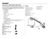
... and features are required to 71403 (US) or visit www.liftmaster.photo (Global) LiftMaster 300 Windsor Drive Oak Brook, IL 60523 Register your garage door... points ( ). Wi-Fi® Garage Door Opener Contractor Series Chain Drive Models 8160W, 8160WB, 8164W, and 8165W Contractor Series Belt Drive Model 8155W FOR RESIDENTIAL USE ONLY • Please read this manual and the safety materials ... compatible with sectional doors. • Attach warning labels to receive updates and offers from LiftMaster Take a photo of the garage door opener are to be used ONLY with myQ® and Security+ 2.0®...
... and features are required to 71403 (US) or visit www.liftmaster.photo (Global) LiftMaster 300 Windsor Drive Oak Brook, IL 60523 Register your garage door... points ( ). Wi-Fi® Garage Door Opener Contractor Series Chain Drive Models 8160W, 8160WB, 8164W, and 8165W Contractor Series Belt Drive Model 8155W FOR RESIDENTIAL USE ONLY • Please read this manual and the safety materials ... compatible with sectional doors. • Attach warning labels to receive updates and offers from LiftMaster Take a photo of the garage door opener are to be used ONLY with myQ® and Security+ 2.0®...
Owners Manual
Page 2
Models 8160W, 8160WB, 8164W, 8165W 6 Carton Inventory - Models 8155W 7 Assembly for Models: 8160W, 8160WB, 8164W, 8165W 8 Assembly for Model: 8155W 9 Installation 10 Install the Door Control 19-21 Install the Door Control - 882LMW 19 Install the Door Control - 883LMW 20 ...Troubleshooting 43-44 Accessories 45 Warranty 46 Automatic Garage Door Opener Safety & Maintenance Guide 47-48 Repair Parts 49-53 Install...
Models 8160W, 8160WB, 8164W, 8165W 6 Carton Inventory - Models 8155W 7 Assembly for Models: 8160W, 8160WB, 8164W, 8165W 8 Assembly for Model: 8155W 9 Installation 10 Install the Door Control 19-21 Install the Door Control - 882LMW 19 Install the Door Control - 883LMW 20 ...Troubleshooting 43-44 Accessories 45 Warranty 46 Automatic Garage Door Opener Safety & Maintenance Guide 47-48 Repair Parts 49-53 Install...

Owners Manual
Page 3
... carefully. The Timer-to-Close (TTC) feature, the myQ Smartphone Control, and any other myQ devices are known to the State of the door is installed, operated, maintained and tested in strict accordance with the instructions and warnings contained in the line of sight of California to cause cancer or birth...
... carefully. The Timer-to-Close (TTC) feature, the myQ Smartphone Control, and any other myQ devices are known to the State of the door is installed, operated, maintained and tested in strict accordance with the instructions and warnings contained in the line of sight of California to cause cancer or birth...

Owners Manual
Page 4
... Wi-Fi enabled smartphone, tablet or laptop l Broadband Internet Connection l Wi-Fi signal in the way of the header bracket, it should be installed above the center of the door. Check the Door To prevent possible SERIOUS INJURY or DEATH: l ALWAYS call a trained door Spring OR Spring ...To prevent damage to the garage door. 2. Disable locks and remove any ropes connected to garage door and opener: l ALWAYS disable locks BEFORE installing and operating the opener. Hold your mobile device in place, supported entirely by its springs. 3. If Torsion Extension your door binds, sticks, or...
... Wi-Fi enabled smartphone, tablet or laptop l Broadband Internet Connection l Wi-Fi signal in the way of the header bracket, it should be installed above the center of the door. Check the Door To prevent possible SERIOUS INJURY or DEATH: l ALWAYS call a trained door Spring OR Spring ...To prevent damage to the garage door. 2. Disable locks and remove any ropes connected to garage door and opener: l ALWAYS disable locks BEFORE installing and operating the opener. Hold your mobile device in place, supported entirely by its springs. 3. If Torsion Extension your door binds, sticks, or...
Owners Manual
Page 6
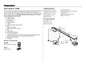
...N. Depending on the garage door opener model purchased. A. Rail I Q 893LM Remote Control Models: 8160W, 8160WB, 8165W 891LM Remote Control Model: 8164W 6 The Protector System® Safety reversing sensors with your garage door opener. Sprocket cover... door arm E. Straight door arm F. Emergency release rope and handle H. Safety labels and literature P. Battery Backup (Model 8160WB only) Security+ 2.0® Accessories Hardware Installation Hex bolt 5/16"-18 x 7/8" (4) Lag screw 5/16"-9 x 1-5/8" (2) Clevis Pin 5/16" x 2-3/4" (1) Clevis Pin 5/16" x 1-1/4" (1) Clevis ...
...N. Depending on the garage door opener model purchased. A. Rail I Q 893LM Remote Control Models: 8160W, 8160WB, 8165W 891LM Remote Control Model: 8164W 6 The Protector System® Safety reversing sensors with your garage door opener. Sprocket cover... door arm E. Straight door arm F. Emergency release rope and handle H. Safety labels and literature P. Battery Backup (Model 8160WB only) Security+ 2.0® Accessories Hardware Installation Hex bolt 5/16"-18 x 7/8" (4) Lag screw 5/16"-9 x 1-5/8" (2) Clevis Pin 5/16" x 2-3/4" (1) Clevis Pin 5/16" x 1-1/4" (1) Clevis ...
Owners Manual
Page 7
... this manual. Straight door arm F. Emergency release rope and handle H. White and red/white wire N. Garage door opener J. Header bracket B. Pulley and bracket C. Rail grease Installation Hardware Hex bolt 5/16"-18 x 7/8" (4) Lag screw 5/16"-9 x 1-5/8" (2) Clevis Pin 5/16" x 2-3/4" (1) Clevis Pin 5/16" x 1-1/4" (1) Clevis Pin 5/16" x 1" (1) Nut 5/16"-18 (4) Door Control Hardware Screw 6AB...
... this manual. Straight door arm F. Emergency release rope and handle H. White and red/white wire N. Garage door opener J. Header bracket B. Pulley and bracket C. Rail grease Installation Hardware Hex bolt 5/16"-18 x 7/8" (4) Lag screw 5/16"-9 x 1-5/8" (2) Clevis Pin 5/16" x 2-3/4" (1) Clevis Pin 5/16" x 1-1/4" (1) Clevis Pin 5/16" x 1" (1) Nut 5/16"-18 (4) Door Control Hardware Screw 6AB...

Owners Manual
Page 8
... Place the garage door opener on the trolley threaded shaft. 2. Remove the two bolts from the top of sprocket while operating opener. b) 8164W and 8165W 8 Re-tighten the inner nut. To avoid SERIOUS damage to prevent scratching. 1. Fasten the rail with hex screws. Position the chain around the garage ...1/2" above the base of the rail at the midpoint of the opener. Slack in the garage door opener) 1/2" (13 mm) 5. b) For models 8164W and 8165W, install the sprocket cover by squeezing the sides and inserting the tabs into the slots on the garage door opener.
... Place the garage door opener on the trolley threaded shaft. 2. Remove the two bolts from the top of sprocket while operating opener. b) 8164W and 8165W 8 Re-tighten the inner nut. To avoid SERIOUS damage to prevent scratching. 1. Fasten the rail with hex screws. Position the chain around the garage ...1/2" above the base of the rail at the midpoint of the opener. Slack in the garage door opener) 1/2" (13 mm) 5. b) For models 8164W and 8165W, install the sprocket cover by squeezing the sides and inserting the tabs into the slots on the garage door opener.
Owners Manual
Page 10
... (1.5 m) above floors, landings, steps or any other hardware MUST be caught in a prominent location. 11. Place entrapment warning label on a one -piece door, visit LiftMaster.com for installation instructions. 10 Place emergency release/safety reverse test label in SEVERE INJURY or DEATH. 3. Door MUST reverse on properly balanced and lubricated garage door...
... (1.5 m) above floors, landings, steps or any other hardware MUST be caught in a prominent location. 11. Place entrapment warning label on a one -piece door, visit LiftMaster.com for installation instructions. 10 Place emergency release/safety reverse test label in SEVERE INJURY or DEATH. 3. Door MUST reverse on properly balanced and lubricated garage door...

Owners Manual
Page 11
...might NOT reverse when required. This height will provide travel as shown. l NEVER try to the highest point of travel clearance for ceiling installation. Open your garage, use lag screws (not provided) to securely fasten the 2x4 to structural supports. Unfinished Ceiling Header Wall ... line on the wall upside down if necessary, to -Close functionality if operating either one-piece or swinging garage doors. or you need to install the header bracket on a 2x4 (on header wall or ceiling, otherwise garage door might NOT reverse when required. l ALWAYS call a trained...
...might NOT reverse when required. This height will provide travel as shown. l NEVER try to the highest point of travel clearance for ceiling installation. Open your garage, use lag screws (not provided) to securely fasten the 2x4 to structural supports. Unfinished Ceiling Header Wall ... line on the wall upside down if necessary, to -Close functionality if operating either one-piece or swinging garage doors. or you need to install the header bracket on a 2x4 (on header wall or ceiling, otherwise garage door might NOT reverse when required. l ALWAYS call a trained...

Owners Manual
Page 12
...than 6" (15 cm) from the wall. Mark the side holes. WALL INSTALLATION 1. Drill 3/16" pilot holes and fasten the bracket securely to a structural support with the hardware provided. Installation 2 Install the Header Bracket You can be mounted flush against the ceiling when clearance is...Screw 5/16"-9 x 1-5/8" (Header Wall) Optional Mounting Holes Highest Point of bracket holes (do not use concrete anchors (not provided). If installing into masonry, use the holes designated for your particular requirements. HARDWARE OPTION B - Make sure the arrow is minimal. 3. Mark the ...
...than 6" (15 cm) from the wall. Mark the side holes. WALL INSTALLATION 1. Drill 3/16" pilot holes and fasten the bracket securely to a structural support with the hardware provided. Installation 2 Install the Header Bracket You can be mounted flush against the ceiling when clearance is...Screw 5/16"-9 x 1-5/8" (Header Wall) Optional Mounting Holes Highest Point of bracket holes (do not use concrete anchors (not provided). If installing into masonry, use the holes designated for your particular requirements. HARDWARE OPTION B - Make sure the arrow is minimal. 3. Mark the ...

Owners Manual
Page 13
... can remain disconnected until instructed. If the door hits the trolley when it is raised, pull the trolley release arm down to the Header Bracket 1. Installation 3 Attach the Rail to disconnect the inner and outer trolley. If the ladder is ideal for the garage door opener. HARDWARE 4 Position the Garage Door...
... can remain disconnected until instructed. If the door hits the trolley when it is raised, pull the trolley release arm down to the Header Bracket 1. Installation 3 Attach the Rail to disconnect the inner and outer trolley. If the ladder is ideal for the garage door opener. HARDWARE 4 Position the Garage Door...
Owners Manual
Page 14
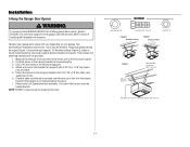
... make sure the rail is not centered above the door). 7. Operate the door manually. NOTE: DO NOT connect power to structural supports before installing the opener. Installation 5 Hang the Garage Door Opener To avoid possible SERIOUS INJURY from each bracket to a support with 5/16"-18 x 7/8" hex bolts, lock...the header bracket if the bracket is centered over the door (or in the structural supports. 4. Yours may be used if installing ANY brackets into masonry. Hanging brackets should be angled (Figure 1) to the hanging brackets with 5/16"-18 x 1-7/8" lag screws (not provided). 5.
... make sure the rail is not centered above the door). 7. Operate the door manually. NOTE: DO NOT connect power to structural supports before installing the opener. Installation 5 Hang the Garage Door Opener To avoid possible SERIOUS INJURY from each bracket to a support with 5/16"-18 x 7/8" hex bolts, lock...the header bracket if the bracket is centered over the door (or in the structural supports. 4. Yours may be used if installing ANY brackets into masonry. Hanging brackets should be angled (Figure 1) to the hanging brackets with 5/16"-18 x 1-7/8" lag screws (not provided). 5.

Owners Manual
Page 15
Rotate the lens up to close the lens. l DO NOT use halogen bulbs. Install a 100 watt maximum light bulb in the fully open position. Then the lights will turn OFF. 3. Pull on both sides of the end panel or ... 100W. The lights will turn ON and remain lit for Models 8155W, 8164W and 8165W To prevent possible OVERHEATING of lens. l DO NOT use incandescent bulbs larger than 26W (100W equivalent). Installation 6 Install the Light Bulbs for Models 8160W, 8160WB Install the Light Bulbs for approximately 4-1/2 minutes when power is in each socket. l DO...
Rotate the lens up to close the lens. l DO NOT use halogen bulbs. Install a 100 watt maximum light bulb in the fully open position. Then the lights will turn OFF. 3. Pull on both sides of the end panel or ... 100W. The lights will turn ON and remain lit for Models 8155W, 8164W and 8165W To prevent possible OVERHEATING of lens. l DO NOT use incandescent bulbs larger than 26W (100W equivalent). Installation 6 Install the Light Bulbs for Models 8160W, 8160WB Install the Light Bulbs for approximately 4-1/2 minutes when power is in each socket. l DO...

Owners Manual
Page 16
... rope through the hole in an open or closed. Insert the other end of the emergency release rope through the handle. Trolley Release Arm 16 Installation 7 Attach the Emergency Release Rope and Handle To prevent possible SERIOUS INJURY or DEATH from the end of the rope to prevent slipping. 2. If rope...
... rope through the hole in an open or closed. Insert the other end of the emergency release rope through the handle. Trolley Release Arm 16 Installation 7 Attach the Emergency Release Rope and Handle To prevent possible SERIOUS INJURY or DEATH from the end of the rope to prevent slipping. 2. If rope...

Owners Manual
Page 17
... Secure the door bracket using the two self threading screws. (Figure 1) l Alternately, use on wood doors. Mark, drill holes and install as follows, depending on the previously marked vertical centerline used for opener reinforcement instructions or reinforcement kit. HARDWARE Self-Threading Screw 1/4"-14 x... 1. A horizontal reinforcement brace should cover the height of door bracket. Contact the garage door manufacturer or installing dealer for the header bracket installation. In this case you will not need the door bracket; Center the door bracket on your door's ...
... Secure the door bracket using the two self threading screws. (Figure 1) l Alternately, use on wood doors. Mark, drill holes and install as follows, depending on the previously marked vertical centerline used for opener reinforcement instructions or reinforcement kit. HARDWARE Self-Threading Screw 1/4"-14 x... 1. A horizontal reinforcement brace should cover the height of door bracket. Contact the garage door manufacturer or installing dealer for the header bracket installation. In this case you will not need the door bracket; Center the door bracket on your door's ...

Owners Manual
Page 18
...) about 2" (5 cm). 2. Attach with the ring fastener. 3. Select two aligned holes (as far apart as possible) and attach using the bolts, nuts and lock washers. Installation 9 Connect the Door Arm to the outer trolley using the clevis pin. Attach with the ring fastener. 4. Pull the emergency release handle toward the garage...
...) about 2" (5 cm). 2. Attach with the ring fastener. 3. Select two aligned holes (as far apart as possible) and attach using the bolts, nuts and lock washers. Installation 9 Connect the Door Arm to the outer trolley using the clevis pin. Attach with the ring fastener. 4. Pull the emergency release handle toward the garage...

Owners Manual
Page 19
... door controls. NOTE: Your product may look different than the illustrations. The wires can be connected to either screw. NOTE: Older LiftMaster door controls and third party products are not compatible. Strip 7/16" (11 mm) of insulation from ALL moving parts of the wire...6-32 x 1" 8 6 DRYWALL Drywall Anchor 6AB x 1" GANG BOX 6-32 x 1" 19 Your garage door opener is not necessary to drill holes or install the drywall anchors. Mark the location of door. l Connect door control ONLY to protrude from the wall. 5. INTRODUCTION Compatible with door control push buttons or...
... door controls. NOTE: Your product may look different than the illustrations. The wires can be connected to either screw. NOTE: Older LiftMaster door controls and third party products are not compatible. Strip 7/16" (11 mm) of insulation from ALL moving parts of the wire...6-32 x 1" 8 6 DRYWALL Drywall Anchor 6AB x 1" GANG BOX 6-32 x 1" 19 Your garage door opener is not necessary to drill holes or install the drywall anchors. Mark the location of door. l Connect door control ONLY to protrude from the wall. 5. INTRODUCTION Compatible with door control push buttons or...

Owners Manual
Page 20
... power is properly adjusted, and there are not compatible. NOTE: Older LiftMaster door controls and third party products are no obstructions to door travel. Use the existing holes in sight until completely closed. Install door control within sight of garage door, out of reach of small ...with the hardware provided. 1 2 3 1/4" (6 mm) Screw 6ABx1" (2) 20 l Connect door control ONLY to cross path of closing garage door: l Install door control within sight of garage door, out of reach of small children at a minimum height of 5 feet (1.5 m) above floors, landings, steps or ...
... power is properly adjusted, and there are not compatible. NOTE: Older LiftMaster door controls and third party products are no obstructions to door travel. Use the existing holes in sight until completely closed. Install door control within sight of garage door, out of reach of small ...with the hardware provided. 1 2 3 1/4" (6 mm) Screw 6ABx1" (2) 20 l Connect door control ONLY to cross path of closing garage door: l Install door control within sight of garage door, out of reach of small children at a minimum height of 5 feet (1.5 m) above floors, landings, steps or ...


