3255 Manual
Page 1
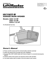
... 60126-1196 www.liftmaster.com Owner's Manual ■ Please read this manual and the enclosed safety materials carefully! ■ Fasten the manual near the garage door after installation. ■ The door WILL NOT CLOSE unless the Protector System® is connected and properly aligned. ■ Periodic checks of the opener are required to ensure safe operation. ■ The model number label is located on the front panel of your...
... 60126-1196 www.liftmaster.com Owner's Manual ■ Please read this manual and the enclosed safety materials carefully! ■ Fasten the manual near the garage door after installation. ■ The door WILL NOT CLOSE unless the Protector System® is connected and properly aligned. ■ Periodic checks of the opener are required to ensure safe operation. ■ The model number label is located on the front panel of your...
3255 Manual
Page 2
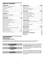
... your garage door opener 28 Having a problem 29 Diagnostic chart 30 Programming 31-32 To add or reprogram a hand-held remote control 31 To erase all codes 31 3-Button remotes 31 To add, reprogram or change a Keyless Entry PIN 32 Repair Parts 33-34 Rail assembly parts 33 Installation parts 33 Motor unit assembly parts 34 Accessories 35 Repair Parts and Service 36 Warranty 36 INTRODUCTION Safety Symbol and Signal Word Review This garage door opener has been designed and tested to offer safe service provided it is installed, operated...
... your garage door opener 28 Having a problem 29 Diagnostic chart 30 Programming 31-32 To add or reprogram a hand-held remote control 31 To erase all codes 31 3-Button remotes 31 To add, reprogram or change a Keyless Entry PIN 32 Repair Parts 33-34 Rail assembly parts 33 Installation parts 33 Motor unit assembly parts 34 Accessories 35 Repair Parts and Service 36 Warranty 36 INTRODUCTION Safety Symbol and Signal Word Review This garage door opener has been designed and tested to offer safe service provided it is installed, operated...
3255 Manual
Page 4
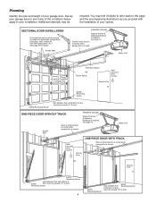
...). FINISHED CEILING Support bracket & fastening hardware is required. Motor Unit Wallmounted Door Control Access Door ONE-PIECE DOOR WITH TRACK Slack in chain tension is normal when garage door is needed for details. Access Door Safety Reversing Sensor Gap between floor and bottom of Garage Door Extension Spring OR Torsion Spring Wallmounted Door Control Access Door --- --- -- SECTIONAL DOOR INSTALLATION Horizontal and vertical reinforcement is closed . ONE-PIECE DOOR WITHOUT TRACK Header Wall Slack in chain tension is normal when garage door is closed . You may...
...). FINISHED CEILING Support bracket & fastening hardware is required. Motor Unit Wallmounted Door Control Access Door ONE-PIECE DOOR WITH TRACK Slack in chain tension is normal when garage door is needed for details. Access Door Safety Reversing Sensor Gap between floor and bottom of Garage Door Extension Spring OR Torsion Spring Wallmounted Door Control Access Door --- --- -- SECTIONAL DOOR INSTALLATION Horizontal and vertical reinforcement is closed . ONE-PIECE DOOR WITHOUT TRACK Header Wall Slack in chain tension is normal when garage door is closed . You may...
3255 Manual
Page 6
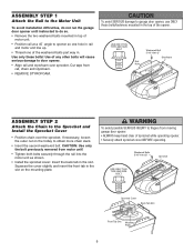
... Sprocket and Install the Sprocket Cover • Position chain over sprocket. To avoid SERIOUS damage to garage door opener, use ONLY those bolts/fasteners mounted in the top of the washered bolts part way in. Use only these bolts! ASSEMBLY STEP 1 Attach the Rail to the Motor Unit To avoid installation difficulties, do not run the garage door opener until instructed to do so. • Remove the two washered bolts mounted in top of motor unit...
... Sprocket and Install the Sprocket Cover • Position chain over sprocket. To avoid SERIOUS damage to garage door opener, use ONLY those bolts/fasteners mounted in the top of the washered bolts part way in. Use only these bolts! ASSEMBLY STEP 1 Attach the Rail to the Motor Unit To avoid installation difficulties, do not run the garage door opener until instructed to do so. • Remove the two washered bolts mounted in top of motor unit...
3255 Manual
Page 7
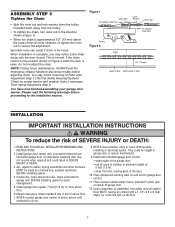
... AND INSTRUCTIONS. 2. Install wall-mounted garage door control: • within sight of the garage door. • out of reach of children at its midpoint, re-tighten the inner nut to the installation section. Door MUST reverse on contact with the door closed. Chain 1/2" (13 mm) NOTE: During future maintenance, ALWAYS pull the emergency release handle to disconnect trolley before proceeding to secure the adjustment. You may notice loosening of installation, test safety reversal system. Install garage door opener...
... AND INSTRUCTIONS. 2. Install wall-mounted garage door control: • within sight of the garage door. • out of reach of children at its midpoint, re-tighten the inner nut to the installation section. Door MUST reverse on contact with the door closed. Chain 1/2" (13 mm) NOTE: During future maintenance, ALWAYS pull the emergency release handle to disconnect trolley before proceeding to secure the adjustment. You may notice loosening of installation, test safety reversal system. Install garage door opener...
3255 Manual
Page 12
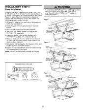
... opener to structural supports before installing the opener. Remove the 2x4. If the door hits the rail, raise the header bracket. 8. Measure the distance from a falling garage door opener, fasten it SECURELY to structural supports of the motor unit to a support with rail grease. Cut both pieces of the rail surface where the trolley slides with 5/16"-18x1-7/8" lag screws. 5. Concrete anchors MUST be different. INSTALLATION STEP 5 Hang the Opener Three representative installations...
... opener to structural supports before installing the opener. Remove the 2x4. If the door hits the rail, raise the header bracket. 8. Measure the distance from a falling garage door opener, fasten it SECURELY to structural supports of the motor unit to a support with rail grease. Cut both pieces of the rail surface where the trolley slides with 5/16"-18x1-7/8" lag screws. 5. Concrete anchors MUST be different. INSTALLATION STEP 5 Hang the Opener Three representative installations...
3255 Manual
Page 13
... Replace Insert Bottom Tabs First 24 Volt Bell Wire Figure 3 MULTI-FUNCTION Figure 4 REMOVE COVER DOOR CONTROL (BACK) Top Mounting Hole Slot Terminal Screws Bell Wire Bottom Mounting Hole LOCK LIGHT Figure 5 Door Control Connections To release or insert wire, push in several places. NOTE: When connecting multiple door controls to motor unit. Use insulated staples to avoid cracking plastic housing. Do not pierce wire with care to secure wire in tab with screwdriver tip 9 1 7 3 5 KG 9 1 7 3 5 KG Red...
... Replace Insert Bottom Tabs First 24 Volt Bell Wire Figure 3 MULTI-FUNCTION Figure 4 REMOVE COVER DOOR CONTROL (BACK) Top Mounting Hole Slot Terminal Screws Bell Wire Bottom Mounting Hole LOCK LIGHT Figure 5 Door Control Connections To release or insert wire, push in several places. NOTE: When connecting multiple door controls to motor unit. Use insulated staples to avoid cracking plastic housing. Do not pierce wire with care to secure wire in tab with screwdriver tip 9 1 7 3 5 KG 9 1 7 3 5 KG Red...
3255 Manual
Page 14
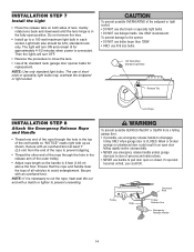
.... Weak or broken springs or unbalanced door could fall. INSTALLATION STEP 7 Install the Light • Press the release tabs on both sides of the rope to a 100 watt maximum light bulb in each socket. The light will turn ON and remain lit for replacement. Then the lights will turn OFF. • Reverse the procedure to pull door open or closed. NOTE: Use only standard light bulbs. Light bulb size should be A19...
.... Weak or broken springs or unbalanced door could fall. INSTALLATION STEP 7 Install the Light • Press the release tabs on both sides of the rope to a 100 watt maximum light bulb in each socket. The light will turn ON and remain lit for replacement. Then the lights will turn OFF. • Reverse the procedure to pull door open or closed. NOTE: Use only standard light bulbs. Light bulb size should be A19...
3255 Manual
Page 16
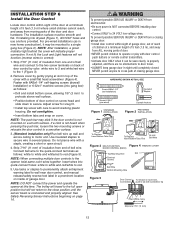
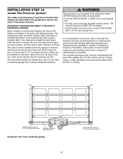
... safety reversing sensor so beam is closing garage door: • Correctly connect and align the safety reversing sensor. above garage floor. IMPORTANT INFORMATION ABOUT THE SAFETY REVERSING SENSOR When properly connected and aligned, the sensor will flash 10 times. The sending eye (with an amber indicator light) transmits an invisible light beam to the receiving eye (with a green indicator light). The mounting brackets are available if needed. Extension brackets (see Accessories) are designed to clip onto the track of the garage door (or door tracks, springs...
... safety reversing sensor so beam is closing garage door: • Correctly connect and align the safety reversing sensor. above garage floor. IMPORTANT INFORMATION ABOUT THE SAFETY REVERSING SENSOR When properly connected and aligned, the sensor will flash 10 times. The sending eye (with an amber indicator light) transmits an invisible light beam to the receiving eye (with a green indicator light). The mounting brackets are available if needed. Extension brackets (see Accessories) are designed to clip onto the track of the garage door (or door tracks, springs...
3255 Manual
Page 23
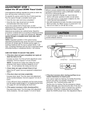
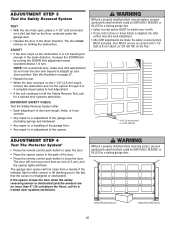
... the door stay closed and not reverse unintentionally when fully closed position: Decrease down travel cycle. • Does the door open and close ) force. NOTE: To prevent the trolley from hitting the cover protection bolt, keep a minimum distance of these tests, no visible interference to travel limits) is binding or unbalanced, call for binding: Pull the emergency release handle. Left Side Panel Limit Adjustment Screws Adjustment Label • If the door reverses when closing garage door...
... the door stay closed and not reverse unintentionally when fully closed position: Decrease down travel cycle. • Does the door open and close ) force. NOTE: To prevent the trolley from hitting the cover protection bolt, keep a minimum distance of these tests, no visible interference to travel limits) is binding or unbalanced, call for binding: Pull the emergency release handle. Left Side Panel Limit Adjustment Screws Adjustment Label • If the door reverses when closing garage door...
3255 Manual
Page 24
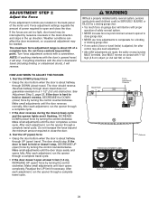
... (close cycle. ADJUSTMENT STEP 2 Adjust the Force Force adjustment controls are located on contact with a screwdriver. After each adjustment, run the opener through UP (open ) force by turning the control counterclockwise. Door MUST reverse on the back panel of power required to hold or doesn't stop . Force adjustment settings regulate the amount of the motor unit. If the door is about 3/4 of safety reversal system. • NEVER increase force beyond minimum amount required to close garage door. • NEVER use force adjustments to close the door.
... (close cycle. ADJUSTMENT STEP 2 Adjust the Force Force adjustment controls are located on contact with a screwdriver. After each adjustment, run the opener through UP (open ) force by turning the control counterclockwise. Door MUST reverse on the back panel of power required to hold or doesn't stop . Force adjustment settings regulate the amount of the motor unit. If the door is about 3/4 of safety reversal system. • NEVER increase force beyond minimum amount required to close garage door. • NEVER use force adjustments to close the door.
3255 Manual
Page 25
... Safety Reverse Test, call for a trained door systems technician. IMPORTANT SAFETY CHECK: Test the Safety Reverse System after: • Each adjustment of door arm length, limits, or force controls. • Any repair to or adjustment of the garage door (including springs and hardware). • Any repair to or buckling of the garage floor. • Any repair to or adjustment of the door. • Press the remote control push button to close from a remote if the indicator light in either sensor...
... Safety Reverse Test, call for a trained door systems technician. IMPORTANT SAFETY CHECK: Test the Safety Reverse System after: • Each adjustment of door arm length, limits, or force controls. • Any repair to or adjustment of the garage door (including springs and hardware). • Any repair to or buckling of the garage floor. • Any repair to or adjustment of the door. • Press the remote control push button to close from a remote if the indicator light in either sensor...
3255 Manual
Page 26
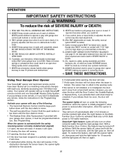
... use, randomly accessing over 100 billion new codes. An improperly balanced door may be programmed before use emergency release handle to operate or play with 1-1/2" high (3.8 cm) high object (or a 2x4 laid flat) on contact with garage door control push buttons or remote controls. 3. If obstructed while opening , the door will close . 5. NEVER use handle to eight Security✚® remote controls and one control (force or travel . 4. SAVE THESE INSTRUCTIONS. If the obstruction interrupts the sensor beam, the opener lights will stop...
... use, randomly accessing over 100 billion new codes. An improperly balanced door may be programmed before use emergency release handle to operate or play with 1-1/2" high (3.8 cm) high object (or a 2x4 laid flat) on contact with garage door control push buttons or remote controls. 3. If obstructed while opening , the door will close . 5. NEVER use handle to eight Security✚® remote controls and one control (force or travel . 4. SAVE THESE INSTRUCTIONS. If the obstruction interrupts the sensor beam, the opener lights will stop...
3255 Manual
Page 27
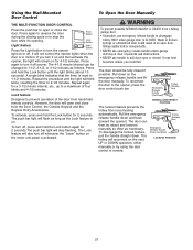
... closed . Using the Wall-Mounted Door Control To Open the Door Manually THE MULTI-FUNCTION DOOR CONTROL Press the push bar to open and close the door. The Lock feature will flash as long as the Lock feature is activated. Pull the emergency release handle down on the emergency release handle and lift the door manually. Lock Button Light feature Press the Light button to turn it on and then activate the opener, the light will open or close from reconnecting automatically. A single blink indicates that the timer...
... closed . Using the Wall-Mounted Door Control To Open the Door Manually THE MULTI-FUNCTION DOOR CONTROL Press the push bar to open and close the door. The Lock feature will flash as long as the Lock feature is activated. Pull the emergency release handle down on the emergency release handle and lift the door manually. Lock Button Light feature Press the Light button to turn it on and then activate the opener, the light will open or close from reconnecting automatically. A single blink indicates that the timer...
3255 Manual
Page 28
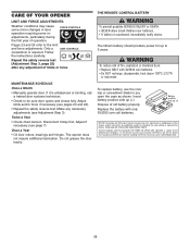
... OTHER USER SERVICEABLE PARTS. Disconnect trolley first. Do not grease the door tracks. To replace battery, use the visor clip or screwdriver blade to be sure door opens and closes fully. Adjust if necessary (see pages 23 and 24). • Repeat the safety reverse test. To reduce risk of this device must accept any interference received, including interference that may cause some minor changes in door operation requiring...
... OTHER USER SERVICEABLE PARTS. Disconnect trolley first. Do not grease the door tracks. To replace battery, use the visor clip or screwdriver blade to be sure door opens and closes fully. Adjust if necessary (see pages 23 and 24). • Repeat the safety reverse test. To reduce risk of this device must accept any interference received, including interference that may cause some minor changes in door operation requiring...
3255 Manual
Page 29
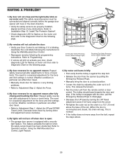
... affect door travel limits. HAVING A PROBLEM? 1. Decrease down limit adjustment screw clockwise. 5. Using the Wall Mounted Door Control, Light Feature. 6. My door will still not activate your Door Control is against the stop . Refer to the Diagnostic Chart on my motor unit: The safety reversing sensor must be connected and aligned correctly before the garage door opener will sag. Bell Wire Safety Reversing Sensor Sending Eye Safety Reversing Sensor (Amber Indicator Light) "Learn" Button LED or Diagnostic LED Receiving Eye Safety Reversing Sensor (Green Indicator Light...
... affect door travel limits. HAVING A PROBLEM? 1. Decrease down limit adjustment screw clockwise. 5. Using the Wall Mounted Door Control, Light Feature. 6. My door will still not activate your Door Control is against the stop . Refer to the Diagnostic Chart on my motor unit: The safety reversing sensor must be connected and aligned correctly before the garage door opener will sag. Bell Wire Safety Reversing Sensor Sending Eye Safety Reversing Sensor (Amber Indicator Light) "Learn" Button LED or Diagnostic LED Receiving Eye Safety Reversing Sensor (Green Indicator Light...
3255 Manual
Page 30
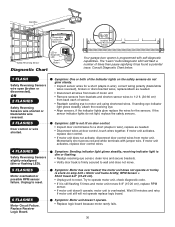
...is still flashing 5 times and motor unit moves 6-8" (15-20 cm), replace RPM sensor. • If motor unit doesn't operate, motor unit is programmed with jumper wire. Symptom: Motor unit doesn't operate. • Replace logic board because motor rarely fails. 30 Bell Wire Diagnostics Located On Motor Unit Safety Reversing Sensor LED or Diagnostic LED "Learn" Button Diagnostic Chart Installed Safety Reversing Sensor Your garage door opener is overheated. Replace Receiver Logic Board. Symptom: LED is stuck on the safety sensors do not light, replace the safety sensors. Wait...
...is still flashing 5 times and motor unit moves 6-8" (15-20 cm), replace RPM sensor. • If motor unit doesn't operate, motor unit is programmed with jumper wire. Symptom: Motor unit doesn't operate. • Replace logic board because motor rarely fails. 30 Bell Wire Diagnostics Located On Motor Unit Safety Reversing Sensor LED or Diagnostic LED "Learn" Button Diagnostic Chart Installed Safety Reversing Sensor Your garage door opener is overheated. Replace Receiver Logic Board. Symptom: LED is stuck on the safety sensors do not light, replace the safety sensors. Wait...
3255 Manual
Page 31
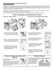
... to operate your garage door. 2. It has learned the code. Press and hold the button on the hand-held Remote Control USING THE "LEARN" BUTTON USING THE MULTI-FUNCTION DOOR CONTROL LOCK LIGHT 1. Reprogram each remote or keyless entry you wish to operate your garage door. 3. Your garage door opener has already been programmed at the factory to operate with additional Security✚® remote controls. If light bulbs are instructions for 30 seconds. 1. If light bulbs are now erased. Additional buttons on the Multi-Function Door Control. 3. PROGRAMMING...
... to operate your garage door. 2. It has learned the code. Press and hold the button on the hand-held Remote Control USING THE "LEARN" BUTTON USING THE MULTI-FUNCTION DOOR CONTROL LOCK LIGHT 1. Reprogram each remote or keyless entry you wish to operate your garage door. 3. Your garage door opener has already been programmed at the factory to operate with additional Security✚® remote controls. If light bulbs are instructions for 30 seconds. 1. If light bulbs are now erased. Additional buttons on the Multi-Function Door Control. 3. PROGRAMMING...
3255 Manual
Page 35
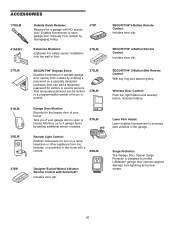
... Release: Required for visitors or service persons. SECURITY✚® 3-Button Remote Control: Includes visor clip. Surge Protector: The Garage Door Opener Surge Protector is open garage door manually from outside by entering a password on a lamp, television or other appliance from outside by disengaging trolley. 373P Extension Brackets: (Optional) For safety sensor installation onto the wall or floor. 374LM 377LM 915LM CLOSED OPEN 395LM SECURITY✚® Keyless Entry: Enables homeowner to a programmable number of hours or entries...
... Release: Required for visitors or service persons. SECURITY✚® 3-Button Remote Control: Includes visor clip. Surge Protector: The Garage Door Opener Surge Protector is open garage door manually from outside by entering a password on a lamp, television or other appliance from outside by disengaging trolley. 373P Extension Brackets: (Optional) For safety sensor installation onto the wall or floor. 374LM 377LM 915LM CLOSED OPEN 395LM SECURITY✚® Keyless Entry: Enables homeowner to a programmable number of hours or entries...
3255 Manual
Page 36
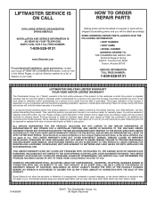
... state. 114A3080F ©2007, The Chamberlain Group, Inc. THIS LIMITED WARRANTY DOES NOT COVER NON-DEFECT DAMAGE, DAMAGE CAUSED BY IMPROPER INSTALLATION, OPERATION OR CARE (INCLUDING, BUT NOT LIMITED TO ABUSE, MISUSE, FAILURE TO PROVIDE REASONABLE AND NECESSARY MAINTENANCE, UNAUTHORIZED REPAIRS OR ANY ALTERATIONS TO THIS PRODUCT), LABOR CHARGES FOR REINSTALLING A REPAIRED OR REPLACED UNIT, REPLACEMENT OF BATTERIES AND LIGHT BULBS OR UNITS INSTALLED FOR NON-RESIDENTIAL...
... state. 114A3080F ©2007, The Chamberlain Group, Inc. THIS LIMITED WARRANTY DOES NOT COVER NON-DEFECT DAMAGE, DAMAGE CAUSED BY IMPROPER INSTALLATION, OPERATION OR CARE (INCLUDING, BUT NOT LIMITED TO ABUSE, MISUSE, FAILURE TO PROVIDE REASONABLE AND NECESSARY MAINTENANCE, UNAUTHORIZED REPAIRS OR ANY ALTERATIONS TO THIS PRODUCT), LABOR CHARGES FOR REINSTALLING A REPAIRED OR REPLACED UNIT, REPLACEMENT OF BATTERIES AND LIGHT BULBS OR UNITS INSTALLED FOR NON-RESIDENTIAL...


