
3255 Manual
Page 2
... and signal word review 2 Preparing your garage door 3 Tools needed 3 Planning 4 Carton inventory 5 Hardware inventory 5 Assembly 6-7 Attach the rail to the motor unit 6 Attach the chain to the sprocket 6 Tighten the chain 7 Installation 7-22 Installation safety instructions 7 Determine the header... bracket location 8 Install the header bracket 9 Attach the rail to the header bracket 10 Position the opener 11 Hang the opener 12 Install the door control 13 Install the light...
... and signal word review 2 Preparing your garage door 3 Tools needed 3 Planning 4 Carton inventory 5 Hardware inventory 5 Assembly 6-7 Attach the rail to the motor unit 6 Attach the chain to the sprocket 6 Tighten the chain 7 Installation 7-22 Installation safety instructions 7 Determine the header... bracket location 8 Install the header bracket 9 Attach the rail to the header bracket 10 Position the opener 11 Hang the opener 12 Install the door control 13 Install the light...
3255 Manual
Page 5
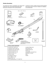
... on the model purchased. is also listed below . contain the motor unit and all parts illustrated below . 3245 (1), 3255 (1), 3255-2 (2) LOCK LIGHT Multi-Function Door Control Panel : SECURITY ® Single-Button Remote Control Remote Control Visor Clip Chain ... Washer 5/16" (4) Screw 6ABx1-1/4" (2) Screw 6-32x1" (2) Self-Threading Screw 1/4"-14x5/8" (2) Insulated Staples (30) Ring Fastener (3) Drywall Anchors (2) Rail Grease Carriage Bolt 1/4"-20x1/2" (2) Wing Nut 1/4"-20 (2) Rope Handle 5 Straight Door Arm Section Carton Inventory Your garage door opener is packaged in the foam...
... on the model purchased. is also listed below . contain the motor unit and all parts illustrated below . 3245 (1), 3255 (1), 3255-2 (2) LOCK LIGHT Multi-Function Door Control Panel : SECURITY ® Single-Button Remote Control Remote Control Visor Clip Chain ... Washer 5/16" (4) Screw 6ABx1-1/4" (2) Screw 6-32x1" (2) Self-Threading Screw 1/4"-14x5/8" (2) Insulated Staples (30) Ring Fastener (3) Drywall Anchors (2) Rail Grease Carriage Bolt 1/4"-20x1/2" (2) Wing Nut 1/4"-20 (2) Rope Handle 5 Straight Door Arm Section Carton Inventory Your garage door opener is packaged in the foam...
3255 Manual
Page 6
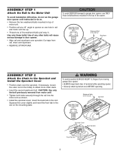
... to garage door opener, use ONLY those bolts/fasteners mounted in the top of the opener. CAUTION: Use only the bolt previously removed from rail, chain and styrofoam. • REMOVE STYROFOAM. Washered Bolts 5/16"-18x1/2" Sprocket USE ONLY THIS TYPE AND SIZE BOLT Sprocket Cover Back Tab...8226; Position chain over sprocket. If necessary, loosen the outer nut on the mounting plate. Use only these bolts! ASSEMBLY STEP 1 Attach the Rail to the Motor Unit To avoid installation difficulties, do not run the garage door opener until instructed to do so. • Remove the two...
... to garage door opener, use ONLY those bolts/fasteners mounted in the top of the opener. CAUTION: Use only the bolt previously removed from rail, chain and styrofoam. • REMOVE STYROFOAM. Washered Bolts 5/16"-18x1/2" Sprocket USE ONLY THIS TYPE AND SIZE BOLT Sprocket Cover Back Tab...8226; Position chain over sprocket. If necessary, loosen the outer nut on the mounting plate. Use only these bolts! ASSEMBLY STEP 1 Attach the Rail to the Motor Unit To avoid installation difficulties, do not run the garage door opener until instructed to do so. • Remove the two...
3255 Manual
Page 7
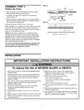
... SEVERE INJURY or DEATH. 3. Please read the following warnings before proceeding to disconnect trolley before adjusting chain. Upon completion of Rail You have now finished assembling your garage door opener. Trolley Figure 2 Sprocket noise can result if chain is complete, you may... garage door opener only on wall next to avoid entanglement. 5. Mount emergency release handle 6 feet (1.83 m) above floor. 6. Base of Rail Mid Length of installation, test safety reversal system. An improperly balanced door may notice loosening of chain after Adjustment Step 3 (Test the Safety...
... SEVERE INJURY or DEATH. 3. Please read the following warnings before proceeding to disconnect trolley before adjusting chain. Upon completion of Rail You have now finished assembling your garage door opener. Trolley Figure 2 Sprocket noise can result if chain is complete, you may... garage door opener only on wall next to avoid entanglement. 5. Mount emergency release handle 6 feet (1.83 m) above floor. 6. Base of Rail Mid Length of installation, test safety reversal system. An improperly balanced door may notice loosening of chain after Adjustment Step 3 (Test the Safety...
3255 Manual
Page 10
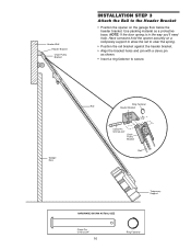
...as shown. • Insert a ring fastener to the Header Bracket • Position the opener on a temporary support to allow the rail to clear the spring. • Position the rail bracket against the header bracket. • Align the bracket holes and join with a clevis pin as a protective base. NOTE: ...If the door spring is in the way you'll need help. Garage Door Ring Fastener Rail Header Bracket Clevis Pin 5/16"x2-3/4" Chain Pulley Bracket Rail Temporary Support HARDWARE SHOWN ACTUAL SIZE Clevis Pin 5/16"x2-3/4" 10 Ring Fastener
...as shown. • Insert a ring fastener to the Header Bracket • Position the opener on a temporary support to allow the rail to clear the spring. • Position the rail bracket against the header bracket. • Align the bracket holes and join with a clevis pin as a protective base. NOTE: ...If the door spring is in the way you'll need help. Garage Door Ring Fastener Rail Header Bracket Clevis Pin 5/16"x2-3/4" Chain Pulley Bracket Rail Temporary Support HARDWARE SHOWN ACTUAL SIZE Clevis Pin 5/16"x2-3/4" 10 Ring Fastener
3255 Manual
Page 11
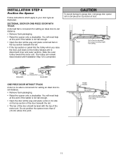
... level with the top of the motor unit. ENGAGED Trolley Release Arm RELEASED ONE-PIECE DOOR WITHOUT TRACK A 2x4 on the trolley release arm to -rail distance. • Remove foam packaging. • Raise the opener onto a stepladder. INSTALLATION STEP 4 Position the Opener Follow instructions which apply to determine the correct mounting...if the ladder is not tall enough. • Open the door all the way and place a 2x4 laid flat on the top section beneath the rail. • If the top section or panel hits the trolley when you raise the door, pull down on its side on top section of Door...
... level with the top of the motor unit. ENGAGED Trolley Release Arm RELEASED ONE-PIECE DOOR WITHOUT TRACK A 2x4 on the trolley release arm to -rail distance. • Remove foam packaging. • Raise the opener onto a stepladder. INSTALLATION STEP 4 Position the Opener Follow instructions which apply to determine the correct mounting...if the ladder is not tall enough. • Open the door all the way and place a 2x4 laid flat on the top section beneath the rail. • If the top section or panel hits the trolley when you raise the door, pull down on its side on top section of Door...
3255 Manual
Page 12
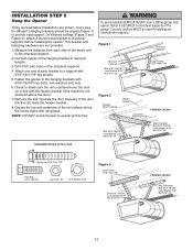
...3), attach a sturdy metal bracket to required lengths. 3. This bracket and fastening hardware are shown. Attach one end of each side of the rail surface where the trolley slides with the header bracket if the bracket is centered over the door (or in the structural supports. 4. Fasten the ... the distance from a falling garage door opener, fasten it SECURELY to opener at this time. Drill 3/16" pilot holes in line with rail grease. NOTE: DO NOT connect power to structural supports of the hanging bracket to structural supports before installing the opener. INSTALLATION STEP 5 Hang...
...3), attach a sturdy metal bracket to required lengths. 3. This bracket and fastening hardware are shown. Attach one end of each side of the rail surface where the trolley slides with the header bracket if the bracket is centered over the door (or in the structural supports. 4. Fasten the ... the distance from a falling garage door opener, fasten it SECURELY to opener at this time. Drill 3/16" pilot holes in line with rail grease. NOTE: DO NOT connect power to structural supports of the hanging bracket to structural supports before installing the opener. INSTALLATION STEP 5 Hang...
3255 Manual
Page 29
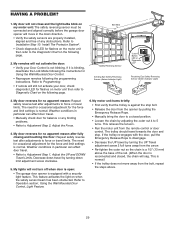
... on the following the programming instructions. Weather conditions in the down direction. • Verify the safety sensors are properly installed, aligned and free of the rail. (When the door is against the stop . This relieves the tension. • Run the motor unit from the opener by pulling the Emergency Release Rope...
... on the following the programming instructions. Weather conditions in the down direction. • Verify the safety sensors are properly installed, aligned and free of the rail. (When the door is against the stop . This relieves the tension. • Run the motor unit from the opener by pulling the Emergency Release Rope...
3255 Manual
Page 33
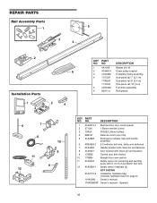
... Owner's manual - NO. NO. Spanish 33 DESCRIPTION 1 4A1008 Master link kit 6 2 41A4813 Chain pulley bracket 3 41A3489 Complete trolley assembly 4 1707LM One-piece rail 7' (2.1 m) 1708LM One-piece rail 8' (2.4 m) 1710LM One-piece rail 10' (3 m) 5 41D3484 Full chain assembly 6 83A11-2 Rail grease 1 LOCK LIGHT 3 2 4 5 7 CEILING MOUNT ONLY UP NOTICE 6 10 11 12 8 9 KEY PART NO. REPAIR PARTS...
... Owner's manual - NO. NO. Spanish 33 DESCRIPTION 1 4A1008 Master link kit 6 2 41A4813 Chain pulley bracket 3 41A3489 Complete trolley assembly 4 1707LM One-piece rail 7' (2.1 m) 1708LM One-piece rail 8' (2.4 m) 1710LM One-piece rail 10' (3 m) 5 41D3484 Full chain assembly 6 83A11-2 Rail grease 1 LOCK LIGHT 3 2 4 5 7 CEILING MOUNT ONLY UP NOTICE 6 10 11 12 8 9 KEY PART NO. REPAIR PARTS...


