
Service Manual
Page 14
... eye injury or blindness. 1-2 Service Manual The laser beam is a concentrated narrow beam of the potential for electrical shock. Although you are instructed to manually rotate or manually stop the drive assemblies while any printer or option motor is invisible. Direct eye exposure to inspect sprockets and gears. Printer Laser Components CAUTION: The printer generates a laser beam as part of...
... eye injury or blindness. 1-2 Service Manual The laser beam is a concentrated narrow beam of the potential for electrical shock. Although you are instructed to manually rotate or manually stop the drive assemblies while any printer or option motor is invisible. Direct eye exposure to inspect sprockets and gears. Printer Laser Components CAUTION: The printer generates a laser beam as part of...

Service Manual
Page 16
... to the Noise Filter PWB. The Finisher Power Supply converts the 120 V ac to run internal logic, sensors, clutches, and motors within the Finisher. 1-4 Service Manual The printer AC power cord plugs into 24VDC and 5VDC that are necessary for the Finisher to function, and sends these voltages to regulated +5 V dc and +24...
... to the Noise Filter PWB. The Finisher Power Supply converts the 120 V ac to run internal logic, sensors, clutches, and motors within the Finisher. 1-4 Service Manual The printer AC power cord plugs into 24VDC and 5VDC that are necessary for the Finisher to function, and sends these voltages to regulated +5 V dc and +24...
Service Manual
Page 20
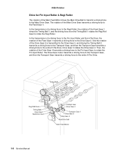
... Gear 2. In the transmission of a driving force to the Regi Roller, the rotation of the Feed Gear 1 transmits a driving force to the entire H-Tra Drive. 1-8 Service Manual Drive Gear 3 rotates the Drive Gear 4.
... Gear 2. In the transmission of a driving force to the Regi Roller, the rotation of the Feed Gear 1 transmits a driving force to the entire H-Tra Drive. 1-8 Service Manual Drive Gear 3 rotates the Drive Gear 4.

Service Manual
Page 22
... Gear is transmitted to the Punch Gear 1 via the Punch Gear 2. The counterclockwise rotation of the Punch Motor moves up and down the shaft. 1-10 Service Manual The rotation of the Main Drive Gear transmits a driving force to the Main Drive Gear. The rotation of the Feed Gear 1 drives the Timing Belt...
... Gear is transmitted to the Punch Gear 1 via the Punch Gear 2. The counterclockwise rotation of the Punch Motor moves up and down the shaft. 1-10 Service Manual The rotation of the Main Drive Gear transmits a driving force to the Main Drive Gear. The rotation of the Feed Gear 1 drives the Timing Belt...
Service Manual
Page 24
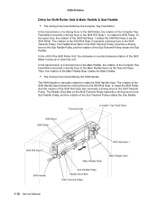
... the Shift Roller. In the transmission of a driving force to the Main Paddle, the rotation of the Sub Transmit Pulley rotates the Sub Paddle. 1-12 Service Manual The Paddle Drive Belt on the Shift Transmit Pulley transmits a driving force to the Sub Paddle Pulley, and the rotation of the Shift Roll Gear... unit. 4025-Finisher Drive for Shift Roller Unit & Main Paddle & Sub Paddle • The driving force transmitted by the Shift Handle The Shift Handle is manually rotated to rotate the Shift Handle Gear.
... the Shift Roller. In the transmission of a driving force to the Main Paddle, the rotation of the Sub Transmit Pulley rotates the Sub Paddle. 1-12 Service Manual The Paddle Drive Belt on the Shift Transmit Pulley transmits a driving force to the Sub Paddle Pulley, and the rotation of the Shift Roll Gear... unit. 4025-Finisher Drive for Shift Roller Unit & Main Paddle & Sub Paddle • The driving force transmitted by the Shift Handle The Shift Handle is manually rotated to rotate the Shift Handle Gear.

Service Manual
Page 26
And it also transmits the driving force transmitted from the Shift Handle Gear to the Shift Transmit Pulley, when rotating the Shift Handle manually. • The Shift Transmit Pulley transmits the driving force transmitted from the Shift Roll Gear 2 to the Paddle Drive Belt via the Shift Transmit Pulley. &#... Shift Roller to the Sub Paddle Pulley. • Driving the Sub Paddle Pulley rotates the Shift Transmit Pulley, and the Sub Paddle is rotated. 1-14 Service Manual
And it also transmits the driving force transmitted from the Shift Handle Gear to the Shift Transmit Pulley, when rotating the Shift Handle manually. • The Shift Transmit Pulley transmits the driving force transmitted from the Shift Roll Gear 2 to the Paddle Drive Belt via the Shift Transmit Pulley. &#... Shift Roller to the Sub Paddle Pulley. • Driving the Sub Paddle Pulley rotates the Shift Transmit Pulley, and the Sub Paddle is rotated. 1-14 Service Manual

Service Manual
Page 28
... Move Tray, via the Exit Roll Gear. The Compiler Move Tray is pushed out toward the paper delivery direction by the transmitted driving force. 1-16 Service Manual The Move Tray Belt transmits a driving force to the Com Drive Gear 1 on the Compiler Drive Shaft, to the Move Tray Belt. The Compiler Drive...
... Move Tray, via the Exit Roll Gear. The Compiler Move Tray is pushed out toward the paper delivery direction by the transmitted driving force. 1-16 Service Manual The Move Tray Belt transmits a driving force to the Com Drive Gear 1 on the Compiler Drive Shaft, to the Move Tray Belt. The Compiler Drive...

Service Manual
Page 30
... Shaft to the gear on the back of the Compiler Drive Shaft transmits a driving force to move the Compiler Move Tray forward or backward. 1-18 Service Manual
... Shaft to the gear on the back of the Compiler Drive Shaft transmits a driving force to move the Compiler Move Tray forward or backward. 1-18 Service Manual

Service Manual
Page 32
... force to the Sector Gear in the Stapler Unit, and the Sector Gear swings the Stapler Unit toward +45° or -45° direction. 1-20 Service Manual Then, the Stapler Swing Gear 2 transmits a driving force to the Stapler Swing Gear 2.
... force to the Sector Gear in the Stapler Unit, and the Sector Gear swings the Stapler Unit toward +45° or -45° direction. 1-20 Service Manual Then, the Stapler Swing Gear 2 transmits a driving force to the Stapler Swing Gear 2.

Service Manual
Page 34
... to each gear on the Elevator Drive Unit via the Lift Up Gear 1. The rotation of the Lift Up Gear 3 rotates the Liner Encoder. 1-22 Service Manual The rotation of the Elevator shaft transmits a driving force to the Elevator Belt to swing the unit. • The Stapler Swing HP Sensor detects the...
... to each gear on the Elevator Drive Unit via the Lift Up Gear 1. The rotation of the Lift Up Gear 3 rotates the Liner Encoder. 1-22 Service Manual The rotation of the Elevator shaft transmits a driving force to the Elevator Belt to swing the unit. • The Stapler Swing HP Sensor detects the...

Service Manual
Page 36
... Mechanical Stacker Tray Components • The Lift Up Motor supplies a driving force to the Elevator Shaft via each gear rotates the Exit Top Roller. 1-24 Service Manual Then, the rotation of each gear on the Elevator Drive Unit. • The Elevator Drive Unit supplies the driving force generated by the Lift Up...
... Mechanical Stacker Tray Components • The Lift Up Motor supplies a driving force to the Elevator Shaft via each gear rotates the Exit Top Roller. 1-24 Service Manual Then, the rotation of each gear on the Elevator Drive Unit. • The Elevator Drive Unit supplies the driving force generated by the Lift Up...

Service Manual
Page 38
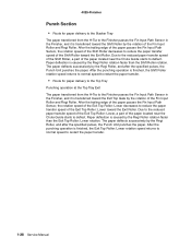
...-Finisher Finisher Paper Path Main mechanisms in the Finisher are described by paper transfer path, as follows: • H-Tra: Mechanism to transfer paper from the printer to the Finisher. • Punch section: Mechanism to punch paper. • Shift section: Mechanism to shift paper toward the front or rear. • Compile & Jogging... up or down the Stacker Tray according to the stacking volume. • Top Tray Exit section: Mechanism to deliver paper to the Top Tray. 1-26 Service Manual
...-Finisher Finisher Paper Path Main mechanisms in the Finisher are described by paper transfer path, as follows: • H-Tra: Mechanism to transfer paper from the printer to the Finisher. • Punch section: Mechanism to punch paper. • Shift section: Mechanism to shift paper toward the front or rear. • Compile & Jogging... up or down the Stacker Tray according to the stacking volume. • Top Tray Exit section: Mechanism to deliver paper to the Top Tray. 1-26 Service Manual
Service Manual
Page 40
... Unit punches the paper. Paper deflection is finished, the Exit Top Roller: Lower rotation speed returns to normal speed to restart the paper transfer. 1-28 Service Manual The paper deflects successively by the Regi Roller, and after the specified pulses, the Punch Unit punches the paper. After the punching operation is caused...
... Unit punches the paper. Paper deflection is finished, the Exit Top Roller: Lower rotation speed returns to normal speed to restart the paper transfer. 1-28 Service Manual The paper deflects successively by the Regi Roller, and after the specified pulses, the Punch Unit punches the paper. After the punching operation is caused...

Service Manual
Page 44
... is performed. Note: The shift job cannot be executed if the stapling job is executed. Also, each time a sheet of the Shift Roller Unit. 1-32 Service Manual Then, the Shift Roller Unit is moved forward or backward, the Exit Pinch Roll Guide closes and the Exit Roller rotates to the home position...
... is performed. Note: The shift job cannot be executed if the stapling job is executed. Also, each time a sheet of the Shift Roller Unit. 1-32 Service Manual Then, the Shift Roller Unit is moved forward or backward, the Exit Pinch Roll Guide closes and the Exit Roller rotates to the home position...

Service Manual
Page 48
... paper. • The Stapler Traverse HP Sensor detects the absolute position of the Stapler Unit from the presence of a notch on the guide rail. 1-36 Service Manual When performing the stapling, the Stapler Unit starts moving along rails to the Stacker Tray via the Exit section. After the Stapler staples the bundle...
... paper. • The Stapler Traverse HP Sensor detects the absolute position of the Stapler Unit from the presence of a notch on the guide rail. 1-36 Service Manual When performing the stapling, the Stapler Unit starts moving along rails to the Stacker Tray via the Exit section. After the Stapler staples the bundle...

Service Manual
Page 50
4025-Finisher Exit Components • The Exit Roller delivers paper to the Stacker Tray, and transfers paper to the Compiler Tray. • The Exit Pinch Roll Guide nips the paper with the Exit Roller to assist the paper to be delivered. • The Paper Exit Sensor monitors the paper passing condition on the Exit Pinch Roll Guide. • The Exit Roller Open/Close HP Sensor detects whether the Exit Pinch Roll Guide is in the home position. 1-38 Service Manual
4025-Finisher Exit Components • The Exit Roller delivers paper to the Stacker Tray, and transfers paper to the Compiler Tray. • The Exit Pinch Roll Guide nips the paper with the Exit Roller to assist the paper to be delivered. • The Paper Exit Sensor monitors the paper passing condition on the Exit Pinch Roll Guide. • The Exit Roller Open/Close HP Sensor detects whether the Exit Pinch Roll Guide is in the home position. 1-38 Service Manual
Service Manual
Page 56
.... °C = 0.55 (°F - 32) Counterclockwise The negative voltage that the High Voltage Power Supply applies to toggle a switch or a sensor Auxiliary B- Earth Electrical ground 1-44 Service Manual The measure of paper E- 4025-Finisher Glossary of approximately 0 ohms The electrical interface between the printer MCU and the host computer.
.... °C = 0.55 (°F - 32) Counterclockwise The negative voltage that the High Voltage Power Supply applies to toggle a switch or a sensor Auxiliary B- Earth Electrical ground 1-44 Service Manual The measure of paper E- 4025-Finisher Glossary of approximately 0 ohms The electrical interface between the printer MCU and the host computer.
Service Manual
Page 58
... Unit. A male electrical connector A sheet of paper stops at a point along the paper path The path a sheet of the printer Mailbox Motor No Connection Non-Volatile Random Access Memory Transparency print media Open Diagnostic routine used in the Printhead The invisible, electrical image ...Laser Diode to the surface of the drum Semiconductor device that generates the laser beam used to the output tray Paper Handling Plug and Jack. Electrical connectors as a unit Parts List Pages Per Minute or Prints Per Minute J- MCU MBX MOT N- P Paper jam Paper path P/H P/J PL PPM 1-46 Service Manual...
... Unit. A male electrical connector A sheet of paper stops at a point along the paper path The path a sheet of the printer Mailbox Motor No Connection Non-Volatile Random Access Memory Transparency print media Open Diagnostic routine used in the Printhead The invisible, electrical image ...Laser Diode to the surface of the drum Semiconductor device that generates the laser beam used to the output tray Paper Handling Plug and Jack. Electrical connectors as a unit Parts List Pages Per Minute or Prints Per Minute J- MCU MBX MOT N- P Paper jam Paper path P/H P/J PL PPM 1-46 Service Manual...

Service Manual
Page 60
Wire Harness 4025-Finisher A bundle of wires that form a single unit and are generally terminated with connectors at both ends 1-48 Service Manual
Wire Harness 4025-Finisher A bundle of wires that form a single unit and are generally terminated with connectors at both ends 1-48 Service Manual

Service Manual
Page 62
.... Generally, no user intervention is in the Operator Intervention state. However, it is intermittent in nature. When a Service Message occurs, the printer stops printing. When an operator intervention condition occurs, all host links will be started when the Load Paper message is...stopped while the printer is required. All timeouts will be possible to power off and back on the current state of the operator intervention condition. The operator is displayed for the manual source. 2-2 Service Manual In general, service errors are displayed when the printer is to power...
.... Generally, no user intervention is in the Operator Intervention state. However, it is intermittent in nature. When a Service Message occurs, the printer stops printing. When an operator intervention condition occurs, all host links will be started when the Load Paper message is...stopped while the printer is required. All timeouts will be possible to power off and back on the current state of the operator intervention condition. The operator is displayed for the manual source. 2-2 Service Manual In general, service errors are displayed when the printer is to power...


