
Service Manual
Page 5
... Diagnostic aids 3-1 Accessing service menus 3-1 Diagnostics mode 3-2 Entering Diagnostics mode 3-2 Available tests 3-2 Exiting Diagnostics mode 3-4 REGISTRATION 3-4 Quick Test 3-5 PRINT TESTS 3-6 Input source tests 3-6 Print quality pages (Prt Quality Pgs 3-6 HARDWARE TESTS 3-7 Panel Test 3-7 Button Test 3-7 DRAM Test 3-7 CACHE Test 3-8 Parallel Wrap tests 3-8 Serial Wrap tests 3-9 DUPLEX TESTS 3-9 Quick Test (duplex 3-9 Top Margin (duplex 3-10 Sensor Test (duplex 3-10 Motor Test (duplex 3-11 Duplex Feed 1 3-12 Duplex Feed 2 3-12 INPUT TRAY TESTS 3-13 Feed Tests...
... Diagnostic aids 3-1 Accessing service menus 3-1 Diagnostics mode 3-2 Entering Diagnostics mode 3-2 Available tests 3-2 Exiting Diagnostics mode 3-4 REGISTRATION 3-4 Quick Test 3-5 PRINT TESTS 3-6 Input source tests 3-6 Print quality pages (Prt Quality Pgs 3-6 HARDWARE TESTS 3-7 Panel Test 3-7 Button Test 3-7 DRAM Test 3-7 CACHE Test 3-8 Parallel Wrap tests 3-8 Serial Wrap tests 3-9 DUPLEX TESTS 3-9 Quick Test (duplex 3-9 Top Margin (duplex 3-10 Sensor Test (duplex 3-10 Motor Test (duplex 3-11 Duplex Feed 1 3-12 Duplex Feed 2 3-12 INPUT TRAY TESTS 3-13 Feed Tests...
Service Manual
Page 41
...; "StapleSmart finisher" on page 2-44. Additional information • "Power-On Self Test (POST) sequence" on page 2-4 • "Understanding the printer operator panel" on page 2-2 • "Understanding the menus" on page 2-3 • "Diagnostics mode" on page 3-2 • "Configuration menu (CONFIG MENU)" on page 3-25... • "Theory" on page 3-31 • "Paper feed jams" on page 3-37 • "Parts catalog" on the machine, go to ...
...; "StapleSmart finisher" on page 2-44. Additional information • "Power-On Self Test (POST) sequence" on page 2-4 • "Understanding the printer operator panel" on page 2-2 • "Understanding the menus" on page 2-3 • "Diagnostics mode" on page 3-2 • "Configuration menu (CONFIG MENU)" on page 3-25... • "Theory" on page 3-31 • "Paper feed jams" on page 3-37 • "Parts catalog" on the machine, go to ...
Service Manual
Page 112
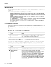
..." on page 2-8 to help diagnose the problem. • Print quality problems: Go to "Print quality pages (Prt Quality Pgs)" on page 3-6 and print a test page to see if the printer recognizes any settings or working on the cable. Check the voltages on each one to help isolate a problem before... of the printer or option. • Paper feed problems with error message: Use the "Sub error codes for the failing output option. Also check to make sure to move it back to its original position on the printer. • Use the resident diagnostics test provided to service the unit. FRU 1 5-Bin...
..." on page 2-8 to help diagnose the problem. • Print quality problems: Go to "Print quality pages (Prt Quality Pgs)" on page 3-6 and print a test page to see if the printer recognizes any settings or working on the cable. Check the voltages on each one to help isolate a problem before... of the printer or option. • Paper feed problems with error message: Use the "Sub error codes for the failing output option. Also check to make sure to move it back to its original position on the printer. • Use the resident diagnostics test provided to service the unit. FRU 1 5-Bin...
Service Manual
Page 136
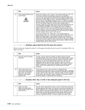
... replace the switch cable. 2-96 Service Manual Short pins 1 and 2 together while observing the sensor test on the rollers. Check these parts for any problems. +24 V dc must come from the diagnostics menu. If incorrect, disconnect the cable at J9 and check the voltage again. If incorrect, check ...connector. If no problem is a Paper Jam Tray 2 FRU 1 Pass thru sensor and flag assembly 2 Power takeoff shaft and spring, bevel gear, feed roll gear, drive roll assembly, wear plate, drive shaft bearings, and skewed backup roller Action The tray x option system board did not detect a ...
... replace the switch cable. 2-96 Service Manual Short pins 1 and 2 together while observing the sensor test on the rollers. Check these parts for any problems. +24 V dc must come from the diagnostics menu. If incorrect, disconnect the cable at J9 and check the voltage again. If incorrect, check ...connector. If no problem is a Paper Jam Tray 2 FRU 1 Pass thru sensor and flag assembly 2 Power takeoff shaft and spring, bevel gear, feed roll gear, drive roll assembly, wear plate, drive shaft bearings, and skewed backup roller Action The tray x option system board did not detect a ...

Service Manual
Page 143
... board). If no problem is a Paper Jam Tray 1) FRU 1 Pass thru sensor and flag assembly 2 Power takeoff shaft and spring, bevel gear, feed roll gear, drive roll assembly, wear plate, drive shaft bearings, and skewed backup roller Action The tray x option system board did not detect a piece...displays, paper jammed over the pass thru sensor (The printer displays the value of x for proper operation by running the appropriate Tray Sensor Test from the diagnostics menu. Remove any jammed sheets of paper from the printer or option above tray x. If incorrect, replace the tray x option pass thru...
... board). If no problem is a Paper Jam Tray 1) FRU 1 Pass thru sensor and flag assembly 2 Power takeoff shaft and spring, bevel gear, feed roll gear, drive roll assembly, wear plate, drive shaft bearings, and skewed backup roller Action The tray x option system board did not detect a piece...displays, paper jammed over the pass thru sensor (The printer displays the value of x for proper operation by running the appropriate Tray Sensor Test from the diagnostics menu. Remove any jammed sheets of paper from the printer or option above tray x. If incorrect, replace the tray x option pass thru...

Service Manual
Page 151
... board. Check Bin x, POST complete, first sheet of paper feeds into output bin x Note: Before performing the following checks, run the Output Bin X Sensor Test and check for proper operation. The voltage measures approximately +5 V dc. Sensor Test: NF = Near Full (Upper part of sensor assembly) F... sensor and flag assembly Control board Action Check the sensor flag for the failing sensor. If incorrect, replace the control board. Diagnostic information 2-111 If incorrect, replace the sensor assembly. If correct, check to make sure the pass thru sensor cable is incorrect...
... board. Check Bin x, POST complete, first sheet of paper feeds into output bin x Note: Before performing the following checks, run the Output Bin X Sensor Test and check for proper operation. The voltage measures approximately +5 V dc. Sensor Test: NF = Near Full (Upper part of sensor assembly) F... sensor and flag assembly Control board Action Check the sensor flag for the failing sensor. If incorrect, replace the control board. Diagnostic information 2-111 If incorrect, replace the sensor assembly. If correct, check to make sure the pass thru sensor cable is incorrect...

Service Manual
Page 165
...If the problem continues, go to remove the cartridge holder from the diagnostic menu. Diagnostic information 2-125 FRU 1 Stapler cartridge holder Stapler assembly 2 Stapler to free the cartridge holder assembly. It may try the finisher feed test from the stapler assembly. The stapler assembly may be in the cartridge...spring are found , replace the stapler assembly. Check the flag and spring assembly on the side of the cable. Run the Finisher Feed Test to drop. 4. Check for correct operation and for staples jammed at the throat of the stapler assembly to hang by the switch...
...If the problem continues, go to remove the cartridge holder from the diagnostic menu. Diagnostic information 2-125 FRU 1 Stapler cartridge holder Stapler assembly 2 Stapler to free the cartridge holder assembly. It may try the finisher feed test from the stapler assembly. The stapler assembly may be in the cartridge...spring are found , replace the stapler assembly. Check the flag and spring assembly on the side of the cable. Run the Finisher Feed Test to drop. 4. Check for correct operation and for staples jammed at the throat of the stapler assembly to hang by the switch...

Service Manual
Page 171
4061-xx0 Diagnostics mode tests (continued) DUPLEX TESTS (if installed) Quick Test Top Margin Sensor Test Motor Test Duplex Feed 1 Duplex Feed 2 INPUT TRAY TESTS Feed Tests Sensor Test OUTPUT BIN TESTS Feed Tests Feed To All Bins Sensor Test Diverter Test (if 5-bin installed) FINISHER TESTS (if installed) Staple Test Feed Tests Sensor Test BASE SENSOR TEST Toner Input Output DEVICE TESTS Quick Disk Test (if installed) Disk Test/Clean (if installed) Flash Test (if installed) PRINTER SETUP...
4061-xx0 Diagnostics mode tests (continued) DUPLEX TESTS (if installed) Quick Test Top Margin Sensor Test Motor Test Duplex Feed 1 Duplex Feed 2 INPUT TRAY TESTS Feed Tests Sensor Test OUTPUT BIN TESTS Feed Tests Feed To All Bins Sensor Test Diverter Test (if 5-bin installed) FINISHER TESTS (if installed) Staple Test Feed Tests Sensor Test BASE SENSOR TEST Toner Input Output DEVICE TESTS Quick Disk Test (if installed) Disk Test/Clean (if installed) Flash Test (if installed) PRINTER SETUP...

Service Manual
Page 174
...-xx0 PRINT TESTS Input source tests The purpose of the diagnostic Print Tests is turned on, the pages are printed in print quality and paper feed problems. To run the Print Quality Test Pages, select Prt Quality Pgs from the Diagnostics menu. 2. The contents of the Print Test Page varies ...depending on the media installed in DIAGNOSTICS, including: Fuser temperature, warm up time, transfer...
...-xx0 PRINT TESTS Input source tests The purpose of the diagnostic Print Tests is turned on, the pages are printed in print quality and paper feed problems. To run the Print Quality Test Pages, select Prt Quality Pgs from the Diagnostics menu. 2. The contents of the Print Test Page varies ...depending on the media installed in DIAGNOSTICS, including: Fuser temperature, warm up time, transfer...

Service Manual
Page 179
4061-xx0 Motor Test (duplex) This test lets you test the duplex option paper feed drive system, and verify that the power and velocity values are displayed. For the duplex DC motor to pass the test, the following results must display: •... inclusively (hex) • DD = in the range of the test. Diagnostic aids 3-11 The duplex runs the DC motor at high speed and low speed, taking an average of the... for the low speed portion of the power (PWM) required for the low speed portion of the test The results should be in the range of 20 through 3F inclusively (hex) • CC-average ...
4061-xx0 Motor Test (duplex) This test lets you test the duplex option paper feed drive system, and verify that the power and velocity values are displayed. For the duplex DC motor to pass the test, the following results must display: •... inclusively (hex) • DD = in the range of the test. Diagnostic aids 3-11 The duplex runs the DC motor at high speed and low speed, taking an average of the... for the low speed portion of the power (PWM) required for the low speed portion of the test The results should be in the range of 20 through 3F inclusively (hex) • CC-average ...

Service Manual
Page 181
... run the Input Tray Sensor Test: 1. To run the Input Tray Feed Tests: 1. Select the sensor to exit the test. The paper is used to determine if the input tray sensors are working correctly. Once this test. When the sensor is open the lower front door that is feeding through the printer. Diagnostic aids 3-13 when the...
... run the Input Tray Sensor Test: 1. To run the Input Tray Feed Tests: 1. Select the sensor to exit the test. The paper is used to determine if the input tray sensors are working correctly. Once this test. When the sensor is open the lower front door that is feeding through the printer. Diagnostic aids 3-13 when the...

Service Manual
Page 185
...the Feed Test, select Feed Tests from FINISHER TESTS. 2. Note: This test can be used to the finisher output bins. To run the Staple Test: 1. While the test runs the power indicator blinks and the message Staple Test Running... displays. Select Sensor Test from FINISHER TESTS. Sensor Test (finisher) This test can be cancelled until the test is complete. 4061-xx0 FINISHER TESTS Staple Test This test... pass thru Media sensor • Bin Level Finisher bin empty Bin full sensor Bin near full 3. Select one of blank paper are working correctly. Diagnostic aids 3-17
...the Feed Test, select Feed Tests from FINISHER TESTS. 2. Note: This test can be used to the finisher output bins. To run the Staple Test: 1. While the test runs the power indicator blinks and the message Staple Test Running... displays. Select Sensor Test from FINISHER TESTS. Sensor Test (finisher) This test can be cancelled until the test is complete. 4061-xx0 FINISHER TESTS Staple Test This test... pass thru Media sensor • Bin Level Finisher bin empty Bin full sensor Bin near full 3. Select one of blank paper are working correctly. Diagnostic aids 3-17

Service Manual
Page 406
... 4-79 developer drive assembly parts 7-22 removal 4-24 developer drive coupler kit 4-25 diagnostics mode 3-2 accessing 3-1 available tests 3-2 BASE SENSOR TEST 3-18 DEVICE TESTS Disk Test/Clean 3-19 Flash Test 3-19 Quick Disk Test 3-18 DUPLEX TESTS Duplex Feed 1 3-12 Duplex Feed 2 3-12 Motor Test 3-11 Quick Test 3-9 Sensor Test 3-10 Top Margin 3-10 EP SETUP Charge Roll 3-22 EP Defaults 3-22 Fuser...
... 4-79 developer drive assembly parts 7-22 removal 4-24 developer drive coupler kit 4-25 diagnostics mode 3-2 accessing 3-1 available tests 3-2 BASE SENSOR TEST 3-18 DEVICE TESTS Disk Test/Clean 3-19 Flash Test 3-19 Quick Disk Test 3-18 DUPLEX TESTS Duplex Feed 1 3-12 Duplex Feed 2 3-12 Motor Test 3-11 Quick Test 3-9 Sensor Test 3-10 Top Margin 3-10 EP SETUP Charge Roll 3-22 EP Defaults 3-22 Fuser...
