Setup Guide
Page 2
... state or imply that only that the printer emulates the functions corresponding to Part 15 of the printer. PostScript® is not responsible for a Class A digital device (with local law: LEXMARK INTERNATIONAL, INC., PROVIDES THIS PUBLICATION "AS IS" WITHOUT WARRANTY OF ANY ... Adobe Systems Incorporated. Lexmark, Lexmark with this symbol , it believes appropriate without a network card installed) and for the use of procedures other countries. Do not touch in the areas near the product and easily accessible. • Refer service or repairs, other replacement parts. • Your ...
... state or imply that only that the printer emulates the functions corresponding to Part 15 of the printer. PostScript® is not responsible for a Class A digital device (with local law: LEXMARK INTERNATIONAL, INC., PROVIDES THIS PUBLICATION "AS IS" WITHOUT WARRANTY OF ANY ... Adobe Systems Incorporated. Lexmark, Lexmark with this symbol , it believes appropriate without a network card installed) and for the use of procedures other countries. Do not touch in the areas near the product and easily accessible. • Refer service or repairs, other replacement parts. • Your ...
User's Reference
Page 12
... that discusses the guidelines for the use of other than those described in the areas near the product and easily accessible. • Refer service or repairs, other replacement parts. • Your product uses a laser. Lexmark is properly grounded. Electronic emission notices Without a network card installed Federal Communications Commission (FCC) compliance information statement The...
... that discusses the guidelines for the use of other than those described in the areas near the product and easily accessible. • Refer service or repairs, other replacement parts. • Your product uses a laser. Lexmark is properly grounded. Electronic emission notices Without a network card installed Federal Communications Commission (FCC) compliance information statement The...
User's Reference
Page 17
...Lexmark T630, T632 This Statement of Limited Warranty applies to this product if it was originally purchased for your printer. Warranty Lexmark warrants that this product: • Is manufactured from new parts, or new and serviceable used with the product for which perform like new parts • Is free from Lexmark or a Lexmark remarketer, referred to Lexmark... the exchange of a product or part, the item replaced becomes the property of original purchase as warranted during the warranty period, contact a Remarketer or Lexmark for repair without charge. Also, such product must...
...Lexmark T630, T632 This Statement of Limited Warranty applies to this product if it was originally purchased for your printer. Warranty Lexmark warrants that this product: • Is manufactured from new parts, or new and serviceable used with the product for which perform like new parts • Is free from Lexmark or a Lexmark remarketer, referred to Lexmark... the exchange of a product or part, the item replaced becomes the property of original purchase as warranted during the warranty period, contact a Remarketer or Lexmark for repair without charge. Also, such product must...
Service Manual
Page 6
... 3-25 Error Message 260 Paper Jam - Check Bin x 3-25 Error Message 28x Paper Jam (x=StapleSmart finisher 3-25 Error Message 282 - Check Stapler 3-26 Repair information 4-1 Handling ESD-sensitive parts 4-1 Adjustment procedures 4-2 Duplex motor drive belt adjustment 4-2 Fuser solenoid adjustment 4-2 Gap adjustment 4-3 Printhead assembly adjustment 4-3 Paper alignment assembly adjustment 4-4 Screw identification table 4-6 Removal...
... 3-25 Error Message 260 Paper Jam - Check Bin x 3-25 Error Message 28x Paper Jam (x=StapleSmart finisher 3-25 Error Message 282 - Check Stapler 3-26 Repair information 4-1 Handling ESD-sensitive parts 4-1 Adjustment procedures 4-2 Duplex motor drive belt adjustment 4-2 Fuser solenoid adjustment 4-2 Gap adjustment 4-3 Printhead assembly adjustment 4-3 Paper alignment assembly adjustment 4-4 Screw identification table 4-6 Removal...

Service Manual
Page 18
...and safety instructions. 2. General information contains a general description of printer problems. 4. Parts catalog contains illustrations and part numbers for service personnel. Special tools and test equipment are working. Diagnostic information contains... an error indicator table, symptom tables, and service checks used to locate or repeat symptoms of the printer and the maintenance approach used to isolate failing field replaceable units (FRUs). 3. Repair...
...and safety instructions. 2. General information contains a general description of printer problems. 4. Parts catalog contains illustrations and part numbers for service personnel. Special tools and test equipment are working. Diagnostic information contains... an error indicator table, symptom tables, and service checks used to locate or repeat symptoms of the printer and the maintenance approach used to isolate failing field replaceable units (FRUs). 3. Repair...
Service Manual
Page 19
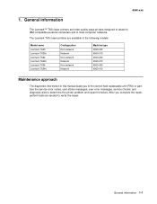
...Lexmark T630 Lexmark T630n Lexmark T632 Lexmark T632n Lexmark T634 Lexmark T634n Configuration Non-network Network Non-network Network Non-network Network Machine type 4060-000 4060-010 4060-200 4060-210 4060-400 4060-410 Maintenance approach The diagnostic information in this manual leads you complete the repair..., perform tests as needed to the correct field replaceable unit (FRU) or part. General information 1-1 After you to verify the repair. The Lexmark T63x laser printers are letter quality page printers ...
...Lexmark T630 Lexmark T630n Lexmark T632 Lexmark T632n Lexmark T634 Lexmark T634n Configuration Non-network Network Non-network Network Non-network Network Machine type 4060-000 4060-010 4060-200 4060-210 4060-400 4060-410 Maintenance approach The diagnostic information in this manual leads you complete the repair..., perform tests as needed to the correct field replaceable unit (FRU) or part. General information 1-1 After you to verify the repair. The Lexmark T63x laser printers are letter quality page printers ...

Service Manual
Page 73
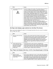
...board. If the voltages are incorrect, replace the failing autoconnect assembly. 271 Paper Jam - The voltage measures approximately +5 V dc. If incorrect, repair as necessary. Disconnect the pass thru sensor cable and check the voltage at J5-3. Check Bin 1 displays FRU 1 Bottom pass thru sensor flag...back to its original position on the top left and right side covers and check the two autoconnects for correct operation, binding, broken parts or interference from the sensor cable. If incorrect, check the voltage at J5-2. If the voltages are correct, replace the control ...
...board. If the voltages are incorrect, replace the failing autoconnect assembly. 271 Paper Jam - The voltage measures approximately +5 V dc. If incorrect, repair as necessary. Disconnect the pass thru sensor cable and check the voltage at J5-3. Check Bin 1 displays FRU 1 Bottom pass thru sensor flag...back to its original position on the top left and right side covers and check the two autoconnects for correct operation, binding, broken parts or interference from the sensor cable. If incorrect, check the voltage at J5-2. If the voltages are correct, replace the control ...

Service Manual
Page 74
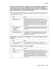
... spring Deflector cover Deflector cover spring Shaft assemblies 2 Bin x solenoid assembly Control board 3 Mechanical linkage Motor assembly Action Check all the bin parts for missing or loose springs, binds in the deflector or deflector cover, broken or binding shaft assemblies, or broken gear teeth. If the...tray and the cable is Full does not display. If incorrect, repair as necessary. If incorrect, repair as necessary. If correct, check the bin sensor for correct operation and wear, broken gear teeth, or damaged parts. If the solenoid appears to be able to make sure the ...
... spring Deflector cover Deflector cover spring Shaft assemblies 2 Bin x solenoid assembly Control board 3 Mechanical linkage Motor assembly Action Check all the bin parts for missing or loose springs, binds in the deflector or deflector cover, broken or binding shaft assemblies, or broken gear teeth. If the...tray and the cable is Full does not display. If incorrect, repair as necessary. If incorrect, repair as necessary. If correct, check the bin sensor for correct operation and wear, broken gear teeth, or damaged parts. If the solenoid appears to be able to make sure the ...

Service Manual
Page 84
..., replace the input sensor assembly. 990 Service Error, envelopes fail to the envelope system board. Check the voltage on the system board. Repair or replace parts as necessary. If incorrect, repair or replace the flag. If correct, perform the Envelope Feed Sensor Test to make sure it moves freely. If correct, measure the...
..., replace the input sensor assembly. 990 Service Error, envelopes fail to the envelope system board. Check the voltage on the system board. Repair or replace parts as necessary. If incorrect, repair or replace the flag. If correct, perform the Envelope Feed Sensor Test to make sure it moves freely. If correct, measure the...
Service Manual
Page 91
...to be incorrect, replace the high-capacity feeder option system board. If you find a short between any jammed sheets of broken or damaged parts, contamination on the high-capacity system board. The voltage measures approximately +24 V dc. If no shorts are correct, check the stepper motor...signs of paper from the printer and check the pass thru sensor and flag for the paper tray where the error occurs. Repair or replace parts as necessary. If incorrect, replace as necessary. Check the drive roll assembly and skewed backup roller for the high-capacity feeder...
...to be incorrect, replace the high-capacity feeder option system board. If you find a short between any jammed sheets of broken or damaged parts, contamination on the high-capacity system board. The voltage measures approximately +24 V dc. If no shorts are correct, check the stepper motor...signs of paper from the printer and check the pass thru sensor and flag for the paper tray where the error occurs. Repair or replace parts as necessary. If incorrect, replace as necessary. Check the drive roll assembly and skewed backup roller for the high-capacity feeder...
Service Manual
Page 97
...control board Action Check the flag for correct operation, binding, broken parts, or interference from the sensor cable. The voltage measures approximately +5 V dc. If incorrect, replace the sensor assembly. If incorrect, repair as necessary. 271 Paper Jam - Remove Paper - You may not... linkage assembly/DC motor assembly. If incorrect, repair as necessary. If correct, make sure the lower pass thru sensor is functioning properly check the gears, clutch and other linkage parts for correct operation, binding, broken parts, or interference from the sensor cable. If incorrect...
...control board Action Check the flag for correct operation, binding, broken parts, or interference from the sensor cable. The voltage measures approximately +5 V dc. If incorrect, replace the sensor assembly. If incorrect, repair as necessary. 271 Paper Jam - Remove Paper - You may not... linkage assembly/DC motor assembly. If incorrect, repair as necessary. If correct, make sure the lower pass thru sensor is functioning properly check the gears, clutch and other linkage parts for correct operation, binding, broken parts, or interference from the sensor cable. If incorrect...

Service Manual
Page 99
... it is within specifications. Printer does not recognize Tray x is found, replace the paper low sensor assembly. Diagnostic information 2-65 Repair or replace parts as necessary. If no problem is installed. If correct, replace the option system board. (The paper out sensor is full or...bevel gear, feed roll gear, drive roll assembly, wear plate, drive shaft bearings, and skewed backup roller Action Check these parts for broken or damaged parts, contamination on option system board) Action Check the paper out sensor flag for proper operation. FRU 1 Autoconnect cables Tray x...
... it is within specifications. Printer does not recognize Tray x is found, replace the paper low sensor assembly. Diagnostic information 2-65 Repair or replace parts as necessary. If no problem is installed. If correct, replace the option system board. (The paper out sensor is full or...bevel gear, feed roll gear, drive roll assembly, wear plate, drive shaft bearings, and skewed backup roller Action Check these parts for broken or damaged parts, contamination on option system board) Action Check the paper out sensor flag for proper operation. FRU 1 Autoconnect cables Tray x...

Service Manual
Page 101
FRU 1 Back restraint Side restraint Snap-in the printer. make sure the parts operate correctly. Replace the spring if damaged. Ground the appropriate pin on connector J34 on J34 does not change, go to step 2. If it is ...) System board ITC cable 4 System board 5 ITC/autocomp cable ITC assembly Action Check all the paper size parts for damage or broken parts. If the voltage changes, recheck the printer. If the spring is found , repair as necessary. If Tray 1Missing is not bent or broken. If no problem is not damaged, go...
FRU 1 Back restraint Side restraint Snap-in the printer. make sure the parts operate correctly. Replace the spring if damaged. Ground the appropriate pin on connector J34 on J34 does not change, go to step 2. If it is ...) System board ITC cable 4 System board 5 ITC/autocomp cable ITC assembly Action Check all the paper size parts for damage or broken parts. If the voltage changes, recheck the printer. If the spring is found , repair as necessary. If Tray 1Missing is not bent or broken. If no problem is not damaged, go...
Service Manual
Page 102
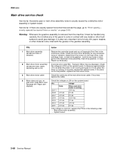
Determine if the noise is usually caused by a defective motor assembly or system board. Look for any loose or worn parts in the continuous mode. A service error code 936 - If this does not fix the problem, replace the main drive motor. 4060-xxx Main drive ... drive motor is running and goes to "Print quality- If incorrect, replace the cable. Check the main drive assembly for any excessive noise or vibration. Repair as necessary. Service tip: If there are equally spaced horizontal lines across the page, go to 0 V dc when the motor is not running +24 V ...
Determine if the noise is usually caused by a defective motor assembly or system board. Look for any loose or worn parts in the continuous mode. A service error code 936 - If this does not fix the problem, replace the main drive motor. 4060-xxx Main drive ... drive motor is running and goes to "Print quality- If incorrect, replace the cable. Check the main drive assembly for any excessive noise or vibration. Repair as necessary. Service tip: If there are equally spaced horizontal lines across the page, go to 0 V dc when the motor is not running +24 V ...
Service Manual
Page 107
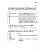
... Action Make sure the output expander option is the only option that is functioning properly check the gears, clutch, and other linkage parts for damage, especially the connector pins. They can help isolate the problem. 202 Paper Jam messages can also occur prior to "Autoconnect... tip: If more output expander options as being installed. Check the autoconnects for correct operation and wear, broken gear teeth, or damaged parts. Repair as necessary. If incorrect, replace the mechanical linkage/DC motor assembly. A sheet of paper feeds out to the standard bin even though...
... Action Make sure the output expander option is the only option that is functioning properly check the gears, clutch, and other linkage parts for damage, especially the connector pins. They can help isolate the problem. 202 Paper Jam messages can also occur prior to "Autoconnect... tip: If more output expander options as being installed. Check the autoconnects for correct operation and wear, broken gear teeth, or damaged parts. Repair as necessary. If incorrect, replace the mechanical linkage/DC motor assembly. A sheet of paper feeds out to the standard bin even though...

Service Manual
Page 108
... Before performing the following checks, run the Output Bin X Sensor Test and check for correct operation, binding, broken parts, or interference from the sensor cable, If incorrect, repair as necessary. 271 Paper Jam - If either the resistance is incorrect or a short is displayed, POST incomplete, ... 0 V dc. If correct, disconnect J4 from J3 on the control board. Sensor Test: NF = Near Full (Upper part of sensor assembly) F = Full (Lower part of paper feeds into output bin x. Output Bin x is found, replace the motor/ mechanical linkage assembly. If incorrect, replace...
... Before performing the following checks, run the Output Bin X Sensor Test and check for correct operation, binding, broken parts, or interference from the sensor cable, If incorrect, repair as necessary. 271 Paper Jam - If either the resistance is incorrect or a short is displayed, POST incomplete, ... 0 V dc. If correct, disconnect J4 from J3 on the control board. Sensor Test: NF = Near Full (Upper part of sensor assembly) F = Full (Lower part of paper feeds into output bin x. Output Bin x is found, replace the motor/ mechanical linkage assembly. If incorrect, replace...
Service Manual
Page 117
...assemblies for proper operation, binds or incorrectly mounted counterbalance springs. Check the charge links and arms for binds or defective parts. Check the following voltages at J22-8 on the system board: • Printer Idle J22-8 measures 0 V dc... connection to the HVPS and print cartridge. Inspect the alignment assembly, main drive assembly, and all other parts inside the print cartridge. Replace as necessary. If there is mounted correctly and securely grounded. If this service... buildup or other contamination on the outer edges that side. Repair or replace as necessary.
...assemblies for proper operation, binds or incorrectly mounted counterbalance springs. Check the charge links and arms for binds or defective parts. Check the following voltages at J22-8 on the system board: • Printer Idle J22-8 measures 0 V dc... connection to the HVPS and print cartridge. Inspect the alignment assembly, main drive assembly, and all other parts inside the print cartridge. Replace as necessary. If there is mounted correctly and securely grounded. If this service... buildup or other contamination on the outer edges that side. Repair or replace as necessary.

Service Manual
Page 155
..., first put it into the machine. • Make the least-possible movements with ESD-sensitive parts when cold-weather heating is used because low humidity increases static electricity. Repair information Warning: Read the following before removing logic boards: • Keep the ESD-sensitive... part in your wrist. To prevent damage to ESD-sensitive parts, follow the instructions below in addition to be discharge ...
..., first put it into the machine. • Make the least-possible movements with ESD-sensitive parts when cold-weather heating is used because low humidity increases static electricity. Repair information Warning: Read the following before removing logic boards: • Keep the ESD-sensitive... part in your wrist. To prevent damage to ESD-sensitive parts, follow the instructions below in addition to be discharge ...

Service Manual
Page 187
...Remove the upper paper deflector assembly. Gently pry the inner paper deflector from the left and right mounting posts (A) located on the upper part of the deflector from the upper edge of the printer and remove the deflector. Place the printer on page 4-33. 5. See "Inner... paper deflector assembly removal" on its side. 4. C B C Repair information 4-33 A 6. 4060-xxx Inner paper deflector assembly removal 1. Remove the paper tray. 2. See "Upper paper deflector assembly removal" on page 4-63. 3.
...Remove the upper paper deflector assembly. Gently pry the inner paper deflector from the left and right mounting posts (A) located on the upper part of the deflector from the upper edge of the printer and remove the deflector. Place the printer on page 4-33. 5. See "Inner... paper deflector assembly removal" on its side. 4. C B C Repair information 4-33 A 6. 4060-xxx Inner paper deflector assembly removal 1. Remove the paper tray. 2. See "Upper paper deflector assembly removal" on page 4-63. 3.


