User Manual
Page 140
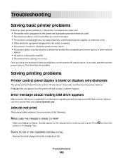
...about 10 seconds, and then turn the printer off by any switch or breaker. • The printer is not plugged into any surge protectors, uninterrupted power supplies, or extension cords. • Other electronic equipment plugged into the outlet is working. • The printer is supported. Try one or more of... drive appears Make sure the USB drive is turned on . For information regarding tested and approved USB flash memory devices, visit the Lexmark Web site at www.lexmark.com. Once you have checked each of the following: MAKE SURE THE PRINTER IS READY TO PRINT Make sure Ready or...
...about 10 seconds, and then turn the printer off by any switch or breaker. • The printer is not plugged into any surge protectors, uninterrupted power supplies, or extension cords. • Other electronic equipment plugged into the outlet is working. • The printer is supported. Try one or more of... drive appears Make sure the USB drive is turned on . For information regarding tested and approved USB flash memory devices, visit the Lexmark Web site at www.lexmark.com. Once you have checked each of the following: MAKE SURE THE PRINTER IS READY TO PRINT Make sure Ready or...

User Manual
Page 168
...modes may not apply to your product. Power consumption Product power consumption The following table documents the power consumption characteristics of the product. N/A Ready The product is waiting for a print job. 34 W (C540, C543); 36 W (C544) Power Saver The product is scanning hard-copy ...documents. Mode Printing Description The product is generating hard-copy output from electronic inputs. Power consumption (Watts) 480 W (C540, C543); 500 W (C544) Copying The product...
...modes may not apply to your product. Power consumption Product power consumption The following table documents the power consumption characteristics of the product. N/A Ready The product is waiting for a print job. 34 W (C540, C543); 36 W (C544) Power Saver The product is scanning hard-copy ...documents. Mode Printing Description The product is generating hard-copy output from electronic inputs. Power consumption (Watts) 480 W (C540, C543); 500 W (C544) Copying The product...
Service Manual
Page 6
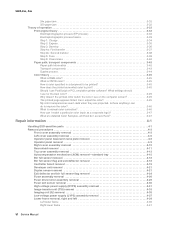
... Fuser assembly removal 4-26 Fuser drive motor assembly removal 4-29 Fuser exit sensor removal 4-30 High-voltage power supply (HVPS) assembly removal 4-31 Image transfer unit (ITU) removal 4-33 Imaging unit (IU) removal 4-35 Low-voltage power supply (LVPS) assembly removal 4-37 Lower frame removal, right and left 4-39 Left lower frame 4-39 Right...
... Fuser assembly removal 4-26 Fuser drive motor assembly removal 4-29 Fuser exit sensor removal 4-30 High-voltage power supply (HVPS) assembly removal 4-31 Image transfer unit (ITU) removal 4-33 Imaging unit (IU) removal 4-35 Low-voltage power supply (LVPS) assembly removal 4-37 Lower frame removal, right and left 4-39 Left lower frame 4-39 Right...

Service Manual
Page 7
... Waste toner bottle removal 4-60 Wireless network antenna removal 4-61 Wireless network card 4-63 Connector locations 5-1 Locations 5-1 Connectors 5-2 Controller board diagram 5-2 High-voltage power supply (HVPS) diagram 5-10 Low-voltage power supply (LVPS) diagram 5-12 Toner meter cycle (TMC) card 5-13 Wireless network card 5-14 Preventive maintenance 6-1 Safety inspection guide 6-1 Parts catalog 7-1 How to...
... Waste toner bottle removal 4-60 Wireless network antenna removal 4-61 Wireless network card 4-63 Connector locations 5-1 Locations 5-1 Connectors 5-2 Controller board diagram 5-2 High-voltage power supply (HVPS) diagram 5-10 Low-voltage power supply (LVPS) diagram 5-12 Toner meter cycle (TMC) card 5-13 Wireless network card 5-14 Preventive maintenance 6-1 Safety inspection guide 6-1 Parts catalog 7-1 How to...
Service Manual
Page 21
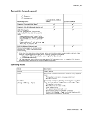
5025-2xx, 4xx Connectivity (network support) ✔-Supported ✘-Not supported Network protocol Lexmark C540n, C543dn, C544dn Lexmark C544dw Standard Ethernet 10/100 Base T ✔ ✔ Standard USB-B (Full speed) device port ✔ ✔ USB-A host ports ✘ ✔ (In ... is set to one minute. • Fuser standby is off. • The operator panel back light is off. • Power supply energy consumption is reduced. • Duplex is on if Energy + Paper is selected (duplex models only) (can be installed postmanufacturing. Supported file typesb: .pdf,...
5025-2xx, 4xx Connectivity (network support) ✔-Supported ✘-Not supported Network protocol Lexmark C540n, C543dn, C544dn Lexmark C544dw Standard Ethernet 10/100 Base T ✔ ✔ Standard USB-B (Full speed) device port ✔ ✔ USB-A host ports ✘ ✔ (In ... is set to one minute. • Fuser standby is off. • The operator panel back light is off. • Power supply energy consumption is reduced. • Duplex is on if Energy + Paper is selected (duplex models only) (can be installed postmanufacturing. Supported file typesb: .pdf,...
Service Manual
Page 24
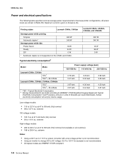
... electricity consumption will vary by device usage. Lexmark C544n, C544dn, C544dw, and C544dtn 500 W 340 W 18 W 36 W 0 W Typical electricity consumption2 Model Mode Power supply voltage (kwh) 100 V/50 Hz 115 V/60 Hz 230 V/50 Hz Lexmark C540n, C543dn TEC1 TEC1-Eco Mode 3.73 kwh 3.41...shown in Amperes (A). 5025-2xx, 4xx Power and electrical specifications The following table specified nominal average power requirements for example) is not recommended. • All duplex models are ENERGY STAR compliant. 1-6 Service Manual All power levels are in units of kilowatts per week...
... electricity consumption will vary by device usage. Lexmark C544n, C544dn, C544dw, and C544dtn 500 W 340 W 18 W 36 W 0 W Typical electricity consumption2 Model Mode Power supply voltage (kwh) 100 V/50 Hz 115 V/60 Hz 230 V/50 Hz Lexmark C540n, C543dn TEC1 TEC1-Eco Mode 3.73 kwh 3.41...shown in Amperes (A). 5025-2xx, 4xx Power and electrical specifications The following table specified nominal average power requirements for example) is not recommended. • All duplex models are ENERGY STAR compliant. 1-6 Service Manual All power levels are in units of kilowatts per week...
Service Manual
Page 33
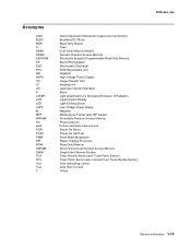
...Random Access Memory Electrically Erasable Programmable Read-Only Memory ElectroPhotographic Electrostatic Discharge Field Replaceable Unit Gigabyte High-Voltage Power Supply Image Transfer Unit Imaging Unit Japanese Industry Standard Black Light Amplification by Stimulated Emission of Radiation Liquid Crystal ...Display Light-Emitting Diode Low-Voltage Power Supply Magenta Multipurpose Feeder (also MP feeder) Nonvolatile Random Access Memory Photoconductor Picture elements (same as pel) Power-On Reset Power-On Self Test Pulse Width Modulation Raster Imaging Processor ...
...Random Access Memory Electrically Erasable Programmable Read-Only Memory ElectroPhotographic Electrostatic Discharge Field Replaceable Unit Gigabyte High-Voltage Power Supply Image Transfer Unit Imaging Unit Japanese Industry Standard Black Light Amplification by Stimulated Emission of Radiation Liquid Crystal ...Display Light-Emitting Diode Low-Voltage Power Supply Magenta Multipurpose Feeder (also MP feeder) Nonvolatile Random Access Memory Photoconductor Picture elements (same as pel) Power-On Reset Power-On Self Test Pulse Width Modulation Raster Imaging Processor ...
Service Manual
Page 37
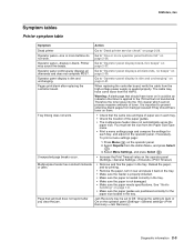
... cable from the Admin Menu, and press Select ( ). 3. The cable may sound five beeps. To print a menu settings page: 1. Select Reports from the high-voltage power supply is seated properly. Multipurpose feeder has constant misfeeds or jams. Page that toner is applied to Off. Operator panel-display is dim and unchanging. Change...
... cable from the Admin Menu, and press Select ( ). 3. The cable may sound five beeps. To print a menu settings page: 1. Select Reports from the high-voltage power supply is seated properly. Multipurpose feeder has constant misfeeds or jams. Page that toner is applied to Off. Operator panel-display is dim and unchanging. Change...
Service Manual
Page 53
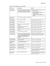
...xx-Printhead errors service check" on page 2-26. Go to "936.xx, 937.xx-Transport motor service check" on page 2-25. See "Low-voltage power supply (LVPS) assembly removal" on page 2-25. If this error message persists, replace the controller board. 5025-2xx, 4xx Service error messages (1xx, 9xx)...(TMC) switch error. Go to resolve this problem: • Use the base sensor test in the low-voltage (LV) power supply has failed, or the wrong lowvoltage power supply has been installed. The yellow cartridge toner meter cycle Go to "936.xx, 937.xx-Transport motor failure. The pel clock...
...xx-Printhead errors service check" on page 2-26. Go to "936.xx, 937.xx-Transport motor service check" on page 2-25. See "Low-voltage power supply (LVPS) assembly removal" on page 2-25. If this error message persists, replace the controller board. 5025-2xx, 4xx Service error messages (1xx, 9xx)...(TMC) switch error. Go to resolve this problem: • Use the base sensor test in the low-voltage (LV) power supply has failed, or the wrong lowvoltage power supply has been installed. The yellow cartridge toner meter cycle Go to "936.xx, 937.xx-Transport motor failure. The pel clock...

Service Manual
Page 62
... where you see this symbol, there is a danger from the printer. Unplug the product before you begin, or use caution if the product must receive power in the area of the fan or motors. Is the line voltage correct? 2 Is the AC line cord damaged? 3 Is the LVPS cable correctly... the printer by changes to step 5. 4 Turn the printer off, and then on the controller board? Replace the controller board. See "Low-voltage power supply (LVPS) assembly removal" on page 4-1. 5025-2xx, 4xx Dead printer service check A dead printer is one conductor at a time. Remove any input paper-handling ...
... where you see this symbol, there is a danger from the printer. Unplug the product before you begin, or use caution if the product must receive power in the area of the fan or motors. Is the line voltage correct? 2 Is the AC line cord damaged? 3 Is the LVPS cable correctly... the printer by changes to step 5. 4 Turn the printer off, and then on the controller board? Replace the controller board. See "Low-voltage power supply (LVPS) assembly removal" on page 4-1. 5025-2xx, 4xx Dead printer service check A dead printer is one conductor at a time. Remove any input paper-handling ...

Service Manual
Page 66
...pinch points, and the cable or connector for any other damage. Replace the fuser cable. Go to step 4. Step Questions / actions 1 Some low-voltage power supply FRUs have a voltage selector switch. Has the LVPS been changed? 2 Turn the printer off, and remove the rear shield. 5025-2xx, 4xx Step ...at JBIN1: JBIN1 Pin Value 4 +5 V dc 5 +0 V dc (no media), +3.3 V dc (media) 6 Ground Are the values correct? Is the cable damaged? 4 Check the power cable on the left side of the fuser and the thermistor cables and connections on the side of the fuser. Yes Check the switch on...
...pinch points, and the cable or connector for any other damage. Replace the fuser cable. Go to step 4. Step Questions / actions 1 Some low-voltage power supply FRUs have a voltage selector switch. Has the LVPS been changed? 2 Turn the printer off, and remove the rear shield. 5025-2xx, 4xx Step ...at JBIN1: JBIN1 Pin Value 4 +5 V dc 5 +0 V dc (no media), +3.3 V dc (media) 6 Ground Are the values correct? Is the cable damaged? 4 Check the power cable on the left side of the fuser and the thermistor cables and connections on the side of the fuser. Yes Check the switch on...
Service Manual
Page 77
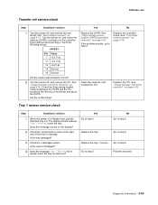
... Reset the value. To view the status of the photoconductor units: 1. It is not rough. Problem resolved. See "High-voltage power Problem resolved. Select Supplies Menu, and press Select ( ). 3. Does this fix the problem? 5 Check the high-voltage contact from the customer menus....photoconductor unit. See "Printhead removal" on page 4-33. • High-voltage power supply (HVPS). Some slick or coated papers may also cause the problem. Go to step 5. Using non-Lexmark toner cartridges may also cause background problems. Some problems occur by using rough paper...
... Reset the value. To view the status of the photoconductor units: 1. It is not rough. Problem resolved. See "High-voltage power Problem resolved. Select Supplies Menu, and press Select ( ). 3. Does this fix the problem? 5 Check the high-voltage contact from the customer menus....photoconductor unit. See "Printhead removal" on page 4-33. • High-voltage power supply (HVPS). Some slick or coated papers may also cause the problem. Go to step 5. Using non-Lexmark toner cartridges may also cause background problems. Some problems occur by using rough paper...
Service Manual
Page 79
... Diagnostics Menu. (Turn the printer off , and remove the rear shield. Replace the highvoltage power supply as necessary. See "High-voltage power supply (HVPS) assembly removal" on page 4-31. Diagnostic information 2-45 Did this fix the problem? See "High-voltage power supply (HVPS) assembly removal" on page 4-31. Resetting appears. Reseat the imaging unit. Go to...
... Diagnostics Menu. (Turn the printer off , and remove the rear shield. Replace the highvoltage power supply as necessary. See "High-voltage power supply (HVPS) assembly removal" on page 4-31. Diagnostic information 2-45 Did this fix the problem? See "High-voltage power supply (HVPS) assembly removal" on page 4-31. Resetting appears. Reseat the imaging unit. Go to...
Service Manual
Page 81
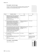
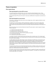
... the cables and connection correct? 3 Is the fuser properly installed? 4 Replace the fuser. Problem resolved. If the problem persists, replace the developer. See "Low-voltage power supply (LVPS) assembly removal" on page 4-26. Print quality-missing image at edge Remove and reseat the following: • Toner cartridge • Imaging unit • Developer...
... the cables and connection correct? 3 Is the fuser properly installed? 4 Replace the fuser. Problem resolved. If the problem persists, replace the developer. See "Low-voltage power supply (LVPS) assembly removal" on page 4-26. Print quality-missing image at edge Remove and reseat the following: • Toner cartridge • Imaging unit • Developer...
Service Manual
Page 84
... the continuity of paper over the gap between the developers. Replace the printhead. Replace the controller board. Does this solve the problem? See "High-voltage power supply (HVPS) assembly removal" on page 4-50. Go to step 5. Go to the photoconductor charge roll. Print quality-vertical banding Replace the developer unit. 2-50 Service...
... the continuity of paper over the gap between the developers. Replace the printhead. Replace the controller board. Does this solve the problem? See "High-voltage power supply (HVPS) assembly removal" on page 4-50. Go to step 5. Go to the photoconductor charge roll. Print quality-vertical banding Replace the developer unit. 2-50 Service...
Service Manual
Page 87
... sensor dislodged? 4 Does the message Tray 1 Missing fail to appear when the tray is in Ready state, pull the standard tray out. See "High-voltage power supply (HVPS) assembly removal" on page 4-19. 2 Turn the printer off , and remove the rear shield. Check the three spring-loaded contacts between the HVPS and...
... sensor dislodged? 4 Does the message Tray 1 Missing fail to appear when the tray is in Ready state, pull the standard tray out. See "High-voltage power supply (HVPS) assembly removal" on page 4-19. 2 Turn the printer off , and remove the rear shield. Check the three spring-loaded contacts between the HVPS and...
Service Manual
Page 123
... belt on the photoconductors and alters the surface charge relative to the planned image for each photoconductor. Expose the photoconductor (PC unit) 3. The high-voltage power supply sends charge to the transfer belt the photoconductors are applied to the page to permanently bond the toner to the media in the EP process...
... belt on the photoconductors and alters the surface charge relative to the planned image for each photoconductor. Expose the photoconductor (PC unit) 3. The high-voltage power supply sends charge to the transfer belt the photoconductors are applied to the page to permanently bond the toner to the media in the EP process...
Service Manual
Page 124
...% of each of toner will cause the charge to be deposited on the photoconductor. Check the repeating marks table that prints from the high-voltage power supply to be uneven on the printed page. This will need to the charge roll inside each color. The imaging unit will cause a repeating mark on...
...% of each of toner will cause the charge to be deposited on the photoconductor. Check the repeating marks table that prints from the high-voltage power supply to be uneven on the printed page. This will need to the charge roll inside each color. The imaging unit will cause a repeating mark on...

Service Manual
Page 126
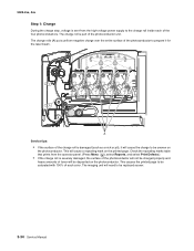
... can and then rolling it applies toner to the developer roll (C). 5025-2xx, 4xx Step 3: Develop Once the laser exposes the photoconductor, the high-voltage power supply sends charge to the surface. For each color, the toner cartridge engages the photoconductor so it over glitter. This process would be repeating marks, thin...
... can and then rolling it applies toner to the developer roll (C). 5025-2xx, 4xx Step 3: Develop Once the laser exposes the photoconductor, the high-voltage power supply sends charge to the surface. For each color, the toner cartridge engages the photoconductor so it over glitter. This process would be repeating marks, thin...
Service Manual
Page 127
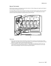
... toner will produce a void or light blotch on a page. The result would be repeating blotches of the ITU belt for each photoconductor, the high-voltage power supply sends voltage to be replaced. • Don't use solvents or other cleaners to -surface contact between the developed toner image on the photoconductor surface and...
... toner will produce a void or light blotch on a page. The result would be repeating blotches of the ITU belt for each photoconductor, the high-voltage power supply sends voltage to be replaced. • Don't use solvents or other cleaners to -surface contact between the developed toner image on the photoconductor surface and...


