Service Manual
Page 33
... by Stimulated Emission of Radiation Liquid Crystal Display Light-Emitting Diode Low-Voltage Power Supply Magenta Multipurpose Feeder (also MP feeder) Nonvolatile Random Access Memory Photoconductor Picture elements (same as pel) Power-On Reset Power-On Self Test Pulse Width Modulation Raster Imaging Processor Read Only Memory Synchronous Dual Random Access...
... by Stimulated Emission of Radiation Liquid Crystal Display Light-Emitting Diode Low-Voltage Power Supply Magenta Multipurpose Feeder (also MP feeder) Nonvolatile Random Access Memory Photoconductor Picture elements (same as pel) Power-On Reset Power-On Self Test Pulse Width Modulation Raster Imaging Processor Read Only Memory Synchronous Dual Random Access...
Service Manual
Page 41
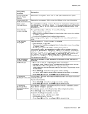
...paper. • Check tray length and width guides to ensure paper is too full to Memory to store pages is properly fitted in the new photoconductor unit. 32.xx Unsupported Cartridge Remove the specified cartridge, replace with a new one of the following : • Press Select ( ) to ... • Press Stop ( ), and then press Select ( ) to ensure the cartridge is defective. If the indicator says OK, replace only the photoconductor unit. Unsupported USB Remove the unrecognized USB hub from the original unit and reinstall them in the tray. • Adjust the Paper Size setting for...
...paper. • Check tray length and width guides to ensure paper is too full to Memory to store pages is properly fitted in the new photoconductor unit. 32.xx Unsupported Cartridge Remove the specified cartridge, replace with a new one of the following : • Press Select ( ) to ... • Press Stop ( ), and then press Select ( ) to ensure the cartridge is defective. If the indicator says OK, replace only the photoconductor unit. Unsupported USB Remove the unrecognized USB hub from the original unit and reinstall them in the tray. • Adjust the Paper Size setting for...
Service Manual
Page 76
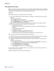
... the printer. Color Correction: Set to 4 (default). - 5025-2xx, 4xx Print quality service check Note: This symptom may need to install a developer (toner) cartridge or photoconductor unit. With the customer's permission, you may require replacement of one or more CRUs (Customer Replaceable Units) designated as supplies or maintenance items, which are...
... the printer. Color Correction: Set to 4 (default). - 5025-2xx, 4xx Print quality service check Note: This symptom may need to install a developer (toner) cartridge or photoconductor unit. With the customer's permission, you may require replacement of one or more CRUs (Customer Replaceable Units) designated as supplies or maintenance items, which are...
Service Manual
Page 77
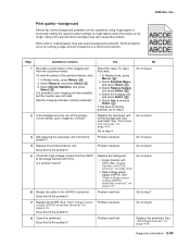
...in the JHVPS1 connector. To reset this fix the problem? Select Supplies Menu, and press Select ( ). 3. Go to step 4. 4 Replace the photoconductor unit. Go to step 7. 7 Replace the HVPS. Go to step 5. Problem resolved. Some slick or coated papers may also cause the problem. .... See "High-voltage power supply (HVPS) assembly removal" on page 4-33. • High-voltage power supply (HVPS). Using non-Lexmark toner cartridges may also cause background problems. Some problems occur by using rough paper or incorrectly setting the operator panel settings to step 2. ...
...in the JHVPS1 connector. To reset this fix the problem? Select Supplies Menu, and press Select ( ). 3. Go to step 4. 4 Replace the photoconductor unit. Go to step 7. 7 Replace the HVPS. Go to step 5. Problem resolved. Some slick or coated papers may also cause the problem. .... See "High-voltage power supply (HVPS) assembly removal" on page 4-33. • High-voltage power supply (HVPS). Using non-Lexmark toner cartridges may also cause background problems. Some problems occur by using rough paper or incorrectly setting the operator panel settings to step 2. ...
Service Manual
Page 80
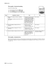
... the fuser. Replace the ITU. Go to step 4. See "Developer unit removal" on page 4-35. Is the distance between repeating bands. Replace the photoconductor unit. Go to step 2. 2 Does the distance measure 95 mm or 108 mm? Step Questions / actions Yes No 1 Measure the distance between bands....5 mm? 4 Does the distance measure 43.9 mm or 45.5? See "Fuser assembly removal" on page 4-26. Print quality-horizontal line Either the photoconductor unit or one of the imaging unit. Select Reports, and press Select ( ). 3. Check the various rollers in the printer for debris. At the...
... the fuser. Replace the ITU. Go to step 4. See "Developer unit removal" on page 4-35. Is the distance between repeating bands. Replace the photoconductor unit. Go to step 2. 2 Does the distance measure 95 mm or 108 mm? Step Questions / actions Yes No 1 Measure the distance between bands....5 mm? 4 Does the distance measure 43.9 mm or 45.5? See "Fuser assembly removal" on page 4-26. Print quality-horizontal line Either the photoconductor unit or one of the imaging unit. Select Reports, and press Select ( ). 3. Check the various rollers in the printer for debris. At the...
Service Manual
Page 82
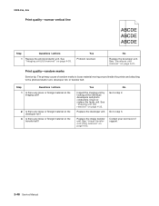
... unit (IU) removal" on page 4-35. Contact your next level of random marks is loose material moving around inside the printer and attaching to the photoconductor unit, developer roll, or transfer belt. Go to step 2. No Go to step 3. See "Imaging unit (IU) removal" on page 4-35. Yes Problem resolved. Replace... support. 2-48 Service Manual No Replace the developer unit. 5025-2xx, 4xx Print quality-narrow vertical line ABCDE ABCDE ABCDE Step Questions / actions 1 Replace the photoconductor unit. Replace the developer unit.
... unit (IU) removal" on page 4-35. Contact your next level of random marks is loose material moving around inside the printer and attaching to the photoconductor unit, developer roll, or transfer belt. Go to step 2. No Go to step 3. See "Imaging unit (IU) removal" on page 4-35. Yes Problem resolved. Replace... support. 2-48 Service Manual No Replace the developer unit. 5025-2xx, 4xx Print quality-narrow vertical line ABCDE ABCDE ABCDE Step Questions / actions 1 Replace the photoconductor unit. Replace the developer unit.

Service Manual
Page 83
... Replace the fuser. Diagnostic information 2-49 Does the display indicate OK? Is the distance 43.9 mm? Replace the imaging unit or the photoconductor unit. Press Menu ( ) on the fuser assembly? Contact your next level of the image. Select Supplies Menu, and press Select ...( ). 3. Replace the developer corresponding to step 2. 1. Replace the photoconductor. Print quality-residual image 5025-2xx, 4xx ABCDE ABCDE ABCDE Step Questions / actions Yes No 1 Check the condition of the imaging unit ...
... Replace the fuser. Diagnostic information 2-49 Does the display indicate OK? Is the distance 43.9 mm? Replace the imaging unit or the photoconductor unit. Press Menu ( ) on the fuser assembly? Contact your next level of the image. Select Supplies Menu, and press Select ...( ). 3. Replace the developer corresponding to step 2. 1. Replace the photoconductor. Print quality-residual image 5025-2xx, 4xx ABCDE ABCDE ABCDE Step Questions / actions Yes No 1 Check the condition of the imaging unit ...
Service Manual
Page 84
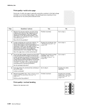
... can cause the problem. Replace the cable assembly. This will block the laser from the HVPS to the photoconductor charge roll. See "Toner cartridge contacts" on the entire photoconductor drum. 5025-2xx, 4xx Print quality-solid color page Service tip: A solid color page is making good... contact with the HPVS spring that runs through the left printer frame. Step Questions / actions Yes No 1 Replace the photoconductor unit (part of the imaging unit). Remove the imaging unit and remove the developers. See "Imaging unit (IU) removal". Is there continuity...
... can cause the problem. Replace the cable assembly. This will block the laser from the HVPS to the photoconductor charge roll. See "Toner cartridge contacts" on the entire photoconductor drum. 5025-2xx, 4xx Print quality-solid color page Service tip: A solid color page is making good... contact with the HPVS spring that runs through the left printer frame. Step Questions / actions Yes No 1 Replace the photoconductor unit (part of the imaging unit). Remove the imaging unit and remove the developers. See "Imaging unit (IU) removal". Is there continuity...
Service Manual
Page 123
...from the tray and carried to the transfer roll where the image is the same for every laser and LED printer, the specifics for each photoconductor. The fuser rollers push the media into the output bin. Even though the basic EP process is transferred from the toner cartridge to the printed... to the media. The media is carried to print is the command center for the next page. Develop the toner on the surface of each photoconductor. The controller board is called a photodeveloper cartridge or PC unit) and an image transfer unit (ITU). These machines use to the fuser rollers where ...
...from the tray and carried to the transfer roll where the image is the same for every laser and LED printer, the specifics for each photoconductor. The fuser rollers push the media into the output bin. Even though the basic EP process is transferred from the toner cartridge to the printed... to the media. The media is carried to print is the command center for the next page. Develop the toner on the surface of each photoconductor. The controller board is called a photodeveloper cartridge or PC unit) and an image transfer unit (ITU). These machines use to the fuser rollers where ...
Service Manual
Page 124
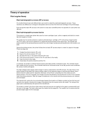
... unit will cause a repeating mark on the printed page. The charge roll is part of each of the four photoconductors. This causes the printed page to be uneven on the photoconductor. This will need to the charge roll inside each color. 5025-2xx, 4xx Step 1: Charge During the charge ... and select Print Defects.) • If the charge roll is severely damaged, the surface of the photoconductor will not be charged properly and heavy amounts of toner will be deposited on the photoconductor. Check the repeating marks table that prints from the high-voltage power supply to be replaced sooner....
... unit will cause a repeating mark on the printed page. The charge roll is part of each of the four photoconductors. This causes the printed page to be uneven on the photoconductor. This will need to the charge roll inside each color. 5025-2xx, 4xx Step 1: Charge During the charge ... and select Print Defects.) • If the charge roll is severely damaged, the surface of the photoconductor will not be charged properly and heavy amounts of toner will be deposited on the photoconductor. Check the repeating marks table that prints from the high-voltage power supply to be replaced sooner....
Service Manual
Page 125
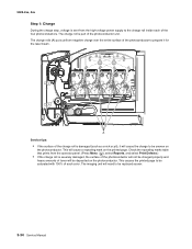
..."burn" it will cause white or light vertical streaks on the surface and toner will not stick properly. If exposed to light for each photoconductor (B) and writes an invisible image called a latent image or electrostatic image for too long, it will cause light/dark print quality problems and ...have to be replaced. • The surface of the photoconductor is coated with an organic substance that makes it exits the laser unit. The result would be replaced. The laser beam actually discharges the...
..."burn" it will cause white or light vertical streaks on the surface and toner will not stick properly. If exposed to light for each photoconductor (B) and writes an invisible image called a latent image or electrostatic image for too long, it will cause light/dark print quality problems and ...have to be replaced. • The surface of the photoconductor is coated with an organic substance that makes it exits the laser unit. The result would be replaced. The laser beam actually discharges the...

Service Manual
Page 126
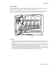
... cartridge will only stick where the laser exposed the surface. Check the surface of the photoconductor properly. The toner will have to the PC. 5025-2xx, 4xx Step 3: Develop Once the laser exposes the photoconductor, the high-voltage power supply sends charge to the surface. The oil from your bare... hand. For each color, the toner cartridge engages the photoconductor so it over glitter. This process would be similar to using glue to the rest of the developer roller with your skin may cause a...
... cartridge will only stick where the laser exposed the surface. Check the surface of the photoconductor properly. The toner will have to the PC. 5025-2xx, 4xx Step 3: Develop Once the laser exposes the photoconductor, the high-voltage power supply sends charge to the surface. The oil from your bare... hand. For each color, the toner cartridge engages the photoconductor so it over glitter. This process would be similar to using glue to the rest of the developer roller with your skin may cause a...
Service Manual
Page 127
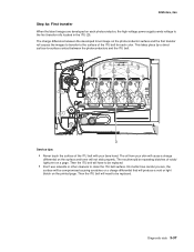
...a charge differential that will need to be replaced. • Don't use solvents or other cleaners to the surface of the ITU belt for each photoconductor, the high-voltage power supply sends voltage to the first transfer rolls located in the ITU (D). Then the ITU belt will produce a void or ...first transfer roll causes the images to transfer to clean the ITU belt surface. The oil from your bare hand. The charge difference between the photoconductors and the ITU belt. Diagnostic aids 3-37 Then the ITU belt will not stick properly. No matter how careful you are developed on the...
...a charge differential that will need to be replaced. • Don't use solvents or other cleaners to the surface of the ITU belt for each photoconductor, the high-voltage power supply sends voltage to the first transfer rolls located in the ITU (D). Then the ITU belt will produce a void or ...first transfer roll causes the images to transfer to clean the ITU belt surface. The oil from your bare hand. The charge difference between the photoconductors and the ITU belt. Diagnostic aids 3-37 Then the ITU belt will not stick properly. No matter how careful you are developed on the...
Service Manual
Page 128
... due to the media. Based on the speed of the transfer belt, the proper time to send the signal to the transfer belt from the photoconductors, the image is carried towards the transfer roll (E). the entire page will cause voids or lights spots on the transfer belt reaches the transfer roll...
... due to the media. Based on the speed of the transfer belt, the proper time to send the signal to the transfer belt from the photoconductors, the image is carried towards the transfer roll (E). the entire page will cause voids or lights spots on the transfer belt reaches the transfer roll...

Service Manual
Page 130
This occurs for every page that take place during the EP process. After the toner is moved to the cleaning blade, the toner is printed. Transfer unit clean Once the toner image on the transfer belt has been transferred to the page, the transfer belt rotates around and is cleaned by the cleaning blade (G). 5025-2xx, 4xx Step 6: Clean/erase There are two main cleaning processes that is moved from the cleaning blade to the waste toner area using an auger system. 3-40 Service Manual One process cleans the transfer belt and the other cleans the photoconductors.
This occurs for every page that take place during the EP process. After the toner is moved to the cleaning blade, the toner is printed. Transfer unit clean Once the toner image on the transfer belt has been transferred to the page, the transfer belt rotates around and is cleaned by the cleaning blade (G). 5025-2xx, 4xx Step 6: Clean/erase There are two main cleaning processes that is moved from the cleaning blade to the waste toner area using an auger system. 3-40 Service Manual One process cleans the transfer belt and the other cleans the photoconductors.

Service Manual
Page 131
Diagnostic aids 3-41 This cleaning/erasing cycle happens after each plane of color is transferred to the transfer belt from the photoconductors, a cleaning blade (H) scrapes the left over toner from the surface of each plane of color has been transferred to the transfer belt. 5025-2xx, 4xx Photoconductor clean/erase After each photoconductor. This is prepared to begin the EP cycle once again. Now the photoconductor surface is the clean/erase process.
Diagnostic aids 3-41 This cleaning/erasing cycle happens after each plane of color is transferred to the transfer belt from the photoconductors, a cleaning blade (H) scrapes the left over toner from the surface of each plane of color has been transferred to the transfer belt. 5025-2xx, 4xx Photoconductor clean/erase After each photoconductor. This is prepared to begin the EP cycle once again. Now the photoconductor surface is the clean/erase process.

Service Manual
Page 173
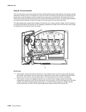
.... 5. Open the front cover. 2. Remove the toner cartridges. 6. When you replace the imaging kit, you are replacing both the photoconductor and the developer units. 1. See "Waste toner bottle removal" on page 4-10. 4. Note: The imaging unit contains: •...; Photoconductor unit • Developer units To remove only the photoconductor, remove the entire imaging unit, remove the developer units, place the original developer units in the new photoconductor, and re-install the imaging unit. Remove the right cover assembly.
.... 5. Open the front cover. 2. Remove the toner cartridges. 6. When you replace the imaging kit, you are replacing both the photoconductor and the developer units. 1. See "Waste toner bottle removal" on page 4-10. 4. Note: The imaging unit contains: •...; Photoconductor unit • Developer units To remove only the photoconductor, remove the entire imaging unit, remove the developer units, place the original developer units in the new photoconductor, and re-install the imaging unit. Remove the right cover assembly.
Service Manual
Page 231
... pick motor assembly see autocompensator mechanism (ACM) 4-15 parts catalog cables 7-8 covers 7-2 electronics 7-6 frames 7-4 options and miscellaneous 7-9 password, panel menus 3-25 Perm Page Count 3-17 photoconductor unit description 4-35 imaging kit 4-35 pick tires parts catalog 7-2, 7-9 removal 4-48 pogo pin see toner cartridge contacts POR sequence 2-2 power-on sequence (POR) 2-2 PPDS...
... pick motor assembly see autocompensator mechanism (ACM) 4-15 parts catalog cables 7-8 covers 7-2 electronics 7-6 frames 7-4 options and miscellaneous 7-9 password, panel menus 3-25 Perm Page Count 3-17 photoconductor unit description 4-35 imaging kit 4-35 pick tires parts catalog 7-2, 7-9 removal 4-48 pogo pin see toner cartridge contacts POR sequence 2-2 power-on sequence (POR) 2-2 PPDS...
Service Manual
Page 232
...) 4-31 image transfer unit (ITU) 4-33 imaging unit (IU) 4-35 left lower frame 4-39 low-voltage power supply (LVPS) 4-37 main drive gear assembly 4-45 photoconductor unit 4-35 pick tires, 250-sheet media tray 4-48 printhead 4-49 right lower frame 4-41 toner cartridge contacts 4-50 toner density sensor (TDS), left and...
...) 4-31 image transfer unit (ITU) 4-33 imaging unit (IU) 4-35 left lower frame 4-39 low-voltage power supply (LVPS) 4-37 main drive gear assembly 4-45 photoconductor unit 4-35 pick tires, 250-sheet media tray 4-48 printhead 4-49 right lower frame 4-41 toner cartridge contacts 4-50 toner density sensor (TDS), left and...


