Service Manual
Page 20
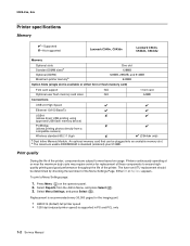
... (reduced printer speed) is standard (soldered) plus 512MB. The fuser and ITU replacement should be plugged into an available memory slot. Press Menu ( ) on usage. Replacement is recommended every 30,000 pages for replacement of these components to wear based on the operator panel. 2. ... by checking the last sheet of the printer. 5025-2xx, 4xx Printer specifications Memory ✔-Supported ✘-Not supported Lexmark C540n, C543dn Lexmark C544n, C544dn, C544dw Memory Optional slots Standard DIMM sizesa Optional (DDR2) Maximum printer memoryb One slot 128MB 128MB, 256MB...
... (reduced printer speed) is standard (soldered) plus 512MB. The fuser and ITU replacement should be plugged into an available memory slot. Press Menu ( ) on usage. Replacement is recommended every 30,000 pages for replacement of these components to wear based on the operator panel. 2. ... by checking the last sheet of the printer. 5025-2xx, 4xx Printer specifications Memory ✔-Supported ✘-Not supported Lexmark C540n, C543dn Lexmark C544n, C544dn, C544dw Memory Optional slots Standard DIMM sizesa Optional (DDR2) Maximum printer memoryb One slot 128MB 128MB, 256MB...
Service Manual
Page 53
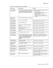
...xx-Printhead errors service check" on page 2-25. The cyan cartridge toner meter cycle (TMC) switch error. TMC card" on page 2-52. Replace the low-voltage power supply. The Servicer should follow these steps to resolve this problem: • Use the base sensor test in the low-...inspect the toner sensor's operation. • If the toner sensor is operating correctly, then the problem is locked. service check" on the toner sensor for fuser control in Diagnostics Menu to "Toner meter sensors (Y, C, M, K) on TMC card" on page 2-52. The zero crossing signal used for a set ...
...xx-Printhead errors service check" on page 2-25. The cyan cartridge toner meter cycle (TMC) switch error. TMC card" on page 2-52. Replace the low-voltage power supply. The Servicer should follow these steps to resolve this problem: • Use the base sensor test in the low-...inspect the toner sensor's operation. • If the toner sensor is operating correctly, then the problem is locked. service check" on the toner sensor for fuser control in Diagnostics Menu to "Toner meter sensors (Y, C, M, K) on TMC card" on page 2-52. The zero crossing signal used for a set ...
Service Manual
Page 58
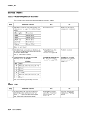
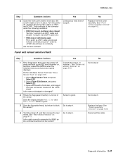
...No 1 Check the clearance around the printer. Does the error clear? 2 Check the fuser connections on the fuser, at JFUSES1 on , and then check the following values at the LVPS. Replace the fuser. Problem resolved. Check the cable connections. See "Controller board removal" on page 1-5 or... and +3.28 V dc 6 Ground 8 Ground 9 +3.3 V dc 10 Between +0.6 V dc and +3.15 V dc 11 Ground Are these values approximately correct? Replace the fuser assembly. See "Fuser assembly removal" on page 4-19. 90x.xx error Step Questions / actions 1 Turn the printer off, and remove the rear shield...
...No 1 Check the clearance around the printer. Does the error clear? 2 Check the fuser connections on the fuser, at JFUSES1 on , and then check the following values at the LVPS. Replace the fuser. Problem resolved. Check the cable connections. See "Controller board removal" on page 1-5 or... and +3.28 V dc 6 Ground 8 Ground 9 +3.3 V dc 10 Between +0.6 V dc and +3.15 V dc 11 Ground Are these values approximately correct? Replace the fuser assembly. See "Fuser assembly removal" on page 4-19. 90x.xx error Step Questions / actions 1 Turn the printer off, and remove the rear shield...
Service Manual
Page 65
... sensor located on page 4-26. Are the tests verified? Is the sensor dislodged or damaged? No Go to step 5. Replace the fuser. Reconnect the cable. Go to step 3. Perform the Base Sensor Test. Sensor is in and out of sure the right cover is good. Go to...at JINT1 cable end should have no continuity. See "Rear shield removal" on page 4-2. Correct the sensor, or replace it. Turn the printer support. Be Contact your next level of the sensor. See "Fuser exit sensor removal" on the controller board and to block the sensor? Is the cable correctly connected to...
... sensor located on page 4-26. Are the tests verified? Is the sensor dislodged or damaged? No Go to step 5. Replace the fuser. Reconnect the cable. Go to step 3. Perform the Base Sensor Test. Sensor is in and out of sure the right cover is good. Go to...at JINT1 cable end should have no continuity. See "Rear shield removal" on page 4-2. Correct the sensor, or replace it. Turn the printer support. Be Contact your next level of the sensor. See "Fuser exit sensor removal" on the controller board and to block the sensor? Is the cable correctly connected to...

Service Manual
Page 66
... actions 1 Some low-voltage power supply FRUs have a voltage selector switch. Yes Check the switch on page 4-30. Replace the fuser cable. Repair the cables. Fuser service check No Replace the controller board. See "Controller board removal" on page 4-11. See "Rear shield removal" on page 4-19. ... LVPS cable. Go to step 2. 5025-2xx, 4xx Step Questions / actions Yes 5 Turn the printer on the right side of the fuser. Replace the fuser exit sensor. Check the cable at JBIN1: JBIN1 Pin Value 4 +5 V dc 5 +0 V dc (no media), +3.3 V dc (media) 6 Ground Are the values ...
... actions 1 Some low-voltage power supply FRUs have a voltage selector switch. Yes Check the switch on page 4-30. Replace the fuser cable. Repair the cables. Fuser service check No Replace the controller board. See "Controller board removal" on page 4-11. See "Rear shield removal" on page 4-19. ... LVPS cable. Go to step 2. 5025-2xx, 4xx Step Questions / actions Yes 5 Turn the printer on the right side of the fuser. Replace the fuser exit sensor. Check the cable at JBIN1: JBIN1 Pin Value 4 +5 V dc 5 +0 V dc (no media), +3.3 V dc (media) 6 Ground Are the values ...

Service Manual
Page 67
See "Controller board removal" on page 4-19. See "Controller board removal" on page 4-19. Replace the controller board. Problem resolved. 5025-2xx, 4xx No Replace the controller board. Diagnostic information 2-33 See "Fuser assembly removal" on page 4-26. Does the error clear? Step Questions / actions 5 Check the following values at JFUSES1: JFUSES1 Pin Value 5 +3.3 V dc 6 Ground 8 Ground 10 +2.7 V dc 11 Ground Are the values approximately correct? 6 Replace the fuser. Yes Go to step 6.
See "Controller board removal" on page 4-19. See "Controller board removal" on page 4-19. Replace the controller board. Problem resolved. 5025-2xx, 4xx No Replace the controller board. Diagnostic information 2-33 See "Fuser assembly removal" on page 4-26. Does the error clear? Step Questions / actions 5 Check the following values at JFUSES1: JFUSES1 Pin Value 5 +3.3 V dc 6 Ground 8 Ground 10 +2.7 V dc 11 Ground Are the values approximately correct? 6 Replace the fuser. Yes Go to step 6.
Service Manual
Page 80
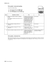
... match the missing color (black, cyan, magenta, or yellow). Go to step 2. 2 Does the distance measure 95 mm or 108 mm? Replace the fuser. Replace the ITU. Select Reports, and press Select ( ). 3. Replace the developers that make up the imaging unit is defective. Remove and inspect the imaging unit. Is the distance between repeating...
... match the missing color (black, cyan, magenta, or yellow). Go to step 2. 2 Does the distance measure 95 mm or 108 mm? Replace the fuser. Replace the ITU. Select Reports, and press Select ( ). 3. Replace the developers that make up the imaging unit is defective. Remove and inspect the imaging unit. Is the distance between repeating...
Service Manual
Page 81
...Imaging unit • Developer units. Diagnostic information 2-47 Problem resolved. If the problem persists, replace the developer. See "Fuser assembly removal" on page 4-37. Go to indicate the correct media. Replace the LVPS. No Change the settings to step 4. Are the cables and connection correct? 3... Is the fuser properly installed? 4 Replace the fuser. Yes Go to step 2. 2 Check the fuser connections on the left and right side of ...
...Imaging unit • Developer units. Diagnostic information 2-47 Problem resolved. If the problem persists, replace the developer. See "Fuser assembly removal" on page 4-37. Go to indicate the correct media. Replace the LVPS. No Change the settings to step 4. Are the cables and connection correct? 3... Is the fuser properly installed? 4 Replace the fuser. Yes Go to step 2. 2 Check the fuser connections on the left and right side of ...

Service Manual
Page 83
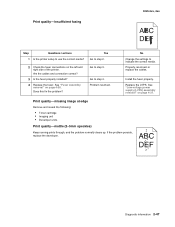
...Menu Setting Page twice to the same point on the fuser assembly? Press Menu ( ) on page 4-26. Contact your next level of the image. Replace the developer corresponding to step 2. 1. To print a menu settings page: 1. Replace the imaging unit or the photoconductor unit. Is the distance... 43.9 mm? Select Reports from the original image to clear any toner contamination on the residual image. Replace the fuser. Select Imaging Kit, and press Select ( ). Does the display indicate OK? Print quality-residual image 5025-2xx, 4xx ABCDE...
...Menu Setting Page twice to the same point on the fuser assembly? Press Menu ( ) on page 4-26. Contact your next level of the image. Replace the developer corresponding to step 2. 1. To print a menu settings page: 1. Replace the imaging unit or the photoconductor unit. Is the distance... 43.9 mm? Select Reports from the original image to clear any toner contamination on the residual image. Replace the fuser. Select Imaging Kit, and press Select ( ). Does the display indicate OK? Print quality-residual image 5025-2xx, 4xx ABCDE...

Service Manual
Page 106
... Closed Opened/ Closed Opened/ Closed Opened/ Closed How to test, and press Select ( ). The sensor should change state. Activate the fuser exit flag. Shine a flashlight on the toner level sensor. Remove the black toner cartridge. Miscellaneous tests Motor Detect This test initiates an automatic... not press Select yet. 3. or Media present... Remove the media tray. The sensor should be performed whenever the controller board is replaced. Shine a flashlight on the toner level sensor. The motor detection process takes about 10 seconds, and stops automatically. Remove Cartridge. ...
... Closed Opened/ Closed Opened/ Closed Opened/ Closed How to test, and press Select ( ). The sensor should change state. Activate the fuser exit flag. Shine a flashlight on the toner level sensor. Remove the black toner cartridge. Miscellaneous tests Motor Detect This test initiates an automatic... not press Select yet. 3. or Media present... Remove the media tray. The sensor should be performed whenever the controller board is replaced. Shine a flashlight on the toner level sensor. The motor detection process takes about 10 seconds, and stops automatically. Remove Cartridge. ...
Service Manual
Page 109
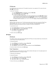
...changes... Select PRINTER SETUP from Diag Menu, and press Select ( ). 2. Reset Resetting... Sometimes this value. Select EP Setup from Diag Menu, and press Select ( ). 2. Select Fuser Temp, and press Select ( ). 3. Stop ( ) exits the menu. appears. Select Normal, High, or Low. Diagnostic aids 3-19 This setting appears only if the Maintenance Warning...records each printer setting listed in the printer. To cancel and return to the menus, press Back ( ). When the last number is entered and you replace the ITU, reenter this is used to its factory default value.
...changes... Select PRINTER SETUP from Diag Menu, and press Select ( ). 2. Reset Resetting... Sometimes this value. Select EP Setup from Diag Menu, and press Select ( ). 2. Select Fuser Temp, and press Select ( ). 3. Stop ( ) exits the menu. appears. Select Normal, High, or Low. Diagnostic aids 3-19 This setting appears only if the Maintenance Warning...records each printer setting listed in the printer. To cancel and return to the menus, press Back ( ). When the last number is entered and you replace the ITU, reenter this is used to its factory default value.

Service Manual
Page 129
Always check the paper type setting before replacing the fuser. Diagnostic aids 3-39 5025-2xx, 4xx Step 5: Fuse Once the image has been fully ...as card stock) with the paper type set to back the jammed page out of a malfunctioning fuser or an improper media setting. try to plain paper. • Never pull media with unfused toner up through the.... • Toner that rubs off a printed page can help it was traveling. The fuser moves the paper from the rollers and into the fuser area. The fuser (F) applies heat and pressure to the page to melt the tiny toner particles and bond ...
Always check the paper type setting before replacing the fuser. Diagnostic aids 3-39 5025-2xx, 4xx Step 5: Fuse Once the image has been fully ...as card stock) with the paper type set to back the jammed page out of a malfunctioning fuser or an improper media setting. try to plain paper. • Never pull media with unfused toner up through the.... • Toner that rubs off a printed page can help it was traveling. The fuser moves the paper from the rollers and into the fuser area. The fuser (F) applies heat and pressure to the page to melt the tiny toner particles and bond ...


