Hardware Maintenance Manual
Page 36
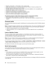
...8226; Missing parts might be downloaded from the Lenovo Support Web site. • The two programs are applicable to computers installed with the ThinkPad notebook computer. Note: The Lenovo Solution Center program is not installed with the Lenovo Soluton Center program, you are servicing is available... and resolve computer internal storage and memory problems. Notes: • If the computer you can download the quick test programs from http://www.lenovo.com/diags. Quick test programs Lenovo Hard Drive Quick Test and Lenovo Memory Quick Test are intended to test only ThinkPad products.
...8226; Missing parts might be downloaded from the Lenovo Support Web site. • The two programs are applicable to computers installed with the ThinkPad notebook computer. Note: The Lenovo Solution Center program is not installed with the Lenovo Soluton Center program, you are servicing is available... and resolve computer internal storage and memory problems. Notes: • If the computer you can download the quick test programs from http://www.lenovo.com/diags. Quick test programs Lenovo Hard Drive Quick Test and Lenovo Memory Quick Test are intended to test only ThinkPad products.
Hardware Maintenance Manual
Page 37
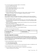
....exe file. 3. Follow the instructions on the main screen are as follows: Tests • Quick Memory Test • Quick Storage Device Test • Exit Application Tools • System Information • ...are servicing is displayed, go to start the test. If an error code is not installed with the UEFI diagnostic program, you can create a bootable diagnostic medium on page 32, ...is displayed, repeatedly press and release the F12 key. When the ThinkPad logo is displayed. 5. Attach the USB device to http://www.lenovo.com/diags. 2. Select the device class to create a bootable...
....exe file. 3. Follow the instructions on the main screen are as follows: Tests • Quick Memory Test • Quick Storage Device Test • Exit Application Tools • System Information • ...are servicing is displayed, go to start the test. If an error code is not installed with the UEFI diagnostic program, you can create a bootable diagnostic medium on page 32, ...is displayed, repeatedly press and release the F12 key. When the ThinkPad logo is displayed. 5. Attach the USB device to http://www.lenovo.com/diags. 2. Select the device class to create a bootable...
Hardware Maintenance Manual
Page 47
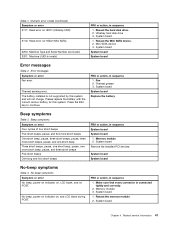
... Table 2. Please replace the battery with the correct Lenovo battery for this system and will not charge. Press the ESC key to continue. System board System board Replace the battery. System board Remove the installed PCI devices. FRU or action, in sequence 1....grease 3. FRU or action, in sequence System board System board 1. Reseat the Mini SATA device. 2. Thermal sensing error. Memory module 3. Mini SATA device 3. The battery installed is connected tightly and correctly. 2. System board System board No-beep symptoms Table 4. System board Chapter 4. Table 1. Numeric...
... Table 2. Please replace the battery with the correct Lenovo battery for this system and will not charge. Press the ESC key to continue. System board System board Replace the battery. System board Remove the installed PCI devices. FRU or action, in sequence 1....grease 3. FRU or action, in sequence System board System board 1. Reseat the Mini SATA device. 2. Thermal sensing error. Memory module 3. Mini SATA device 3. The battery installed is connected tightly and correctly. 2. System board System board No-beep symptoms Table 4. System board Chapter 4. Table 1. Numeric...
Hardware Maintenance Manual
Page 49
... Visually check each FRU for damage. Remove or disconnect all and then install only one at a time (do not replace a nondefective FRU): ..., replace the following devices: a. Replace any damaged FRU. 3. Battery pack e. PC Cards 4. System board b. Memory module (Remove all of the following FRUs one at a time until you find the failing FRU. 7. Turn on the... computer. 5. LCD assembly Chapter 4. Non-ThinkPad devices b. Related service information 43 Turn off the computer. 2. Devices attached to the docking station or...
... Visually check each FRU for damage. Remove or disconnect all and then install only one at a time (do not replace a nondefective FRU): ..., replace the following devices: a. Replace any damaged FRU. 3. Battery pack e. PC Cards 4. System board b. Memory module (Remove all of the following FRUs one at a time until you find the failing FRU. 7. Turn on the... computer. 5. LCD assembly Chapter 4. Non-ThinkPad devices b. Related service information 43 Turn off the computer. 2. Devices attached to the docking station or...
Hardware Maintenance Manual
Page 61
Installation of this Hardware Maintenance Manual. If you intend on product design might include the memory module, wireless card, keyboard, and palm rest with your product and are held by no more than two screws. See your Lenovo Limited Warranty documentation for the replacement CRU if Lenovo ... by more than two screws. ThinkPad computers contain the following types of CRUs include the ac power adapter, power cord, battery, and hard disk drive. Self-service CRUs: These CRUs unplug or are available from Lenovo at http://www.lenovo.com/support. An electronic version ...
Installation of this Hardware Maintenance Manual. If you intend on product design might include the memory module, wireless card, keyboard, and palm rest with your product and are held by no more than two screws. See your Lenovo Limited Warranty documentation for the replacement CRU if Lenovo ... by more than two screws. ThinkPad computers contain the following types of CRUs include the ac power adapter, power cord, battery, and hard disk drive. Self-service CRUs: These CRUs unplug or are available from Lenovo at http://www.lenovo.com/support. An electronic version ...
Hardware Maintenance Manual
Page 75
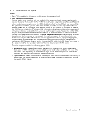
Chapter 10. Removing or replacing a FRU 69 Otherwise, the system might not function correctly. 1 2 1040 Memory module (bottom slot) For access, remove these FRUs in order: • "1010 Battery pack" on page 66 • "1030 Memory module slot cover" on page 68 Removal steps of memory module (bottom slot) Attention: For ThinkPad W530 models that come with two dummy cards installed, do not replace the dummy cards with memory modules.
Chapter 10. Removing or replacing a FRU 69 Otherwise, the system might not function correctly. 1 2 1040 Memory module (bottom slot) For access, remove these FRUs in order: • "1010 Battery pack" on page 66 • "1030 Memory module slot cover" on page 68 Removal steps of memory module (bottom slot) Attention: For ThinkPad W530 models that come with two dummy cards installed, do not replace the dummy cards with memory modules.

Hardware Maintenance Manual
Page 76
Make sure that it is firmly installed in suspend mode. The drive is in the slot and does not move easily. 1050 Hard disk drive or solid state drive For access, remove ... drive Note: Loosen the screw 1 , but do not remove it snaps into the slot. Press the memory module firmly, and pivot it until it . 70 Hardware Maintenance Manual 1 2 1 When installing: Insert the notched end of the memory module into place. Improper handling can cause damage and permanent loss of data. • Before removing...
Make sure that it is firmly installed in suspend mode. The drive is in the slot and does not move easily. 1050 Hard disk drive or solid state drive For access, remove ... drive Note: Loosen the screw 1 , but do not remove it snaps into the slot. Press the memory module firmly, and pivot it until it . 70 Hardware Maintenance Manual 1 2 1 When installing: Insert the notched end of the memory module into place. Improper handling can cause damage and permanent loss of data. • Before removing...
Hardware Maintenance Manual
Page 78
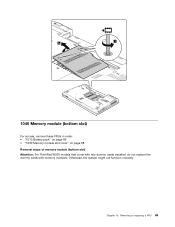
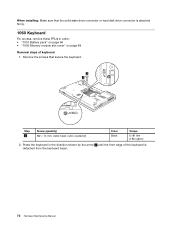
... the keyboard bezel. 72 Hardware Maintenance Manual Press the keyboard in order: • "1010 Battery pack" on page 66 • "1030 Memory module slot cover" on page 68 Removal steps of the keyboard is attached firmly. 1060 Keyboard For access, remove these FRUs in the direction ...shown by the arrow 2 until the front edge of keyboard 1. When installing: Make sure that secure the keyboard. 1 1 Step 1 Screw (quantity) M2 × 14 mm, wafer-head, nylon-coated (2) Color Black Torque 0....
... the keyboard bezel. 72 Hardware Maintenance Manual Press the keyboard in order: • "1010 Battery pack" on page 66 • "1030 Memory module slot cover" on page 68 Removal steps of the keyboard is attached firmly. 1060 Keyboard For access, remove these FRUs in the direction ...shown by the arrow 2 until the front edge of keyboard 1. When installing: Make sure that secure the keyboard. 1 1 Step 1 Screw (quantity) M2 × 14 mm, wafer-head, nylon-coated (2) Color Black Torque 0....
Hardware Maintenance Manual
Page 81
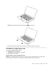
..." on page 66 • "1030 Memory module slot cover" on page 68 • "1060 Keyboard" on page 72 Removal steps of memory module (upper slot) Attention: For ThinkPad W530 models that the front side of the keyboard b is housed firmly. Note: Make sure that come with two dummy cards installed, do not replace the dummy...
..." on page 66 • "1030 Memory module slot cover" on page 68 • "1060 Keyboard" on page 72 Removal steps of memory module (upper slot) Attention: For ThinkPad W530 models that the front side of the keyboard b is housed firmly. Note: Make sure that come with two dummy cards installed, do not replace the dummy...
Hardware Maintenance Manual
Page 82
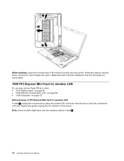
... it snaps into the socket. Note: Some models might have only two antenna cables in direction of the memory module into place. Press the memory module firmly, and pivot it until it is firmly installed in the slot and does not move easily. 1080 PCI Express Mini Card for wireless LAN For access..., remove these FRUs in order: • "1010 Battery pack" on page 66 • "1030 Memory module slot cover" on page 68 • "1060 Keyboard" on...
... it snaps into the socket. Note: Some models might have only two antenna cables in direction of the memory module into place. Press the memory module firmly, and pivot it until it is firmly installed in the slot and does not move easily. 1080 PCI Express Mini Card for wireless LAN For access..., remove these FRUs in order: • "1010 Battery pack" on page 66 • "1030 Memory module slot cover" on page 68 • "1060 Keyboard" on...
Hardware Maintenance Manual
Page 84
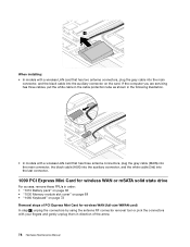
..., remove these FRUs in order: • "1010 Battery pack" on page 66 • "1030 Memory module slot cover" on page 68 • "1060 Keyboard" on page 72 Removal steps of the arrow. 78 Hardware Maintenance Manual When installing: • In models with a wireless LAN card that has three antenna connectors, plug the...
..., remove these FRUs in order: • "1010 Battery pack" on page 66 • "1030 Memory module slot cover" on page 68 • "1060 Keyboard" on page 72 Removal steps of the arrow. 78 Hardware Maintenance Manual When installing: • In models with a wireless LAN card that has three antenna connectors, plug the...
Hardware Maintenance Manual
Page 89
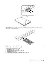
1 2 When installing: Make sure that the ExpressCard blank bezel or ExpressCard is correctly oriented as shown in the following illustration. 1110 Keyboard bezel assembly For access, remove these FRUs in order: • "1010 Battery pack" on page 66 • "1030 Memory module slot cover" on page 68 • "1060 Keyboard" on page 72 • "1100 ExpressCard blank bezel or ExpressCard" on page 82 Chapter 10. Removing or replacing a FRU 83
1 2 When installing: Make sure that the ExpressCard blank bezel or ExpressCard is correctly oriented as shown in the following illustration. 1110 Keyboard bezel assembly For access, remove these FRUs in order: • "1010 Battery pack" on page 66 • "1030 Memory module slot cover" on page 68 • "1060 Keyboard" on page 72 • "1100 ExpressCard blank bezel or ExpressCard" on page 82 Chapter 10. Removing or replacing a FRU 83
Hardware Maintenance Manual
Page 92
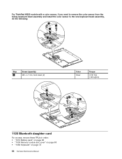
For ThinkPad W530 models with a color sensor, if you need to remove the color sensor from the failing keyboard bezel assembly and install the color sensor to the new keyboard bezel assembly, do the following: 3 3 4 1 2 Step 3 Screw (quantity) M2 × L7 mm, bind-head, (2) 1 Color Silver Torque 0.181 Nm (1.85 kgfcm) 4 4 3 2 1120 Bluetooth daughter card For access, remove these FRUs in order: • "1010 Battery pack" on page 66 • "1030 Memory module slot cover" on page 68 • "1060 Keyboard" on page 72 86 Hardware Maintenance Manual
For ThinkPad W530 models with a color sensor, if you need to remove the color sensor from the failing keyboard bezel assembly and install the color sensor to the new keyboard bezel assembly, do the following: 3 3 4 1 2 Step 3 Screw (quantity) M2 × L7 mm, bind-head, (2) 1 Color Silver Torque 0.181 Nm (1.85 kgfcm) 4 4 3 2 1120 Bluetooth daughter card For access, remove these FRUs in order: • "1010 Battery pack" on page 66 • "1030 Memory module slot cover" on page 68 • "1060 Keyboard" on page 72 86 Hardware Maintenance Manual
Hardware Maintenance Manual
Page 93
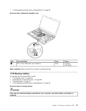
...of Bluetooth daughter card Step 1 Screw (quantity) M2 × 3 mm, wafer-head, nylon-coated (1) Color Silver Torque 0.181 Nm (1.85 kgfcm) When installing: Make sure that the connector is attached firmly. 1130 Backup battery For access, remove these FRUs in order: • "1010 Battery pack" on page 66... • "1030 Memory module slot cover" on page 68 • "1060 Keyboard" on page 72 • "1100 ExpressCard blank bezel or ExpressCard" on page 82 Removal ...
...of Bluetooth daughter card Step 1 Screw (quantity) M2 × 3 mm, wafer-head, nylon-coated (1) Color Silver Torque 0.181 Nm (1.85 kgfcm) When installing: Make sure that the connector is attached firmly. 1130 Backup battery For access, remove these FRUs in order: • "1010 Battery pack" on page 66... • "1030 Memory module slot cover" on page 68 • "1060 Keyboard" on page 72 • "1100 ExpressCard blank bezel or ExpressCard" on page 82 Removal ...
Hardware Maintenance Manual
Page 94
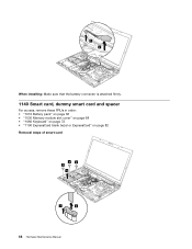
When installing: Make sure that the battery connector is attached firmly. 1140 Smart card, dummy smart card and spacer For access, remove these FRUs in order: • "1010 Battery pack" on page 66 • "1030 Memory module slot cover" on page 68 • "1060 Keyboard" on page 72 • "1100 ExpressCard blank bezel or ExpressCard" on page 82 Removal steps of smart card 33 3 4 1 2 88 Hardware Maintenance Manual
When installing: Make sure that the battery connector is attached firmly. 1140 Smart card, dummy smart card and spacer For access, remove these FRUs in order: • "1010 Battery pack" on page 66 • "1030 Memory module slot cover" on page 68 • "1060 Keyboard" on page 72 • "1100 ExpressCard blank bezel or ExpressCard" on page 82 Removal steps of smart card 33 3 4 1 2 88 Hardware Maintenance Manual

Hardware Maintenance Manual
Page 96
Removal steps of speaker assembly Step 1 Screw (quantity) M2 × 3 mm, wafer-head, nylon-coated (4) 5 5 5 5 4 4 Color Silver Torque 0.181 Nm (1.85 kgfcm) 5 4 4 When installing: Make sure that the speaker connector is attached firmly. Then route the cables and secure them properly as shown in the illustration above. 1160 Thermal fan assembly For access, remove these FRUs in order: • "1010 Battery pack" on page 66 • "1030 Memory module slot cover" on page 68 90 Hardware Maintenance Manual
Removal steps of speaker assembly Step 1 Screw (quantity) M2 × 3 mm, wafer-head, nylon-coated (4) 5 5 5 5 4 4 Color Silver Torque 0.181 Nm (1.85 kgfcm) 5 4 4 When installing: Make sure that the speaker connector is attached firmly. Then route the cables and secure them properly as shown in the illustration above. 1160 Thermal fan assembly For access, remove these FRUs in order: • "1010 Battery pack" on page 66 • "1030 Memory module slot cover" on page 68 90 Hardware Maintenance Manual
Hardware Maintenance Manual
Page 100
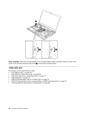
2 1 a When installing: Place the microprocessor in the microprocessor socket, and then rotate the head of the screw in the direction shown by the arrow a to secure the microprocessor. 1180 LCD unit For access, remove these FRUs in order: • "1010 Battery pack" on page 66 • "1030 Memory module slot cover" on page...
2 1 a When installing: Place the microprocessor in the microprocessor socket, and then rotate the head of the screw in the direction shown by the arrow a to secure the microprocessor. 1180 LCD unit For access, remove these FRUs in order: • "1010 Battery pack" on page 66 • "1030 Memory module slot cover" on page...
Hardware Maintenance Manual
Page 106
...sub card 1 2 1 Step 1 Screw (quantity) M2 × 7 mm, wafer-head, nylon-coated (2) Color Silver Torque 0.181 Nm (1.85 kgfcm) When installing: Make sure that the connector is installed on page 99. For access, remove these FRUs in order: • "1010 Battery pack" on page 66 • "1020 Serial Ultrabay Enhanced... device or blank bezel" on page 67 • "1030 Memory module slot cover" on page 68 • "1050 ...
...sub card 1 2 1 Step 1 Screw (quantity) M2 × 7 mm, wafer-head, nylon-coated (2) Color Silver Torque 0.181 Nm (1.85 kgfcm) When installing: Make sure that the connector is installed on page 99. For access, remove these FRUs in order: • "1010 Battery pack" on page 66 • "1020 Serial Ultrabay Enhanced... device or blank bezel" on page 67 • "1030 Memory module slot cover" on page 68 • "1050 ...
Hardware Maintenance Manual
Page 107
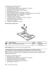
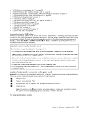
...soldered on a padded surface such as an ESD mat or conductive corrugated material. • "1070 Memory module (upper slot)" on page 75 • "1080 PCI Express Mini Card for wireless LAN"...for RAID setting: Before you replace the system board, ensure that you have read Chapter 5 "Installing and configuring RAID" on page 45, and have this chip. Then, you will see that ...d is enabled. For Integrated Graphics models: Chapter 10. To verify the RAID mode setting, check the ThinkPad Setup setting by selecting Config ➙ Serial ATA (SATA) ➙ SATA Controller Mode Option ➙ ...
...soldered on a padded surface such as an ESD mat or conductive corrugated material. • "1070 Memory module (upper slot)" on page 75 • "1080 PCI Express Mini Card for wireless LAN"...for RAID setting: Before you replace the system board, ensure that you have read Chapter 5 "Installing and configuring RAID" on page 45, and have this chip. Then, you will see that ...d is enabled. For Integrated Graphics models: Chapter 10. To verify the RAID mode setting, check the ThinkPad Setup setting by selecting Config ➙ Serial ATA (SATA) ➙ SATA Controller Mode Option ➙ ...
(English) User Guide
Page 102
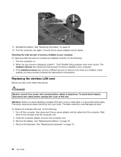
... amount of memory installed in your computer. 3. The Installed memory item shows the total amount of memory installed in this slot. To avoid shock hazard, disconnect the cables before opening the cover of memory from the computer. Connect the ac power adapter and all cables from what you installed, check whether you start , print these instructions. The ThinkPad Setup...
... amount of memory installed in your computer. 3. The Installed memory item shows the total amount of memory installed in this slot. To avoid shock hazard, disconnect the cables before opening the cover of memory from the computer. Connect the ac power adapter and all cables from what you installed, check whether you start , print these instructions. The ThinkPad Setup...


