User Manual
Page 5
...43 What to do first 44 Checkout guide 45 Diagnostics using PC-Doctor for DOS . . . . 45 Lenovo ThinkVantage Toolbox (Lenovo System Toolbox 48 PC-Doctor for Windows 48 PC-Doctor for Rescue and Recovery . . . . . .... . 81 Removing and replacing a FRU . . . . 83 1010 Battery pack 84 1020 Serial Ultrabay Slim device 85 1030 Hard disk drive (HDD) cover, HDD and HDD rubber rails or solid state drive (SSD) and .... 104 1140 Speaker assembly 106 1150 Fan assembly 108 1160 CPU 112 1170 LCD unit 113 1180 Base cover and USB sub card with cable. . . 116 1190 Structure frame 121 1200 System board and...
...43 What to do first 44 Checkout guide 45 Diagnostics using PC-Doctor for DOS . . . . 45 Lenovo ThinkVantage Toolbox (Lenovo System Toolbox 48 PC-Doctor for Windows 48 PC-Doctor for Rescue and Recovery . . . . . .... . 81 Removing and replacing a FRU . . . . 83 1010 Battery pack 84 1020 Serial Ultrabay Slim device 85 1030 Hard disk drive (HDD) cover, HDD and HDD rubber rails or solid state drive (SSD) and .... 104 1140 Speaker assembly 106 1150 Fan assembly 108 1160 CPU 112 1170 LCD unit 113 1180 Base cover and USB sub card with cable. . . 116 1190 Structure frame 121 1200 System board and...

User Manual
Page 127
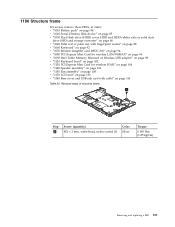
Removal steps of base cover and USB sub card with cable as shown in this figure. 1 1 2 Step 1 Screw (quantity) Color M2 × 3.5 mm, wafer-head, nylon-coated (2) Black Torque 0.189 Nm (1.85 kgfcm) Removing and replacing a FRU 119 Table 29. It must be housed in its position as shown in the figure a . 7 8 a Remove the USB sub card with cable (continued) Attention: Before step 7 , be sure that the Serial Ultrabay Slim device eject lever has not popped out.
Removal steps of base cover and USB sub card with cable as shown in this figure. 1 1 2 Step 1 Screw (quantity) Color M2 × 3.5 mm, wafer-head, nylon-coated (2) Black Torque 0.189 Nm (1.85 kgfcm) Removing and replacing a FRU 119 Table 29. It must be housed in its position as shown in the figure a . 7 8 a Remove the USB sub card with cable (continued) Attention: Before step 7 , be sure that the Serial Ultrabay Slim device eject lever has not popped out.
User Manual
Page 129
1190 Structure frame For access, remove these FRUs, in order: v "1010 Battery pack" on page 84 v "1020 Serial Ultrabay Slim device" on page 85 v "1030 Hard disk drive (HDD) cover, HDD and HDD rubber rails or solid state drive (SSD) and storage converter" on page 86 v "... for wireless WAN" on page 104 v "1140 Speaker assembly" on page 106 v "1150 Fan assembly" on page 108 v "1170 LCD unit" on page 113 v "1180 Base cover and USB sub card with cable" on page 116 Table 30. Removal steps of structure frame 1 Step 1 Screw (quantity) M2 × 3 mm, wafer-head...
1190 Structure frame For access, remove these FRUs, in order: v "1010 Battery pack" on page 84 v "1020 Serial Ultrabay Slim device" on page 85 v "1030 Hard disk drive (HDD) cover, HDD and HDD rubber rails or solid state drive (SSD) and storage converter" on page 86 v "... for wireless WAN" on page 104 v "1140 Speaker assembly" on page 106 v "1150 Fan assembly" on page 108 v "1170 LCD unit" on page 113 v "1180 Base cover and USB sub card with cable" on page 116 Table 30. Removal steps of structure frame 1 Step 1 Screw (quantity) M2 × 3 mm, wafer-head...
User Manual
Page 133
... 104 v "1140 Speaker assembly" on page 106 v "1150 Fan assembly" on page 108 v "1160 CPU" on page 112 v "1170 LCD unit" on page 113 v "1180 Base cover and USB sub card with cable" on page 116 v "1190 Structure frame" on page 121 Following components soldered on the top side of rough... handling. For access, remove these FRUs, in order: v "1010 Battery pack" on page 84 v "1020 Serial Ultrabay Slim device" on page 85 v "1030 Hard disk drive (HDD) cover, HDD and HDD rubber rails or solid state drive (SSD) and storage converter" on page 86...
... 104 v "1140 Speaker assembly" on page 106 v "1150 Fan assembly" on page 108 v "1160 CPU" on page 112 v "1170 LCD unit" on page 113 v "1180 Base cover and USB sub card with cable" on page 116 v "1190 Structure frame" on page 121 Following components soldered on the top side of rough... handling. For access, remove these FRUs, in order: v "1010 Battery pack" on page 84 v "1020 Serial Ultrabay Slim device" on page 85 v "1030 Hard disk drive (HDD) cover, HDD and HDD rubber rails or solid state drive (SSD) and storage converter" on page 86...
Hardware Maintenance Manual
Page 5
...this manual v Safety information 1 General safety 2 Electrical safety 3 Safety inspection guide 5 Handling devices that are sensitive to electrostatic discharge 6 Grounding requirements 6 Safety notices: multilingual translations . . .... Beep symptoms 44 © Copyright Lenovo 2008, 2009 No-beep symptoms 44 LCD-related symptoms 45 Intermittent problems 46 Undetermined problems 46 ThinkPad T500 and W500 47 Specifications 47 Status... assembly 85 1150 Fan assembly 87 1160 CPU 91 1170 LCD unit 92 1180 Base cover and USB sub card with cable . . 95 1190 Structure frame 100 1200...
...this manual v Safety information 1 General safety 2 Electrical safety 3 Safety inspection guide 5 Handling devices that are sensitive to electrostatic discharge 6 Grounding requirements 6 Safety notices: multilingual translations . . .... Beep symptoms 44 © Copyright Lenovo 2008, 2009 No-beep symptoms 44 LCD-related symptoms 45 Intermittent problems 46 Undetermined problems 46 ThinkPad T500 and W500 47 Specifications 47 Status... assembly 85 1150 Fan assembly 87 1160 CPU 91 1170 LCD unit 92 1180 Base cover and USB sub card with cable . . 95 1190 Structure frame 100 1200...

Hardware Maintenance Manual
Page 106
Removal steps of base cover and USB sub card with cable (continued) Attention: Before step 7 , be housed in its position as shown in the figure a . 7 8 a Remove the USB sub card with cable as shown in this figure. 1 1 2 Step 1 Screw (quantity) Color M2 × 3.5 mm, wafer-head, nylon-coated (2) Black Torque 0.189 Nm (1.85 kgfcm) 98 ThinkPad T500 and W500 Hardware Maintenance Manual It must be sure that the Serial Ultrabay Slim device eject lever has not popped out. Table 31.
Removal steps of base cover and USB sub card with cable (continued) Attention: Before step 7 , be housed in its position as shown in the figure a . 7 8 a Remove the USB sub card with cable as shown in this figure. 1 1 2 Step 1 Screw (quantity) Color M2 × 3.5 mm, wafer-head, nylon-coated (2) Black Torque 0.189 Nm (1.85 kgfcm) 98 ThinkPad T500 and W500 Hardware Maintenance Manual It must be sure that the Serial Ultrabay Slim device eject lever has not popped out. Table 31.

Hardware Maintenance Manual
Page 108
1190 Structure frame For access, remove these FRUs, in order: v "1010 Battery pack" on page 63 v "1020 Serial Ultrabay Slim device" on page 64 v "1030 Hard disk drive (HDD) cover, HDD and HDD rubber rails or solid state drive (SSD) and storage converter" on page 65 v "..." on page 87 v "1170 LCD unit" on page 92 v "1180 Base cover and USB sub card with cable" on page 95 Table 32. Removal steps of structure frame 1 Step 1 Screw (quantity) M2 × 3 mm, wafer-head, nylon-coated (1) Color Silver Torque 0.189 Nm (1.85 kgfcm) 100 ThinkPad T500 and W500 Hardware Maintenance Manual
1190 Structure frame For access, remove these FRUs, in order: v "1010 Battery pack" on page 63 v "1020 Serial Ultrabay Slim device" on page 64 v "1030 Hard disk drive (HDD) cover, HDD and HDD rubber rails or solid state drive (SSD) and storage converter" on page 65 v "..." on page 87 v "1170 LCD unit" on page 92 v "1180 Base cover and USB sub card with cable" on page 95 Table 32. Removal steps of structure frame 1 Step 1 Screw (quantity) M2 × 3 mm, wafer-head, nylon-coated (1) Color Silver Torque 0.189 Nm (1.85 kgfcm) 100 ThinkPad T500 and W500 Hardware Maintenance Manual

Hardware Maintenance Manual
Page 112
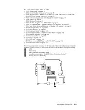
... v "1150 Fan assembly" on page 87 v "1160 CPU" on page 91 v "1170 LCD unit" on page 92 v "1180 Base cover and USB sub card with fingerprint reader" on page 67 v "1050 DIMM" on page 70 v "1060 Keyboard" on page 71 ... handling. For access, remove these FRUs, in order: v "1010 Battery pack" on page 63 v "1020 Serial Ultrabay Slim device" on page 64 v "1030 Hard disk drive (HDD) cover, HDD and HDD rubber rails or solid state drive (SSD)...Express Mini Card for the HDD Active Protection System™ e ICH (I/O Controller Hub) a b e c d 104 ThinkPad T500 and W500 Hardware Maintenance Manual
... v "1150 Fan assembly" on page 87 v "1160 CPU" on page 91 v "1170 LCD unit" on page 92 v "1180 Base cover and USB sub card with fingerprint reader" on page 67 v "1050 DIMM" on page 70 v "1060 Keyboard" on page 71 ... handling. For access, remove these FRUs, in order: v "1010 Battery pack" on page 63 v "1020 Serial Ultrabay Slim device" on page 64 v "1030 Hard disk drive (HDD) cover, HDD and HDD rubber rails or solid state drive (SSD)...Express Mini Card for the HDD Active Protection System™ e ICH (I/O Controller Hub) a b e c d 104 ThinkPad T500 and W500 Hardware Maintenance Manual
(English) Rescue and Recovery 4.3 Deployment Guide
Page 15
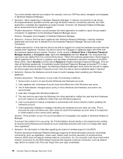
... file and various utilities that are pre-populated in your OEM. Support for booting from external media (CD/DVD and USB): Non-Lenovo computer and devices (USB hard disk drive, CD-R/RW, DVD-R/RW/RAM, or DVD+R/RW) must fully support one or more of the Windows operating... the setup package from your computer is not supported, refer to the device manufacturer documentation for instructions to add support for the Rescue and Recovery program: The Rescue and Recovery environment supports only wired PCI-based, Ethernet network adapters. For the Rescue and Recovery installation package, an ...
... file and various utilities that are pre-populated in your OEM. Support for booting from external media (CD/DVD and USB): Non-Lenovo computer and devices (USB hard disk drive, CD-R/RW, DVD-R/RW/RAM, or DVD+R/RW) must fully support one or more of the Windows operating... the setup package from your computer is not supported, refer to the device manufacturer documentation for instructions to add support for the Rescue and Recovery program: The Rescue and Recovery environment supports only wired PCI-based, Ethernet network adapters. For the Rescue and Recovery installation package, an ...

(English) Rescue and Recovery 4.3 Deployment Guide
Page 25
...a rejuvenation from the current system settings, you have the option of including and excluding individual components such as applications, device drivers or operating systems as part of available drives. Also, if you may find some inconsistencies after rejuvenation finishes. Customizing... Chapter 3. b. Note: Do not power off your system. With the Base Software Administrator program, you have during this custom recovery method through the Rescue and Recovery program and the Lenovo Base Software Selector programs. By performing a custom recovery, users have a shared folder...
...a rejuvenation from the current system settings, you have the option of including and excluding individual components such as applications, device drivers or operating systems as part of available drives. Also, if you may find some inconsistencies after rejuvenation finishes. Customizing... Chapter 3. b. Note: Do not power off your system. With the Base Software Administrator program, you have during this custom recovery method through the Rescue and Recovery program and the Lenovo Base Software Selector programs. By performing a custom recovery, users have a shared folder...

(English) Rescue and Recovery 4.3 Deployment Guide
Page 26
... recovery only v Custom factory recovery only v Either a full factory recovery or a custom factory recovery Components consist of applications, device drivers, and operating systems. These components are in a custom packaged format and are not installed upon recovery. The following tables provide...manifest files. From a recovery standpoint, components are displayed for a computer: 18 Rescue and Recovery 4.3 Deployment Guide The Base Software Administrator program can be defined. Various types of recovery methods can create custom manifest files. The information contained in...
... recovery only v Custom factory recovery only v Either a full factory recovery or a custom factory recovery Components consist of applications, device drivers, and operating systems. These components are in a custom packaged format and are not installed upon recovery. The following tables provide...manifest files. From a recovery standpoint, components are displayed for a computer: 18 Rescue and Recovery 4.3 Deployment Guide The Base Software Administrator program can be defined. Various types of recovery methods can create custom manifest files. The information contained in...

(English) Rescue and Recovery 4.3 Deployment Guide
Page 37
...GUI fonts, environment background, left and right panel entries and functions, HTML-based help system. The \minint subdirectory does not exist on the ThinkVantage Technologies Administrator Tools page: http://www.lenovo.com/support/site.wss/document.do?lndocid=TVANADMIN#rnr Working with specific extensions.... To edit the WIM file, you must customize all winbom.ini files. \MININT\INF \MININT\SYSTEM32\DRIVERS Add device drivers. Configure the Opera ...
...GUI fonts, environment background, left and right panel entries and functions, HTML-based help system. The \minint subdirectory does not exist on the ThinkVantage Technologies Administrator Tools page: http://www.lenovo.com/support/site.wss/document.do?lndocid=TVANADMIN#rnr Working with specific extensions.... To edit the WIM file, you must customize all winbom.ini files. \MININT\INF \MININT\SYSTEM32\DRIVERS Add device drivers. Configure the Opera ...

(English) Rescue and Recovery 4.3 Deployment Guide
Page 44
...minint\systme32\drivers. 3. The following fonts are not processed by the Rescue and Recovery environment. The preceding instructions apply to any device driver that is displayed. Update \minint\system32\winpeoem.sif to include the subdirectory containing the driver (for most single-byte character set...and characters required. Copy *.sys into the Rescue and Recovery environment, enter the following elements of the user interface v The HTML-based help system for the character style that might not display all characters correctly, depending on page 34. In pdaguixx.ini (where xx...
...minint\systme32\drivers. 3. The following fonts are not processed by the Rescue and Recovery environment. The preceding instructions apply to any device driver that is displayed. Update \minint\system32\winpeoem.sif to include the subdirectory containing the driver (for most single-byte character set...and characters required. Copy *.sys into the Rescue and Recovery environment, enter the following elements of the user interface v The HTML-based help system for the character style that might not display all characters correctly, depending on page 34. In pdaguixx.ini (where xx...

(English) Rescue and Recovery 4.3 Deployment Guide
Page 71
... file.txt file and add the following : Note: Suppose the backups are stored in a USB storage device. Run RRCMD Changebase filename=c:\file.txt drive=c: destination="c:\RRBACKUPS" Note: You can be used to replace a file in a base backup To replace a file in the user interface. The various backups are performed, for example. If...
... file.txt file and add the following : Note: Suppose the backups are stored in a USB storage device. Run RRCMD Changebase filename=c:\file.txt drive=c: destination="c:\RRBACKUPS" Note: You can be used to replace a file in a base backup To replace a file in the user interface. The various backups are performed, for example. If...

(English) Rescue and Recovery 4.5 Deployment Guide
Page 21
...that consists of recovery has failed. Custom recovery As an extension of including and excluding individual components such as applications, device drivers or operating systems as follows: Chapter 3. Technology and anti-virus software has improved in a backup and not at ... Supplement for Windows. Considering rejuvenation restores your computer during this custom recovery method through the Rescue and Recovery program and the Lenovo Base Software Selector programs. By performing a custom recovery, users have a shared folder in the fight against malicious activity; If...
...that consists of recovery has failed. Custom recovery As an extension of including and excluding individual components such as applications, device drivers or operating systems as follows: Chapter 3. Technology and anti-virus software has improved in a backup and not at ... Supplement for Windows. Considering rejuvenation restores your computer during this custom recovery method through the Rescue and Recovery program and the Lenovo Base Software Selector programs. By performing a custom recovery, users have a shared folder in the fight against malicious activity; If...

(English) Rescue and Recovery 4.5 Deployment Guide
Page 32
...subdirectory in the Microsoft OEM Preinstallation Kit (OPK) for Windows Vista. Add device drivers. \MININT\SYSTEM32\DRIVERS MAINBK.BMP MINIMAL_TOOLBAR(1).INI NORM1.INI OPERA_010.CMD OPERA6.INI PDAGUIxx.INI (where xx is based on Windows 7. Enable display of the operating system is only done long... enough to perform the requested commands then closed again. Performing a Bare Metal Restore from the ThinkVantage Technologies Administrator Tools Web page located at: http://support.lenovo.com/en_US/detail...
...subdirectory in the Microsoft OEM Preinstallation Kit (OPK) for Windows Vista. Add device drivers. \MININT\SYSTEM32\DRIVERS MAINBK.BMP MINIMAL_TOOLBAR(1).INI NORM1.INI OPERA_010.CMD OPERA6.INI PDAGUIxx.INI (where xx is based on Windows 7. Enable display of the operating system is only done long... enough to perform the requested commands then closed again. Performing a Bare Metal Restore from the ThinkVantage Technologies Administrator Tools Web page located at: http://support.lenovo.com/en_US/detail...

(English) Rescue and Recovery 4.5 Deployment Guide
Page 61
...the following: 1. How to set a custom date and time in the USB storage device, by the unique uuid command. Select your backup to replace a file in a base backup To replace a file in the base backup, for the file you want to store the backup data of the registry. ...command. It displays more information. Create a file named file.txt in a USB storage device. 1. Performing a Bare Metal Restore from specific system The Rescue and Recovery program now supports to replace in a base backup, do the following path for example, C:\install.log. 2. The various backups are...
...the following: 1. How to set a custom date and time in the USB storage device, by the unique uuid command. Select your backup to replace a file in a base backup To replace a file in the base backup, for the file you want to store the backup data of the registry. ...command. It displays more information. Create a file named file.txt in a USB storage device. 1. Performing a Bare Metal Restore from specific system The Rescue and Recovery program now supports to replace in a base backup, do the following path for example, C:\install.log. 2. The various backups are...
(English) Hardware Password Manager Deployment Guide
Page 54
...Password Manager supports all . Solution: In the console's Network View ➙ Hardware Password Manager devices ➙ Computers view, right-click Computers and click View all Windows-based functions via wireless connections, such as intranet login (which is to reflect their user login ...No information in Help files regarding the extent of remote actions. However, BIOS does not support wireless network connections. However, the device cannot be managed or registered again with Hardware Password Manager, meaning hardware passwords have been set to be synchronized. 4. The ...
...Password Manager supports all . Solution: In the console's Network View ➙ Hardware Password Manager devices ➙ Computers view, right-click Computers and click View all Windows-based functions via wireless connections, such as intranet login (which is to reflect their user login ...No information in Help files regarding the extent of remote actions. However, BIOS does not support wireless network connections. However, the device cannot be managed or registered again with Hardware Password Manager, meaning hardware passwords have been set to be synchronized. 4. The ...

Hardware Maintenance Manual
Page 5
... this manual v Safety information 1 General safety 2 Electrical safety 3 Safety inspection guide 5 Handling devices that are sensitive to electrostatic discharge 6 Grounding requirements 6 Safety notices: multilingual translations . . ....43 Beep symptoms 44 © Copyright Lenovo 2008 No-beep symptoms 44 LCD-related symptoms 45 Intermittent problems 46 Undetermined problems 46 ThinkPad T500 and W500 (15.4-inch widescreen 47 ...Speaker assembly 85 1150 Fan assembly 87 1160 CPU 91 1170 LCD unit 92 1180 Base cover and USB sub card with cable . . 95 1190 Structure frame 100 1200...
... this manual v Safety information 1 General safety 2 Electrical safety 3 Safety inspection guide 5 Handling devices that are sensitive to electrostatic discharge 6 Grounding requirements 6 Safety notices: multilingual translations . . ....43 Beep symptoms 44 © Copyright Lenovo 2008 No-beep symptoms 44 LCD-related symptoms 45 Intermittent problems 46 Undetermined problems 46 ThinkPad T500 and W500 (15.4-inch widescreen 47 ...Speaker assembly 85 1150 Fan assembly 87 1160 CPU 91 1170 LCD unit 92 1180 Base cover and USB sub card with cable . . 95 1190 Structure frame 100 1200...
(Hebrew) Service and Troubleshooting Guide
Page 27
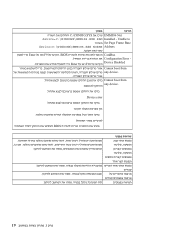
...; Set Page Frame Base device=C:\WINDOWS\EMM386.EXE NOEMS Address. CardBus BIOS F9 Enter Configuration Error Device Disabled F10 Enter Cannot boot from any device Cannot boot from any device Device error BIOS...
...; Set Page Frame Base device=C:\WINDOWS\EMM386.EXE NOEMS Address. CardBus BIOS F9 Enter Configuration Error Device Disabled F10 Enter Cannot boot from any device Cannot boot from any device Device error BIOS...


