User Manual
Page 5
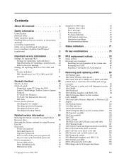
...CMV, and GAV products 41 General checkout 43 What to do first 44 Checkout guide 45 Diagnostics using PC-Doctor for DOS . . . . 45 Lenovo ThinkVantage Toolbox (Lenovo System Toolbox 48 PC-Doctor for Windows 48 PC-Doctor for Rescue and Recovery . . . . . 49 FRU tests 50 Power system checkout 52 ... Retaining the UUID 80 Reading or writing the ECA information . . . 81 Removing and replacing a FRU . . . . 83 1010 Battery pack 84 1020 Serial Ultrabay Slim device 85 1030 Hard disk drive (HDD) cover, HDD and HDD rubber rails or solid state drive (SSD) and storage converter 86 1040 Palm...
...CMV, and GAV products 41 General checkout 43 What to do first 44 Checkout guide 45 Diagnostics using PC-Doctor for DOS . . . . 45 Lenovo ThinkVantage Toolbox (Lenovo System Toolbox 48 PC-Doctor for Windows 48 PC-Doctor for Rescue and Recovery . . . . . 49 FRU tests 50 Power system checkout 52 ... Retaining the UUID 80 Reading or writing the ECA information . . . 81 Removing and replacing a FRU . . . . 83 1010 Battery pack 84 1020 Serial Ultrabay Slim device 85 1030 Hard disk drive (HDD) cover, HDD and HDD rubber rails or solid state drive (SSD) and storage converter 86 1040 Palm...

User Manual
Page 58
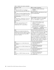
...Disks Diskette drive You can also diagnose the hard disk drive without starting up correctly. 2. Interactive Tests --> Diskette 50 ThinkPad T500 and W500 Hardware Maintenance Manual PC Card slot ExpressCard slot Diagnostics --> Systemboard --> PCMCIA 1. Interactive Tests --> Keyboard Hard... diskette from the BIOS Setup Utility, do as follows: 1. Power Diagnostics --> ThinkPad Devices --> AC Adapter, Battery 1 (Battery2) LCD unit 1. Run Diagnostics --> ThinkPad Devices --> ExpressCard slot. Using cursor keys, select Main hard disk drive or Ultrabay hard disk drive. 6.
...Disks Diskette drive You can also diagnose the hard disk drive without starting up correctly. 2. Interactive Tests --> Diskette 50 ThinkPad T500 and W500 Hardware Maintenance Manual PC Card slot ExpressCard slot Diagnostics --> Systemboard --> PCMCIA 1. Interactive Tests --> Keyboard Hard... diskette from the BIOS Setup Utility, do as follows: 1. Power Diagnostics --> ThinkPad Devices --> AC Adapter, Battery 1 (Battery2) LCD unit 1. Run Diagnostics --> ThinkPad Devices --> ExpressCard slot. Using cursor keys, select Main hard disk drive or Ultrabay hard disk drive. 6.

User Manual
Page 73
... is using a non-IBM or non-Lenovo hard disk drive (HDD), or an old generation IBM HDD which is plugged in Slot-1. System board. 2110 1. System board. 2112 Read error on a horizontal surface. Place the ThinkPad Notebook on HDD1 (Ultrabay hard disk drive) 1. Initialization error on... page 91. 2000 Hard Drive Active Protection sensor diagnostics failed.Press to continue.Press to the customer: If in the primary bay the customer is using a supported IBM/Lenovo HDD with the risk...
... is using a non-IBM or non-Lenovo hard disk drive (HDD), or an old generation IBM HDD which is plugged in Slot-1. System board. 2110 1. System board. 2112 Read error on a horizontal surface. Place the ThinkPad Notebook on HDD1 (Ultrabay hard disk drive) 1. Initialization error on... page 91. 2000 Hard Drive Active Protection sensor diagnostics failed.Press to continue.Press to the customer: If in the primary bay the customer is using a supported IBM/Lenovo HDD with the risk...

User Manual
Page 80
.... 7 Power on Green: The computer is charged between 0% to 5% of the capacity. Orange: The battery is on . Blinking green: Data is not in the Serial Ultrabay Slim device. When this indicator is on and is being transmitted. Blinking green: The battery is charged between 5% to 80% of the capacity. 9 AC power... the drive in sleep (standby) mode. 8 Battery status Green: The battery is enabled. This indicator stays lit whenever the computer is resuming normal operation. 72 ThinkPad T500 and W500 Hardware Maintenance Manual
.... 7 Power on Green: The computer is charged between 0% to 5% of the capacity. Orange: The battery is on . Blinking green: Data is not in the Serial Ultrabay Slim device. When this indicator is on and is being transmitted. Blinking green: The battery is charged between 5% to 80% of the capacity. 9 AC power... the drive in sleep (standby) mode. 8 Battery status Green: The battery is enabled. This indicator stays lit whenever the computer is resuming normal operation. 72 ThinkPad T500 and W500 Hardware Maintenance Manual
User Manual
Page 81
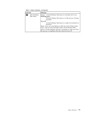
Table 7. Note: If you are using Windows 2000, the Serial Ultrabay Slim status indicator does not blink while a Serial Ultrabay Slim device is being detached. then the indicator turns off : A Serial Ultrabay Slim device is installed and in the process of being detached. Turn off . Blinking green: A Serial Ultrabay Slim device is completed; Status indicators (continued) Indicator 11 Serial Ultrabay Slim status Meaning Green: A Serial Ultrabay Slim device is ready to be attached or detached. Status indicators 73 Instead, a message box pops up when the process is in use.
Table 7. Note: If you are using Windows 2000, the Serial Ultrabay Slim status indicator does not blink while a Serial Ultrabay Slim device is being detached. then the indicator turns off : A Serial Ultrabay Slim device is installed and in the process of being detached. Turn off . Blinking green: A Serial Ultrabay Slim device is completed; Status indicators (continued) Indicator 11 Serial Ultrabay Slim status Meaning Green: A Serial Ultrabay Slim device is ready to be attached or detached. Status indicators 73 Instead, a message box pops up when the process is in use.
User Manual
Page 93
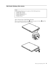
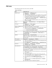
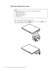
In step 2 , pull the lever a little to release the device from the bay. 1 2 3 Removing and replacing a FRU 85 1020 Serial Ultrabay Slim device Note: Serial Ultrabay Slim does not accept any of Serial Ultrabay Slim device When you release the switch in step 1 , the lever pops out. Removal steps of the following devices: v Ultrabay Plus™ devices v Ultrabay 2000™ devices v Ultrabay Enhanced devices v Ultrabay Slim devices v Ultrabay devices Table 10.
In step 2 , pull the lever a little to release the device from the bay. 1 2 3 Removing and replacing a FRU 85 1020 Serial Ultrabay Slim device Note: Serial Ultrabay Slim does not accept any of Serial Ultrabay Slim device When you release the switch in step 1 , the lever pops out. Removal steps of the following devices: v Ultrabay Plus™ devices v Ultrabay 2000™ devices v Ultrabay Enhanced devices v Ultrabay Slim devices v Ultrabay devices Table 10.

User Manual
Page 127
Removal steps of base cover and USB sub card with cable as shown in this figure. 1 1 2 Step 1 Screw (quantity) Color M2 × 3.5 mm, wafer-head, nylon-coated (2) Black Torque 0.189 Nm (1.85 kgfcm) Removing and replacing a FRU 119 Table 29. It must be housed in its position as shown in the figure a . 7 8 a Remove the USB sub card with cable (continued) Attention: Before step 7 , be sure that the Serial Ultrabay Slim device eject lever has not popped out.
Removal steps of base cover and USB sub card with cable as shown in this figure. 1 1 2 Step 1 Screw (quantity) Color M2 × 3.5 mm, wafer-head, nylon-coated (2) Black Torque 0.189 Nm (1.85 kgfcm) Removing and replacing a FRU 119 Table 29. It must be housed in its position as shown in the figure a . 7 8 a Remove the USB sub card with cable (continued) Attention: Before step 7 , be sure that the Serial Ultrabay Slim device eject lever has not popped out.
User Manual
Page 129
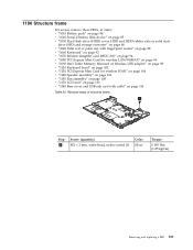
... (1.85 kgfcm) Removing and replacing a FRU 121 1190 Structure frame For access, remove these FRUs, in order: v "1010 Battery pack" on page 84 v "1020 Serial Ultrabay Slim device" on page 85 v "1030 Hard disk drive (HDD) cover, HDD and HDD rubber rails or solid state drive (SSD) and storage converter" on...
... (1.85 kgfcm) Removing and replacing a FRU 121 1190 Structure frame For access, remove these FRUs, in order: v "1010 Battery pack" on page 84 v "1020 Serial Ultrabay Slim device" on page 85 v "1030 Hard disk drive (HDD) cover, HDD and HDD rubber rails or solid state drive (SSD) and storage converter" on...
User Manual
Page 133
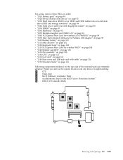
... System™ e ICH (I/O Controller Hub) a b e c d Removing and replacing a FRU 125 For access, remove these FRUs, in order: v "1010 Battery pack" on page 84 v "1020 Serial Ultrabay Slim device" on page 85 v "1030 Hard disk drive (HDD) cover, HDD and HDD rubber rails or solid state drive (SSD) and storage converter" on...
... System™ e ICH (I/O Controller Hub) a b e c d Removing and replacing a FRU 125 For access, remove these FRUs, in order: v "1010 Battery pack" on page 84 v "1020 Serial Ultrabay Slim device" on page 85 v "1030 Hard disk drive (HDD) cover, HDD and HDD rubber rails or solid state drive (SSD) and storage converter" on...
User Manual
Page 149
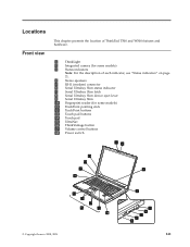
... chapter presents the location of ThinkPad T500 and W500 features and hardware. 1 ThinkLight 2 Integrated camera (for some models) 3 Status indicators Note: For the description of each indicator, see "Status indicators" on page 71. 4 Stereo speakers 5 RJ-11 (modem) connector 6 Serial Ultrabay Slim status indicator 7 Serial Ultrabay Slim latch 8 Serial Ultrabay Slim device eject lever 9 Serial...
... chapter presents the location of ThinkPad T500 and W500 features and hardware. 1 ThinkLight 2 Integrated camera (for some models) 3 Status indicators Note: For the description of each indicator, see "Status indicators" on page 71. 4 Stereo speakers 5 RJ-11 (modem) connector 6 Serial Ultrabay Slim status indicator 7 Serial Ultrabay Slim latch 8 Serial Ultrabay Slim device eject lever 9 Serial...

User Manual
Page 270
... extrapolation. Users of others. 262 ThinkPad T500 and W500 Hardware Maintenance Manual Trademarks vary significantly. The following terms are trademarks of Lenovo in the United States, other countries or both: Active Protection System Lenovo® Rescue and Recovery® ThinkLight® ThinkPad® ThinkVantage® TrackPoint® Ultrabay Ultrabay 2000 Ultrabay Enhanced Ultrabay Plus UltraNav® The following terms...
... extrapolation. Users of others. 262 ThinkPad T500 and W500 Hardware Maintenance Manual Trademarks vary significantly. The following terms are trademarks of Lenovo in the United States, other countries or both: Active Protection System Lenovo® Rescue and Recovery® ThinkLight® ThinkPad® ThinkVantage® TrackPoint® Ultrabay Ultrabay 2000 Ultrabay Enhanced Ultrabay Plus UltraNav® The following terms...
Hardware Maintenance Manual
Page 5
... 39 Numeric error codes 39 Error messages 43 Beep symptoms 44 © Copyright Lenovo 2008, 2009 No-beep symptoms 44 LCD-related symptoms 45 Intermittent problems 46 Undetermined problems 46 ThinkPad T500 and W500 47 Specifications 47 Status indicators 50 FRU tests 53 Fn key combinations... 55 FRU replacement notices 58 Screw notices 58 Retaining serial numbers 59 Removing and replacing a FRU 62 1010 Battery pack 63 1020 Serial Ultrabay Slim device 64...
... 39 Numeric error codes 39 Error messages 43 Beep symptoms 44 © Copyright Lenovo 2008, 2009 No-beep symptoms 44 LCD-related symptoms 45 Intermittent problems 46 Undetermined problems 46 ThinkPad T500 and W500 47 Specifications 47 Status indicators 50 FRU tests 53 Fn key combinations... 55 FRU replacement notices 58 Screw notices 58 Retaining serial numbers 59 Removing and replacing a FRU 62 1010 Battery pack 63 1020 Serial Ultrabay Slim device 64...
Hardware Maintenance Manual
Page 50
... hard disk drive) 2. If in the primary drive bay the customer is using a non-IBM or non-Lenovo hard disk drive (HDD), or an old generation IBM HDD which is using a supported IBM/Lenovo HDD with the risk in Slot-1. Reseat the hard disk drive. Read error on page 70. 2000 Hard... system. The latest version is attached to the computer. 3. Reseat the hard disk drive. 2. System board. 2102 1. Initialization error on HDD0 (Main hard disk drive) 1. Ultrabay™ hard disk drive. System board. 42 ThinkPad T500 and W500 Hardware Maintenance Manual
... hard disk drive) 2. If in the primary drive bay the customer is using a non-IBM or non-Lenovo hard disk drive (HDD), or an old generation IBM HDD which is using a supported IBM/Lenovo HDD with the risk in Slot-1. Reseat the hard disk drive. Read error on page 70. 2000 Hard... system. The latest version is attached to the computer. 3. Reseat the hard disk drive. 2. System board. 2102 1. Initialization error on HDD0 (Main hard disk drive) 1. Ultrabay™ hard disk drive. System board. 42 ThinkPad T500 and W500 Hardware Maintenance Manual

Hardware Maintenance Manual
Page 56
Table 7. Solid state drive v 64 GB, 8 mm high, SATA interface v 80 GB, 8 mm high, SATA interface v 128 GB, 8 mm high, SATA interface Serial Ultrabay Slim device (standard) v DVD ROM drive, 9.5 mm high v DVD/CD-RW combo drive, 9.5 mm high v DVD multi drive, 9.5 mm high v Blu-ray drive, 9.5 mm high ... (PC3-8500) card × 2 v 4-GB DDR3-1067 SDRAM SO-DIMM (PC3-8500) card × 1 Extended memory device v Intel Turbo Memory 2-GB Minicard (some models) 48 ThinkPad T500 and W500 Hardware Maintenance Manual
Table 7. Solid state drive v 64 GB, 8 mm high, SATA interface v 80 GB, 8 mm high, SATA interface v 128 GB, 8 mm high, SATA interface Serial Ultrabay Slim device (standard) v DVD ROM drive, 9.5 mm high v DVD/CD-RW combo drive, 9.5 mm high v DVD multi drive, 9.5 mm high v Blu-ray drive, 9.5 mm high ... (PC3-8500) card × 2 v 4-GB DDR3-1067 SDRAM SO-DIMM (PC3-8500) card × 1 Extended memory device v Intel Turbo Memory 2-GB Minicard (some models) 48 ThinkPad T500 and W500 Hardware Maintenance Manual

Hardware Maintenance Manual
Page 57
...) 2.6 Ah v Ultrabay Slim Li Polymer battery (3 cells) (option) AC adapter v 65-watt type v 90-watt type Preinstalled operating system v Windows XP Professional v Windows Vista® Home Basic (32 bit) v Windows Vista Home Premium (32 bit) v Windows Vista Business (32 bit) v Windows Vista Business (64 bit) v Windows Vista Ultimate (32 bit) ThinkPad T500 and...
...) 2.6 Ah v Ultrabay Slim Li Polymer battery (3 cells) (option) AC adapter v 65-watt type v 90-watt type Preinstalled operating system v Windows XP Professional v Windows Vista® Home Basic (32 bit) v Windows Vista Home Premium (32 bit) v Windows Vista Business (32 bit) v Windows Vista Business (64 bit) v Windows Vista Ultimate (32 bit) ThinkPad T500 and...

Hardware Maintenance Manual
Page 59
... written to 5% of the capacity. Sudden physical shock could cause drive errors. 7 Power on and ready to 20% of the capacity, and being charged. ThinkPad T500 and W500 51 Status indicators Indicator 1 Wireless status 2 Wireless PAN status R Meaning Green: The wireless feature (802.11 standard or 802.11n) is on... . Note: Do not move the system while the green drive-in the Serial Ultrabay Slim device. Orange: The battery is on , and the radio link is ready for use light is charged between 5% to use . Green: Bluetooth...
... written to 5% of the capacity. Sudden physical shock could cause drive errors. 7 Power on and ready to 20% of the capacity, and being charged. ThinkPad T500 and W500 51 Status indicators Indicator 1 Wireless status 2 Wireless PAN status R Meaning Green: The wireless feature (802.11 standard or 802.11n) is on... . Note: Do not move the system while the green drive-in the Serial Ultrabay Slim device. Orange: The battery is on , and the radio link is ready for use light is charged between 5% to use . Green: Bluetooth...

Hardware Maintenance Manual
Page 60
... when the process is being detached. Note: If you are using Windows 2000, the Serial Ultrabay Slim status indicator does not blink while a Serial Ultrabay Slim device is completed; Blinking green: A Serial Ultrabay Slim device is in use. Table 8. Turn off . 52 ThinkPad T500 and W500 Hardware Maintenance Manual Status indicators (continued) Indicator 11 Serial...
... when the process is being detached. Note: If you are using Windows 2000, the Serial Ultrabay Slim status indicator does not blink while a Serial Ultrabay Slim device is completed; Blinking green: A Serial Ultrabay Slim device is in use. Table 8. Turn off . 52 ThinkPad T500 and W500 Hardware Maintenance Manual Status indicators (continued) Indicator 11 Serial...
Hardware Maintenance Manual
Page 61
... without starting up correctly. 2. Using cursor keys, select Main hard disk drive or Ultrabay hard disk drive. 6. ThinkPad T500 and W500 53 Conexant Smart Modem Interrupt b. Then, run Diagnostics --> ThinkPad Devices --> HDD Active Protection Test. PC Card slot Diagnostics --> Systemboard --> PCMCIA ExpressCard...Systemboard --> Keyboard 2. Press Enter to the computer while the test is running. Table 9. If the ThinkPad Advanced Dock, the ThinkPad Advanced Mini Dock or the ThinkPad Essential Port Replicator is displayed at the lower left of the screen, press F1 to Compatibility, and run...
... without starting up correctly. 2. Using cursor keys, select Main hard disk drive or Ultrabay hard disk drive. 6. ThinkPad T500 and W500 53 Conexant Smart Modem Interrupt b. Then, run Diagnostics --> ThinkPad Devices --> HDD Active Protection Test. PC Card slot Diagnostics --> Systemboard --> PCMCIA ExpressCard...Systemboard --> Keyboard 2. Press Enter to the computer while the test is running. Table 9. If the ThinkPad Advanced Dock, the ThinkPad Advanced Mini Dock or the ThinkPad Essential Port Replicator is displayed at the lower left of the screen, press F1 to Compatibility, and run...
Hardware Maintenance Manual
Page 72
Removal steps of the following devices: v Ultrabay Plus™ devices v Ultrabay 2000™ devices v Ultrabay Enhanced devices v Ultrabay Slim devices v Ultrabay devices Table 12. 1020 Serial Ultrabay Slim device Note: Serial Ultrabay Slim does not accept any of Serial Ultrabay Slim device When you release the switch in step 1 , the lever pops out. In step 2 , pull the lever a little to release the device from the bay. 1 2 3 64 ThinkPad T500 and W500 Hardware Maintenance Manual
Removal steps of the following devices: v Ultrabay Plus™ devices v Ultrabay 2000™ devices v Ultrabay Enhanced devices v Ultrabay Slim devices v Ultrabay devices Table 12. 1020 Serial Ultrabay Slim device Note: Serial Ultrabay Slim does not accept any of Serial Ultrabay Slim device When you release the switch in step 1 , the lever pops out. In step 2 , pull the lever a little to release the device from the bay. 1 2 3 64 ThinkPad T500 and W500 Hardware Maintenance Manual

Hardware Maintenance Manual
Page 106
It must be sure that the Serial Ultrabay Slim device eject lever has not popped out. Table 31. Removal steps of base cover and USB sub card with cable as shown in the figure a . 7 8 a Remove the USB sub card with cable (continued) Attention: Before step 7 , be housed in its position as shown in this figure. 1 1 2 Step 1 Screw (quantity) Color M2 × 3.5 mm, wafer-head, nylon-coated (2) Black Torque 0.189 Nm (1.85 kgfcm) 98 ThinkPad T500 and W500 Hardware Maintenance Manual
It must be sure that the Serial Ultrabay Slim device eject lever has not popped out. Table 31. Removal steps of base cover and USB sub card with cable as shown in the figure a . 7 8 a Remove the USB sub card with cable (continued) Attention: Before step 7 , be housed in its position as shown in this figure. 1 1 2 Step 1 Screw (quantity) Color M2 × 3.5 mm, wafer-head, nylon-coated (2) Black Torque 0.189 Nm (1.85 kgfcm) 98 ThinkPad T500 and W500 Hardware Maintenance Manual